Using a Scene Graph
A scene graph is a dynamic data structure, similar to a multiway tree. Each node represents an object in a 3D world or perhaps an instruction to the renderer. Every node can have zero or more children nodes. The scene graph is traversed every frame to draw the visible world. The code you'll see that describes the scene graph classes can be installed into one CPP and H file, and added to the SceneGraph project. We'll take a look at the scene graph classes in detail and then I'll show you how to change your SceneGraph.cpp and SceneGraph.h files to install your new toys.
//////////////////////////////////////////////////// // // File: SceneNodes.h // // Contains some basic definitions for a simple // scene graph for use with DirectX 9. // //////////////////////////////////////////////////// #pragma once #include <list> #include <d3d9.h> #include <d3dx9math.h> #include "assert.h" #include "SmartPtr.h" #include "dxutil.h" #include "d3dutil.h" // Forward declarations class SceneNode; class Scene; class MovementController; typedef std::list<SmartPtr<SceneNode> > SceneNodeList; //////////////////////////////////////////////////// // // SceneNode Definition // //////////////////////////////////////////////////// class SceneNode { public: SceneNodeList m_children; virtual ~SceneNode(); virtual HRESULT VRenderChildren(Scene *); virtual HRESULT VRestore(Scene *); virtual HRESULT VUpdate(Scene *, DWORD const elapsedMs); virtual HRESULT VPreRender(Scene *) { return S_OK; } virtual HRESULT VRender(Scene *) { return S_OK; } virtual HRESULT VPostRender(Scene *) { return S_OK; } virtual void VSetTransform( const D3DXMATRIX *toWorld, const D3DXMATRIX *fromWorld=NULL) { } }; You can probably tell immediately that SceneNode is meant to be a base class. A bunch of trivial virtual functions is a clear give-away. The goal for this class design is to give some flexibility to programmers that create new objects that inherit from SceneNode. Here's the implementation of the non-trivial SceneNode methods:
//////////////////////////////////////////////////// // SceneNode Implementation //////////////////////////////////////////////////// SceneNode::~SceneNode() { // Get rid of all those pesky kids... while (!m_children.empty()) { m_children.pop_front(); } } HRESULT SceneNode::VRestore(Scene *pScene) { // This is meant to be called from any class // that inherits from SceneNode and overloads // VRestore() SceneNodeList::iterator i = m_children.begin(); while (i != m_children.end()) { (*i)->VRestore(pScene); i++; } return S_OK; } HRESULT SceneNode::VUpdate(Scene *pScene, DWORD const elapsedMs) { // This is meant to be called from any class // that inherits from SceneNode and overloads // VUpdate() SceneNodeList::iterator i = m_children.begin(); while (i != m_children.end()) { (*i)->VUpdate(pScene, elapsedMs); i++; } return S_OK; } HRESULT SceneNode::VRenderChildren(Scene *pScene) { // Iterate through the children.... SceneNodeList::iterator i = m_children.begin(); while (i != m_children.end()) { if ((*i)->VPreRender(pScene)==S_OK) { // You could short-circuit rendering // if an object returns E_FAIL from // VPreRender() (*i)->VRender(pScene); (*i)->VRenderChildren(pScene); } (*i)->VPostRender(pScene); i++; } return S_OK; } The two methods, VRestore() and VUpdate(), simply traverse their children nodes and recursively call the same methods. When you inherit from SceneNode and create a new object, don't forget to call the base class's SceneNode::VRestore() or SceneNode::VUpdate() if you happen to overload them. If you fail to do this, your children nodes won't get these calls. VRestore() is meant to recreate any programmatically created data after it has been lost. This is a similar concept to the section on lost 2D DirectDraw surfaces.
VUpdate() is meant to handle game logic, animations, or anything else that is meant to be decoupled from the rendering traversal. That's why it is called with the elapsed time, measured in milliseconds. You can use the elapsed time to make sure animations or other movements happen at a consistent speed, regardless of computer processing power. A faster CPU should always create a smoother animation, not necessarily a faster one!
The VRenderChildren() iterates through the child nodes and calls virtual functions you are meant to overload in inherited classes. VPreRender() is meant to perform any task that must occur before the render, such as a visibility test. VRender() does exactly what it advertises: It renders the object. A recursive call to VRenderChildren() is made to tranverse the scene graph, performing all these actions for every node. VPostRender() is meant to perform a post-rendering action, such as restoring a render state to it's original value.
| Gotcha | Don't even think of trying to attach a node to itself, or any of its descendants. Infinite recursion is not how I like to spend my off-time. |
Here's the definition of the Scene, a container for SceneNodes of all shapes and sizes.
//////////////////////////////////////////////////// // // Scene Definition (declared in SceneNodes.h) // // A heirarchical container of scene nodes. //////////////////////////////////////////////////// class Scene { public: IDirect3DDevice9 *m_pDevice; SmartPtr<SceneNode> m_root; ID3DXMatrixStack *m_matrixStack; SmartPtr<MovementController> m_pMovementController; Scene(IDirect3DDevice9 *device, SmartPtr<SceneNode> root); ~Scene(); HRESULT Render(); HRESULT Restore(); HRESULT Update(); }; The Scene knows about four kinds of data. The IDirect3DDevice9 is the interface to the DirectX rendering device, and is used throughout the SceneNodes. As you might expect, the scene also has a root node, the exact nature of which we'll get to in a moment.
The interesting bit that you might not have seen before is a Direct3D matrix stack. Back in the easy 3D chapter, we did plenty of work with matrix concatenation. Any number of matrices could be multiplied, or concatenated, to create any bizarre and twisted set of rotation and translation operations. In the case of a hierarchical model, like a human figure, these matrix concatenations can get tedious unless you can push them onto and pop them from a stack. Hang tight; examples are coming soon.
The last data item is a user interface object called a movement controller, which grabs input from the keyboard and mouse and can be used to move any object in the scene graph in arbitrary ways. In practice this controller affects the camera object, but there's nothing wrong with hooking it up to anything else. Here's the implementation of the Scene class:
//////////////////////////////////////////////////// // Scene Implementation (declared in SceneNodes.cpp) //////////////////////////////////////////////////// Scene::Scene(IDirect3DDevice9 *device, SmartPtr<SceneNode> root) : m_root(root) ,m_pMovementController(NULL) { m_pDevice = device; m_pDevice->AddRef(); D3DXCreateMatrixStack(0, &m_matrixStack); } Scene::~Scene() { SAFE_RELEASE(m_pDevice); SAFE_RELEASE(m_matrixStack); } HRESULT Scene::Render() { if (!m_root) return S_OK; // The scene root could be anything, but it // is usually a TransformNode with the identity // matrix if (m_root->VPreRender(this)==S_OK) { m_root->VRender(this); m_root->VRenderChildren(this); m_root->VPostRender(this); } return S_OK; } HRESULT Scene::Restore() { if (!m_root) return S_OK; return m_root->VRestore(this); } HRESULT Scene::Update() { static DWORD lastTime = 0; DWORD elapsedTime = 0; DWORD now = timeGetTime(); if (!m_root) return S_OK; if (lastTime == 0) { lastTime = now; } elapsedTime = now - lastTime; lastTime = now; // There's one controller. But that isn't // very usefull, is it??? You should make a list // of them. if (m_pMovementController) m_pMovementController->Update(elapsedTime); return m_root->VUpdate(this, elapsedTime); } The scene is created with a valid IDirect3DDevice9 interface and a root node. The movement controller doesn't have to exist at all until we want one, which we'll do when we actually create the scene later in the chapter.. The other calls to Scene::Update(), Scene::Render(), and Scene::Restore() kick start the hierarchical traversal of the entire scene graph starting at the root node. The call to Scene::Update() includes a call to the Win32 API timeGetTime(), a reasonably efficient timer, accurate to a few milliseconds.
Scene Graph Nodes
These data structures by themselves do absolutely nothing exciting. We need some classes that inherit from SceneNode to construct an interesting scene. We'll start with TransformNode, an object that encapsulates a frame of reference, or a transformation matrix. Any object in the scene will use the functionality of the TransformNode to position and orient itself in world space. You could even attach groups of objects as children of this node to move and orient them as a group, such as objects on a boat. If you add TransformNodes as children of existing TransformNode structures, you'll get an object hierarchy such as a human figure. It's a fundamental part of any scene graph. Here's the definition of the class:
//////////////////////////////////////////////////// // // TransformNode Definition // // This node changes the local object to world // transform by using D3D's Matrix Stack // //////////////////////////////////////////////////// class TransformNode : public SceneNode { public: D3DXMATRIX m_toWorld, m_fromWorld; TransformNode(const D3DXMATRIX *to, const D3DXMATRIX *from=NULL) { VSetTransform(to, from); } virtual HRESULT VPreRender(Scene *); virtual HRESULT VPostRender(Scene *); virtual void VSetTransform( const D3DXMATRIX *toWorld, const D3DXMATRIX *fromWorld=NULL); }; Did you notice that there are two matrices in this data structure? You already know that you need a matrix that transforms vertices from object space to world space, if you want to draw the object at any arbitrary location and orientation. It turns out to be incredibly useful to have an inverse of this matrix as well so that you can transform a vector that exists in world space back to object space. This is critical for making things like movement controllers, since they apply rotations and translations in object space. We'll see more about that later. Here's the code that implements TransformNode:
//////////////////////////////////////////////////// // TransformNode Implementation //////////////////////////////////////////////////// HRESULT TransformNode::VPreRender(Scene *pScene) { // Note this code carefully!!!!! It is COMPLETELY different // from some DirectX 9 documentation out there.... pScene->m_matrixStack->Push(); pScene->m_matrixStack->MultMatrixLocal(&m_toWorld); pScene->m_pDevice->SetTransform(D3DTS_WORLD, pScene->m_matrixStack->GetTop()); return S_OK; } HRESULT TransformNode::VPostRender(Scene *pScene) { pScene->m_matrixStack->Pop(); pScene->m_pDevice->SetTransform(D3DTS_WORLD, pScene->m_matrixStack->GetTop()); return S_OK; }; void TransformNode::VSetTransform(const D3DXMATRIX *toWorld, const D3DXMATRIX *fromWorld) { m_toWorld = *toWorld; if (!fromWorld) { // Good god this is expensive...why bother???? D3DXMatrixInverse(&m_fromWorld, NULL, &m_toWorld); } else { m_fromWorld = *fromWorld; } } Remember matrix concatenation? This class encapsulates matrix concatenation, and does it with a stack. The call to VPreRender() pushes a new matrix on the matrix stack. The next call is a little confusing, and I won't ask you to visualize it because when I tried I got a pounding headache—but here's the gist of it. The matrix that exists at the top of the stack is either the identity matrix or the result of all the concatenated matrices from the hierarchy in your parent nodes in the scene graph. As you traverse to child nodes deeper in the scene graph, they will push their own transform matrix on the stack and cause it to be concatenated with every transform up the chain, but by only doing one matrix multiplication. As you can see, this is quite efficient, and extremely flexible for implementing hierarchical objects.
You can imagine this by thinking about your hand as a self-contained hierarchical object. The root would be your palm, and attached to it are five children—the first segment of each of your five fingers. Each of those finger segments has one child, the segment without a fingernail. Finally, the segment with the fingernail attaches, making the palm its great-grandfather. If the transform matrix for one of those finger segments is rotated around the right axis, the finger should bend, carrying all the child segments with it. If I change the translation or rotation of the palm, the root object, everything moves. That is the basic notion of a hierarchical animation system.
| A Tale from the Pixel Mines | It's common for artists to create human figures with the hips, or should I say, groin as the root node. It's convenient because it is close to the center of the human body, and has three children: the torso and the two legs. One fine day the Ultima VIII team went to the park for lunch, and played a little Ultimate Frisbee. As happens frequently in that game, two players went to catch the Frisbee at the same time, and collided. One of them was curled up on the ground writhing in pain, and when I asked what happened I was told that they caught an elbow right in the root of their hierarchy. |
The call to VSetTransform() will calculate the inverse transform matrix for you if you didn't send it in. Yes it's somewhat expensive, if you've ever seen the formula for calculating the determinant of a 4x4 matrix you know what I'm talking about. If you've never seen it, just imagine an entire case of alphabet soup laid out on a recursive grid. It's gross.
But the inverse transform can be very useful, especially if you want to set a view matrix. If a camera were an object in a 3D world with a regular transform of its own, the view matrix that you would use to transform everything in the world to camera space is the inverse of the camera object's regular transform matrix. It can also be extremely useful for object picking, where you transform a screen space coordinate into world space, and finally into object space to find out what part of an object your mouse pointer is touching.
Another important scene graph node encapsulates the location and orientation of the camera. Here's the definition and implementation for the CameraNode:
//////////////////////////////////////////////////// // CameraNode Definition // // A camera node controls the D3D view transform // //////////////////////////////////////////////////// class CameraNode : public TransformNode { public: CameraNode(const D3DXMATRIX *t) : TransformNode(t) { } virtual HRESULT VUpdate(Scene *, DWORD const elapsedMs); }; HRESULT CameraNode::VUpdate(Scene *pScene, DWORD const ) { pScene->m_pDevice->SetTransform( D3DTS_VIEW, &m_fromWorld ); return S_OK; } It inherits from TransformNode to take advantage of the matrix stack. If we wanted to, we could attach the camera node to any object in the scene, and as it moved around the camera would automatically follow. The call to VUpdate() sets the IDirect3DDevice9's view transformation. A good thing to note right off is that scene graphs are tough to optimize. A robust version of this simpleton scene graph technology would be to check for changes in the m_fromWorld transform and if nothing changed, to leave Direct3D alone—every call takes time.
| Best Practice | Avoid calling members of the IDirect3DDevice9 class unless you absolutely have to. Unnecessary calls to the renderer will slow it down. |
We still haven't seen anything that will actually draw a shape on the screen yet. Here's a class you'll recognize from earlier in the book-Grid:
//////////////////////////////////////////////////// // // Grid Definition // // A slightly modified version of Grid from // the beginning 3D chapter // //////////////////////////////////////////////////// class Grid : public TransformNode { protected: LPDIRECT3DTEXTURE9 m_pTexture; // the grid texture LPDIRECT3DVERTEXBUFFER9 m_pVerts; // the grid verts LPDIRECT3DINDEXBUFFER9 m_pIndices; // the grid index DWORD m_numVerts; DWORD m_numPolys; DWORD m_gridSize; DWORD m_color; const TCHAR * m_textureFile; public: Grid(const DWORD gridSize, const DWORD color, const TCHAR *textureFile, const D3DXMATRIX *t); ~Grid(); HRESULT VRestore(Scene *pScene); HRESULT VRender(Scene *pScene); }; //////////////////////////////////////////////////// // Grid Implementation //////////////////////////////////////////////////// Grid::Grid(const DWORD gridSize, const DWORD color, const TCHAR *textureFile, const D3DXMATRIX *t) : TransformNode(t) { m_gridSize = gridSize; m_color = color; m_textureFile = textureFile; m_pTexture = NULL; m_pVerts = NULL; m_pIndices = NULL; m_numVerts = m_numPolys = 0; } Grid::~Grid() { SAFE_RELEASE(m_pTexture); SAFE_RELEASE(m_pVerts); SAFE_RELEASE(m_pIndices); } HRESULT Grid::VRestore(Scene *pScene) { // The code is exactly the same as in the Grid class // you've seen - go grab the code you saw previously. . . } HRESULT Grid::VRender(Scene *pScene) { // This is slightly different from the Chapter 7 implementation... // We take a little care to restore render states after we change them... LPDIRECT3DDEVICE9 pDevice = pScene->m_pDevice; DWORD oldLightMode; pDevice->GetRenderState( D3DRS_LIGHTING, &oldLightMode ); pDevice->SetRenderState( D3DRS_LIGHTING, FALSE ); DWORD oldCullMode; pDevice->GetRenderState( D3DRS_CULLMODE, &oldCullMode ); pDevice->SetRenderState( D3DRS_CULLMODE, D3DCULL_NONE ); // Setup our texture. Using textures introduces the texture stage states, // which govern how textures get blended together (in the case of multiple // textures) and lighting information. In this case, we are modulating // (blending) our texture with the diffuse color of the vertices. pDevice->SetTexture( 0, m_pTexture ); pDevice->SetTextureStageState( 0, D3DTSS_COLOROP, D3DTOP_MODULATE ); pDevice->SetTextureStageState( 0, D3DTSS_COLORARG1, D3DTA_TEXTURE ); pDevice->SetTextureStageState( 0, D3DTSS_COLORARG2, D3DTA_DIFFUSE ); pDevice->SetStreamSource( 0, m_pVerts, 0, sizeof(COLORED_TEXTURED_VERTEX) ); pDevice->SetIndices(m_pIndices); pDevice->SetFVF( D3DFVF_COLORED_TEXTURED_VERTEX ); pDevice->DrawIndexedPrimitive( D3DPT_TRIANGLELIST,0,0,m_numVerts,0,m_numPolys ); // Notice that the render states are returned to // their original settings..... // Could there be a better way??? pDevice->SetTexture (0, NULL); pDevice->SetRenderState( D3DRS_LIGHTING, oldLightMode ); pDevice->SetRenderState( D3DRS_CULLMODE, oldCullMode ); return S_OK; } The implementation of the Grid class is exactly the same as you remember from the first 3D chapter, with two exceptions. First, the names of the methods to have been changed to conform with the SceneNode base class. Second, the render method restores the render state after the geometry is sent to the card with DrawIndexedPrimitive.
This is one of the quirky things about a scene graph architecture: You can't be sure what the render state is at the beginning of a call to VRender(), so you tend to set the render states you absolutely need to render your object, and you restore settings after you're done with the render. If you think this will result in calling SetRenderState way too many times, you are absolutely right. You could encapsulate render states in an object of some kind, and create a utility function that figures out which render states need setting and which are good the way they are. Even better, this fictional RenderStateDelta object could be pre-calculated when nodes get added or removed from the scene graph, since they probably don't change much at run time. In any case, you should take the problem of minimizing the calls to renderer seriously.
A 3D game would be pretty boring with nothing but grids drawing at various positions and rotations. If you want interesting shapes you'll need to create them in a modeling tool like 3D Studio Max. Modeling tools are precise tools for creating shapes for your game levels or dynamic objects. DirectX can't read a ".MAX" or ".3DS" file directly, you'll need to convert it to a ".X" file with DirectX's conv3ds.exe utility. You can find help for this program in MSDN and elsewhere on the web.
Once you have a ".X" file, you can create a mesh object that DirectX can read natively, and all you need is a way to plug this object into the scene graph. The node you are looking for is MeshNode:
//////////////////////////////////////////////////// // // MeshNode Definition // // Attaches a D3D mesh object to the scene graph // with an accompanying material // //////////////////////////////////////////////////// class MeshNode : public TransformNode { protected: ID3DXMesh *m_mesh; D3DMATERIAL9 m_material; public: MeshNode(ID3DXMesh *mesh, const D3DXMATRIX *t, const D3DMATERIAL9 &material) : TransformNode(t) { m_mesh = mesh; m_material = material; m_mesh->AddRef(); } virtual ~MeshNode() { SAFE_RELEASE(m_mesh); } virtual HRESULT VRender(Scene *); }; HRESULT MeshNode::VRender(Scene *pScene) { pScene->m_pDevice->SetMaterial( &m_material ); return m_mesh->DrawSubset(0); } This node encapsulates ID3DXMesh, a D3D object that is created from a loaded ".X" file, DirectX's mesh file format. You can create simple meshes with the DirectX Mesh Viewer Utility, such as boxes, spheres, and all the teapots you could ever want. MeshNode inherits from TransferNode to utilize its position and orientation features, and adds D3DMATERIAL9 so that the mesh objects can render with different color and light properties.
Building Your Scene
With only the classes you've seen you can build a pretty complicated set of objects in a 3D world. I'll show you the code necessary to build the scene shown in Figure 10.1.
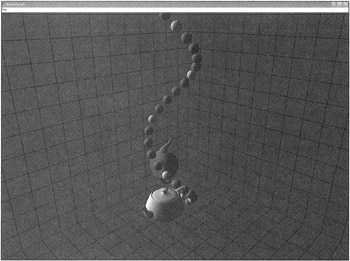
Figure 10.1: A Basic Scene— Teapots, Little Balls, and Some Grids.
Something that isn't visible in the figure is that the balls are hierarchically linked with the lowest ball at the root. If this ball is moved or rotated the entire spiral structure would move with it. Any member of this structure could be rotated or translated without affecting any parent nodes—only the children. Here's the code to build this scene:
//////////////////////////////////////////////////// // Free Function to Build the Scene //////////////////////////////////////////////////// Scene *BuildScene(IDirect3DDevice9 *d3dDevice) { // Setup some materials - we'll use these for // making the same mesh appear in multiple // colors D3DMATERIAL9 colors[5]; D3DUtil_InitMaterial( colors[0]. 1.0f, 1.0f, 1.0f ); // white D3DUtil_InitMaterial( colors[l], 0.0f, 1.0f, 1.0f ); // cyan D3DUtil_InitMaterial( colors[2], 1.0f, 0.0f, 0.0f ); // red D3DUtil_InitMaterial( colors[3], 0.0f, 1.0f, 0.0f ); // green D3DUtil_InitMaterial( colors[4], 0.0f, 0.0f, 1.0f ); // blue // The identity matrix is always useful D3DXMATRIX ident; D3DXMatrixIdentity(&ident); // We'll use these rotations for some teapots and grid objects D3DXMATRIX rotateX, rotateZ; D3DXMatrixRotationZ(&rotateZ, D3DX_PI / 2.0f); D3DXMatrixRotationX(&rotateX, -D3DX_PI / 2.0f); // Create the root, and the camera. // Remeber how to use smart pointers?? I hope so! SmartPtr<SceneNode> root(new TransformNode(&ident)); SmartPtr<SceneNode> camera(new CameraNode(&ident)); root->m_children.push_back(camera); ID3DXMesh *teapot; if( SUCCEEDED( D3DXCreateTeapot( d3dDevice, &teapot, NULL ) ) ) { // Teapot #1 - a white one at (x=6,y=2,z=4) D3DXMATRIX trans; D3DXMatrixTranslation(&trans,6,2,4); SmartPtr<SceneNode> mesh1(new MeshNode(teapot, &trans, colors[0])); root->m_children.push_back(mesh1); // Teapot #2 - a cyan one at (x=3,y=2,z=1) // with a D3DXMatrixTranslation(&trans, 3,2,1); D3DXMATRIX result; D3DXMatrixMultiply(&result, &rotateZ, &trans); SmartPtr<SceneNode> mesh2(new MeshNode(teapot, &result, colors[1])); root->m_children.push_back(mesh2); // We can release the teapot now, meshl and mesh2 AddRef'd it. SAFE_RELEASE(teapot); } ID3DXMesh *sphere; if ( SUCCEEDED( D3DXCreateSphere( d3dDevice, .25, 16, 16, &sphere, NULL) ) ) { // We're going to create a spiral of spheres... // starting at (x=3, y=0, z=3), and spiraling // upward about a local Y axis. D3DXMATRIX trans; D3DXMatrixTranslation(&trans, 3,0,3); SmartPtr<SceneNode> sphere1(new MeshNode(sphere, &trans, colors[4]) ); root->m_children.push_back(sphere1); // Here's the local rotation and translation. // We'll rotate about Y, and then translate // up (along Y) and forward (along Z). D3DXMATRIX rotateY; D3DXMatrixRotationY(&rotateY, D3DX_PI / 8.0f); D3DXMATRIX trans2; D3DXMatrixTranslation(&trans2, 0, 0.5, 0.5); D3DXMATRIX result; D3DXMatrixMultiply(&result, &trans2, &rotateY); for (int i=0; i<25; i++) { // If you didn't think smart pointers were cool - // watch this! No leaked memory.... // Notice this is a heirarchy.... SmartPtr<SceneNode> sphere2( new MeshNode(sphere, &result, colors[i%5]) ); spherel->m_children.push_back(sphere2); sphere1 = sphere2; } // We can release the sphere now, all the cylinders AddRef'd it. SAFE_RELEASE(sphere); } // Here are the grids...they make it easy for us to // see where the coordinates are in 3D space. SmartPtr<SceneNode> grid1( new Grid(40, 0x00400000, "Textures\\grid.dds", &ident)); root->m_children.push_back(grid1); SmartPtr<SceneNode> grid2( new Grid(40, 0x00004000, "Textures\\grid.dds", &rotateX)); root->m_children.push_back(grid2); SmartPtr<SceneNode> grid3( new Grid(40, 0x00000040, "Textures\\grid.dds", &rotateZ)); root->m_children.push_back(grid3); // Everything has been attached to the root. Now // we attach the root to the scene. Scene *scene = new Scene(d3dDevice, root); scene->Restore(); // A movement controller is going to control the camera, // but it could be constructed with any of the objects you see in this // function. You can have your very own remote controlled sphere. // What fun... SmartPtr<MovementController> m_pMovementController( new MovementController(camera)); scene->m_pMovementController = m_pMovementController; return scene; } This code makes good use of the SmartPtr class you read about in Chapter 3. If we had to call a na ve reference counting mechanism explicitly this code would be a lot longer, and a lot less clearer.
The root node of the scene graph is a simple TransformNode with the identity as its transform matrix. Everything in the scene graph is attached to this node, including the camera node, which will be used to set the view transform matrix if the camera moves about the scene. After the camera is added to the scene, a teapot is created using the D3DXCreateTeapot call. Why would DirectX bother to have a special call to create a teapot? A little research on the web will find the answer:
| A Tale from the Pixel Mines | "Aside from that, people have pointed out that it is a useful object to test with. It's instantly recognizable, it has complex topology, it self-shadows, there are hidden surface issues, it has both convex and concave surfaces, as well as 'saddle points.' It doesn't take much storage space—it's rumored that some of the early pioneers of computer graphics could type in the teapot from memory." - quoted directly from http://sjbaker.org/teapot/. |
Some 3D graphics professionals have even given this shape a special name—the "teapotahedron." It turns out that the original teapot that has come to be the official symbol of SIGGRAPH now lies in the Ephemera Collection of the Computer History Museum in Mountain View, California. Someday I should make a pilgrimage.
The code creates one teapot mesh, and attaches it to two MeshNode objects. This is perfectly fine and good, since the ID3DXMesh object is a COM based doo-dad and can therefore be reference counted.
The sphere objects are created next, but with a twist. I can't believe I wrote that! Once you're done rolling your eyes you'll see that I'm not kidding. The goal of the sphere creation is to make a complicated hierarchical object. If we animated the sphere's orientation randomly, the entire spiral structure would wag around like my dog's tail gone haywire.
The first sphere is attached to the root node just like the teapots. Then the code enters a loop, which creates a new sphere and attaches it to the first sphere. The last line of the loop does an odd thing. If you think it looks like a tail pointer in a linked list you aren't far from being wrong at all. Remember that sphere1 and sphere2 are essentially pointers to spheres. They don't seem like pointers because they are being managed by the SmartPtr template class, which does all the reference counting for you. As the loop iterates, new spheres are created and added to the deepening hierarchy.
Take a moment to look at the definition of the transform matrix, result. It rotates its target about the Y-axis by π/8 radians, then moves it up a half unit and forward a half unit. Stare at this transform a moment and you'll see that a deepening hierarchy of objects using this transform will resemble a single helix shape.
The grid objects are created next, and they are positioned to sit on the axis planes. Each grid object is attached directly to the root node. On another inspection it might have been wise to attach three grids to another TransformNode, and attach that node to the root. If I had done it that way I could have moved the grid objects as a single entity.
Once everything has been created and attached to the root node, the root node itself is attached to the scene, and the scene Restore() function is called to traverse each node and call it's overloaded SceneNode::VRestore method. This call will kick start your scene into action. In our case, the only node that happens to use VRestore is the Grid object, but there's nothing that would keep you from creating other nodes that did useful work outside of their constructors.
There's one important class I've failed to mention, the MovementController used in our scene to move the camera in and around the scene with a familiar interface from our many hours getting fragged in Quake.
A Useful Camera Controller
A camera controller needs to grab some keyboard and mouse input and translate that input into camera movement that people expect. The camera movement I'm speaking of performs the following tasks:
-
Moves the camera straight ahead when the player presses 'W,' and straight backwards when the user presses 'S.'
-
When the left mouse button is held, mouse movement will yaw and pitch the camera.
-
The camera has total freedom of movement and can fly about the scene wherever we wish.
This controller class uses two interface classes from the user interface chapter:
//////////////////////////////////////////////////// // // IKeyboardSensitive & IMouseSensitive // Interface Definition // //////////////////////////////////////////////////// class IKeyboardSensitive { virtual void OnKeyDown(const BYTE c)=0; virtual void OnKeyUp(const BYTE c)=0; }; class IMouseSensitive { public: virtual void OnMouseMove(const POINTS &mousePos) = 0; virtual void OnLButtonDown(const POINTS &mousePos) = 0; virtual void OnLButtonUp(const POINTS &mousePos) = 0; virtual void OnRButtonDown(const POINTS &mousePos) = 0; virtual void OnRButtonUp(const POINTS &mousePos) = 0; }; //////////////////////////////////////////////////// // // MovementController Definition // // Implements a quake-style movement controller // //////////////////////////////////////////////////// class MovementController : public IMouseSensitive, public IKeyboardSensitive { protected: D3DXMATRIX m_matFromWorld; D3DXMATRIX m_matToWorld; D3DXMATRIX m_matPosition; BOOL m_bLeftMouseDown; POINTS m_mousePos; // The current mouse postion POINTS m_mousePosOnDown; // The position of the mouse on // a down event BYTE m_bKey[256]; // Which keys are up and down // Orientation Controls FLOAT m_fTargetYaw; FLOAT m_fTargetPitch; FLOAT m_fYaw; FLOAT m_fPitch; FLOAT m_fPitchOnDown; FLOAT m_fYawOnDown; SmartPtr<SceneNode> m_object; public: MovementController(SmartPtr<SceneNode> object); void SetObject(SmartPtr<SceneNode> newObject); void Update(DWORD const elapsedMs); public: void OnMouseMove(const POINTS &mousePos); void OnLButtonDown(const POINTS &mousePos); void OnLButtonUp(const POINTS &mousePos); void OnRButtonDown(const POINTS &mousePos) { } void OnRButtonUp(const POINTS &mousePos) { } void OnKeyDown(const BYTE c) { m_bKey[c] = true; } void OnKeyUp(const BYTE c) { m_bKey[c] = false; } const D3DXMATRIX *GetToWorld() { return &m_matToWorld; } const D3DXMATRIX *GetFromWorld() { return &m_matFromWorld; } }; Note that the class has three transform matrices. You'll recognize the to-world and from-world transforms from the TransformNode class, but it also keeps a position transform matrix separate from the others. The On Key Down() and On KeyUp() events simply record which buttons are being depressed in a Boolean matrix—nothing tough here.
Most of the member variables track the movement of the mouse and its effects. When the left mouse button goes down the current position is recorded and compared with movement events until the button is released. Horizontal movement of the mouse affects yaw of the object, and vertical movement affects pitch. The member variables that include pitch and yaw in their names are used to calculate the magnitude of the movement events, translated into rotations. Here's the implementation of the movement controller class:
//////////////////////////////////////////////////// // MovementController Implementation //////////////////////////////////////////////////// #define MAX(a, b) ((a) >= (b) ? (a) : (b)) #define MIN(a, b) ((a) < (b) ? (a) : (b)) MovementController::MovementController(SmartPtr<SceneNode> object) : m_object(object) { D3DXMatrixIdentity(&m_matFromWorld); D3DXMatrixIdentity(&m_matToWorld); D3DXMatrixIdentity(&m_matPosition); m_fTargetYaw = m_fTargetPitch = 0.0f; m_fYaw = m_fPitch = 0.0f; m_bLeftMouseDown = false; memset(m_bKey, 0x00, sizeof(m_bKey)); } void MovementController::OnMouseMove(const POINTS &mousePos) { if (m_bLeftMouseDown) { // Every time the mouse moves, figure out how far and in // which direction. The X axis is for yaw, the Y axis is // for pitch. m_fTargetYaw = m_fYawOnDown + (m_mousePosOnDown.x - mousePos.x); m_fTargetPitch = m_fPitchOnDown + (mousePos.y - m_mousePosOnDown.y); } } void MovementController::OnLButtonDown(const POINTS &mousePos) { // The mouse is down - record where it happened. m_bLeftMouseDown = true; m_mousePosOnDown = mousePos; m_fYawOnDown = m_fTargetYaw; m_fPitchOnDown = m_fTargetPitch; } void MovementController::OnLButtonUp(const POINTS &) { m_bLeftMouseDown = false; } void MovementController::Update(DWORD const) { if (m_bKey['W'] || m_bKey['S']) { // In D3D, the "look at" default is always // the positive Z axis. D3DXVECTOR4 at = D3DXVECTOR4(0.0f,0.0f,1.0f ,0.0); if (m_bKey['S']) at *= -1; D3DXVECTOR4 atWorld(0,0,0,0); // This will give us the "look at" vector // in world space - we'll use that to move // the camera. D3DXVec4Transform(&atWorld, &at, &m_matToWorld); // But not an entire meter at a time! atWorld *= 0.1f; D3DXMATRIX camTranslate; D3DXMatrixTranslation(&camTranslate, atWorld.x, atWorld.y, atWorld.z): // The newly created delta position matrix, camTranslate, // is concatenated with the member position matrix. D3DXMatrixMultiply(&m_matPosition, &m_matPosition, &camTranslate); } if (m_bLeftMouseDown) { // The secret formula!!! Don't give it away! m_fYaw += (m_fTargetYaw - m_fYaw) * ( 0.35f ); m_fTargetPitch = MAX(-90, MIN(90, m_fTargetPitch)); m_fPitch += (m_fTargetPitch - m_fPitch) * ( 0.35f ); // Calculate the new rotation matrix from the camera // yaw and pitch. D3DXMATRIX matRot; D3DXMatrixRotationYawPitchRoll( &matRot, -m_fYaw * D3DX_PI / 180, // yaw m_fPitch * D3DX_PI / 180, // pitch 0); // roll // Create the new object-to-world matrix, and the // new world-to-object matrix. D3DXMatrixMultiply(&m_matToWorld, &matRot, &m_matPosition); D3DXMatrixInverse(&m_matFromWorld, NULL, &m_matToWorld); m_object->VSetTransform(&m_matToWorld, &m_matFromWorld); } } The first four methods: the constructor, OnMouseMove, OnLButtonDown, and OnLButtonUp are pretty self explanatory. The event based methods simply record what happened. The real meat of this function is inside Update(), which our scene graph will call whenever its Update() function is called. Update() has two independent sections. The first one handles object translation forward and backward along its "look-at" vector in world space. The second handles object rotations based on mouse movement.
If you want something to move forward, you must find out in which direction "forward" is. In DirectX, forward is always the positive Z-axis. Since you have a to-world transform, all you need to do is transform a unit Z vector into world space, and you'll be rewarded with a unit vector that points forward in the world for your object. Note that the unit vector is multiplied by -1 if we want to move backwards.
| Gotcha | This implies something very serious about how your artists create their 3D models. In DirectX, "up" is always the Y-axis and "forward" is always the Z-axis. You'll want to make sure your artists are creating models that follow this scheme. An artist might create a rocket model in the classic pose, standing straight up, ready for launch. This would be wrong. The artist should create it with its body skewered on the Z-axis. When you move it "forward," along its transformed Z in world space, it will do exactly as you expect. One more nit about model creation: Make sure that artists create models with convenient origins. Some artists might create a model of a door standing straight up, centered on the origin. This would also be wrong. The door should be able to rotate around its hinge without figuring out wacky interim translations so the artist should place a door hinge directly above the origin. When someone opens the door, all that will be needed in the game is a simple rotation about the Y-axis. This kind of thing is very unintuitive for artists, and also isn't encouraged by many modeling tools. Most tools like 3D Studio Max tend to model things centered on the origin, and not every object has a natural rotation about its center of mass—a door being the best example. |
Now we have a translation vector in world space, but it doesn't make sense to apply it directly to the object in question—it's not the right size. Usually you would calculate the maximum speed and acceleration of the object, and multiply the resulting world space vector with a scalar value to get something in the range you want. In this code, I'm simply limiting the vector to 1/10 of a unit. The resulting world space vector is used to construct a translation matrix, which is concatenated with the position matrix of the controller. Thus concludes the first part, and the easiest part, of this controller. Next come the rotations.
The first three lines of the rotation calculation are not that hard to visualize. Think of the yaw case, because it's easier and it doesn't have wacky limits. We arbitrarily limit the pitch to straight up and down. We'll break the yaw calculation down to an atomic level so you can see what's going on. When the left mouse button goes down, this code runs:
m_mousePosOnDown = mousePos; m_fYawOnDown = m_fTargetYaw;
The current mouse position is recorded as well as the current target yaw. When the mouse moves around as shown here:
m_fTargetYaw = m_fYawOnDown + (m_mousePosOnDown.x - mousePos.x);
The target yaw becomes the sum of the yaw recorded when the mouse went down, which is the same value the first time the mouse moves, and the delta mouse horizontal movement. The target yaw therefore becomes a new yaw based on the difference between where we started and how far the mouse has been moved.
Finally, the update:
m_fYaw += (m_fTargetYaw - m_fYaw) * ( 0.35f );
This formula figures out how far to rotate the camera, in degrees, based on the number of pixels the mouse has moved. There's a mysterious 0.35f multiplier in there. It alters the yaw calculation by a constant. The higher the constant, the farther your rotation will be for the same mouse movement. Notice that this constant cares nothing for screen width. Mouse movement is measured in pixels, but remember that the amount of physical movement it takes to move the mouse one pixel is pretty similar regardless of your current screen resolution.
The pitch calculation works in the same way, but it has an upper and lower limit. We don't want to deal with the camera pitching up and over—it would be upside down! The yaw and pitch are converted to radians and sent into a call that will create a transform matrix with yaw, pitch, and roll angles. Our roll angle is set to zero. The resulting matrix is concatenated with the to-world transformation matrix. An inverse matrix is calculated, and sent into the VSetTransform() of our controlled object. This implies that the movement controller can be used to control any object in the scene, which is completely true. Instead of attaching it to the camera node, I could have attached it to one of the sphere nodes, and watched them wiggle around as I activated the mouse.
Plugging the SceneGraph into the DirectX Playground
Here's exactly what you need to do to install your scene graph nodes into the SceneGraph.cpp and SceneGraph.h files that were automatically created with the DirectX 9 project wizard. First, go into the .h file and add the scene as a member of CMyD3DApplication:
class CMyD3DApplication : public CD3DApplication { // Leave the class exactly the same! // ADD THIS CODE! for the SceneGraph project... class Scene* m_pScene; }; The rest of the changes will be made to the .cpp file. First, add the #include for your scene node classes:
// ADD THIS CODE! for the SceneGraph project... #include "SceneNodes.h"
Second, set the scene member variable to NULL in the constructor for the application class:
CMyD3DApplication::CMyD3DApplication() { // ... this code stays exactly as it was created. // ADD THIS CODE! for the SceneGraph project... m_pScene = NULL; } Change InitDeviceObjects() to add a call to the free function that builds the scene:
HRESULT CMyD3DApplication::InitDeviceObjects() { // Init the font m_pFont->InitDeviceObjects( m_pd3dDevice ); // ADD THIS CODE! for the SceneGraph project... m_pScene = BuildScene(m_pd3dDevice); return S_OK; } FrameMove() becomes a lot simpler—you only have to call Scene::Update():
HRESULT CMyD3DApplication::FrameMove() { // CHANGE THIS CODE! for the SceneGraph project... m_pScene->Update(); return S_OK; } Render() has a similar change. This is where Scene::Render() is called:
HRESULT CMyD3DApplication::Render() { // Clear the viewport m_pd3dDevice->Clear( 0L, NULL, D3DCLEAR_TARGET|D3DCLEAR_ZBUFFER, 0x000000ff, 1.0f, 0L ); // Begin the scene if( SUCCEEDED( m_pd3dDevice->BeginScene() ) ) { // CHANGE THIS CODE! for the SceneGraph project... if (m_pScene) m_pScene->Render(); // Render stats and help text //RenderText(); // End the scene. m_pd3dDevice->EndScene(); } return S_OK; } MsgProc has some significant changes. The keyboard and mouse events are sent directly to the movement controller class:
LRESULT CMyD3DApplication::MsgProc( HWND hWnd, UINT msg, WPARAM wParam, LPARAM lParam ) { switch( msg ) { case WM_PAINT: { if( m_bLoadingApp ) { // Draw on the window tell the user that the app is loading // TODO: change as needed HDC hDC = GetDC( hWnd ); TCHAR strMsg[MAX_PATH]; wsprintf( strMsg, TEXT("Loading... Please wait") ); RECT rct; GetClientRect( hWnd, &rct ); DrawText( hDC, strMsg, -l, &rct, DT_CENTER|DT_VCENTER|DT_SINGLELINE ); ReleaseDC( hWnd, hDC ); } break; } // ADD THIS CODE! for the SceneGraph project... case WM_KEYDOWN: if (m_pScene && m_pScene->m_pMovementController) m_pScene->m_pMovementController-> OnKeyDown(static_cast<const BYTE>(wParam)); break; case WM_KEYUP: if (m_pScene && m_pScene->m_pMovementController) m_pScene->m_pMovementController-> OnKeyUp(static_cast<const BYTE>(wParam)); break; case WM_MOUSEMOVE: if (m_pScene && m_pScene->m_pMovementController) m_pScene->m_pMovementControl1er-> OnMouseMove(MAKEPOINTS(lParam)); break; case WM_LBUTTONDOWN: SetCapture(hWnd); if (m_pScene && m_pScene->m_pMovementController) m_pScene->m_pMovementController-> OnLButtonDown(MAKEPOINTS(lParam)); break; case WM_LBUTTONUP: SetCapture(NULL); if (m_pScene && m_pScene->m_pMovementController) m_pScene->m_pMovementController-> OnLButtonUp(MAKEPOINTS(lParam)); break; case WM_RBUTTONDOWN: SetCapture(hWnd); if (m_pScene && m_pScene->m_pMovementController) m_pScene->m_pMovementController-> OnRButtonDown(MAKEPOINTS(lParam)); break; case WM_RBUTTONUP: SetCapture(NULL); if (m_pScene && m_pScene->m_pMovementController) m_pScene->m_pMovementController-> OnRButtonUp(MAKEPOINTS(lParam)); break; } return CD3DApplication::MsgProc( hWnd, msg, wParam, lParam ); } Finally, don't forget to delete your scene when the application exits:
HRESULT CMyD3DApplication::DeleteDeviceObjects() { // TODO: Cleanup any objects created in InitDeviceObjects() m_pFont->DeleteDeviceObjects(); // ADD THIS CODE! for the SceneGraph project... SAFE_DELETE(m_pScene); return S_OK; } That is all you need to create a simple scene graph. It may seem like an extremely simplistic architecture but it's more flexible that you'd think. Each node you design can add functionality and special effects to all their children nodes. Here are some examples:
-
A billboard node: Sets the transform matrix of all the child nodes such that they always face the camera. Use this for trees or light glare.
-
A sky node: A huge box that sits over your scene and translates exactly in sync with the camera position. It creates the illusion that it exists at an extreme distance.
-
Level of detail node: A node that chooses one node in its child list for rendering based on the node's distance from the camera.
-
A material node: Sets the default material for all children nodes.
-
A world sector node: Defines a 3D volume that completely contains all of its children nodes. You use it to determine if any children need to draw based on camera direction, or interposed opaque world sectors.
-
A mirror node: Defines a portal through which the scene is rerendered from a different point of view, and stenciled onto a texture.
I'm sure you can come up with other cool stuff.