Creating a Database Schema
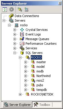
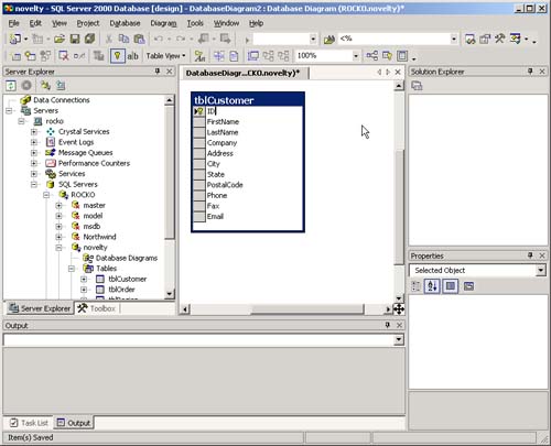
| Although creating a list of tables and fields is a good way to nail down the structure of the database, you may also want to be able to look at the tables and fields in a graphical format. That will let you see not only which tables and fields are available to you, but also how they relate to each other. You do so by creating a schema. A schema is a road map to your database. A schema comprises diagrams of all the tables, fields, and relationships in your database. Including a database schema as a part of your software design is important because it gives you a quick way to see what's going on in your database. Schemas also are important long after the database design process has been completed. You'll need the schema to perform multitable queries on the data. A good graphical schema answers questions such as: Which tables do I need to join to list all the orders greater than $50.00 that came in from customers in Minnesota in the last 24 hours? (For more information on how to create queries based on more than one table, see Chapter 2.) There is no one standard way to create database schemas, although there are many tools that you can use to create them. The drawing tool Visio is flexible, fast, and easy to use and it integrates well with other Windows applications, particularly Microsoft Office. Visio is now shipped as part of Visual Studio.NET Enterprise Architect edition; it's also available separately. You're not limited to using Visio when creating a graphical database schema. You can use what ever drawing tool you're comfortable with. Microsoft Windows Paint is a workable option, as are Microsoft Word's drawing features. Using Visual Studio to Create a DatabaseThere are a number of ways to create a database in SQL Server. It has its own set of tools, known as SQL Enterprise Manager, which enables you to create databases and tables graphically or programmatically (using SQL commands). Available are a number of external tools that enable you to work with database structures (one of which, Visio, is described later in this chapter). Visual Studio.NET has an outstanding facility for working with a SQL Server database. This facility is contained in Server Explorer, a new Visual Studio feature that lets you work with all kinds of server software in an integrated way. To use Server Explorer to create a SQL Server database do the following.
Expanding the outline view for the database that you just created reveals five categories of database objects available from VS.NET:
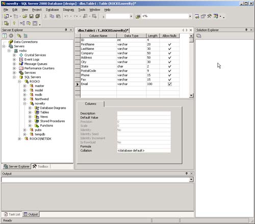
As you can't do much in a database without a table, first create one by doing the following.
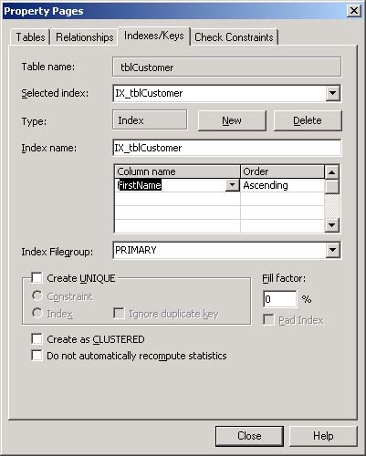
Designating Indexes and the Primary KeyNow that you've created the basic table, one thing remains to be done: You must designate indexes. An index is an attribute that you can assign to a field, making it easier for the database engine to retrieve data based on information stored in that field. For example, if you have a database that tracks employees, your application will probably tend to look up employees by last name, department, and individual ID number. It makes sense then to create indexes on each of these fields, to make the process of retrieving records based on these fields faster. Once you've realized the benefits of indexes in database design, you might ask yourself the question: If indexes make lookups faster, why not place an index on every field in every table? The answer is that there's a diminishing return with indexes. Indexes make your database physically larger, so if you have too many indexes, they will consume far too much memory and disk space, making your computer run more slowly. In addition a lot of maintenance is involved in updating indexes, which obviously nullifies the benefit of having an index in the first place. There's no hard and fast rule for how many indexes each table should have, but in general, you should create indexes for the fields that you envision will be queried most often. (For more information on how to use the information in a field as a query criterion to retrieve sets of records, see Chapter 2.) A primary key is a special type of index. A field that is designated as a table's primary key uniquely identifies the record. So, unlike other types of indexes, no two records in the same table may have the same value in its primary key field. Also, when you designate a field as a primary key, no record may contain an empty, or null, value in that field. When you designate a field in a table as that table's primary key, you can create relationships between that table and other tables in your database. Every table you create should at least have a primary key, and it should also be indexed on those fields you expect to be queried the most. In the case of tblCustomer, as with many database tables, the primary key will be the ID field. (You should have made this field the primary key earlier when you created tblCustomer.) The secondary indexes will be the LastName and FirstName fields. Now you can create two more indexes, for the FirstName and LastName fields, by doing the following.
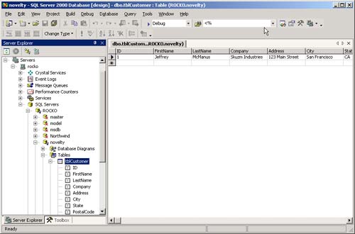
Now that you've created the data structure of the table, you may want to enter data into it. Server Explorer makes it easy; to work with data in the table, simply right-click on it in the Server Explorer window and choose Retrieve Data From Table from the pop-up menu. A data-entry grid appears, as shown in Figure 1.4 Figure 1.4. Entering data into a newly created table, using the Retrieve Data From Table feature of Server Explorer
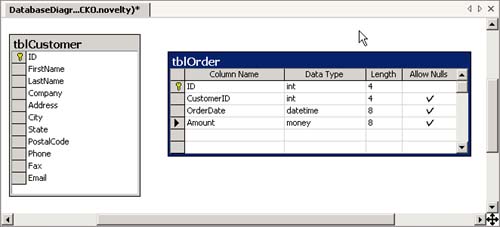
You can enter data into this grid by typing; when you move off a row the data you enter is automatically saved in the database. Don't bother entering data into the ID field. Remember, because you designated it as an identity column when you created the table, the database engine will fill in an ID for you automatically when the new record is created. Now that you've gone through the steps to create a single table in your database, you should be able to use Visual Studio.NET Server Explorer to model virtually any kind of database you require. However, at this stage there is one thing that can get in your way: the ability to model complicated relationships between multiple tables in a complex data design. You can use a database diagram to simplify that task. Creating Database DiagramsA database diagram is a visual representation of the tables in a database. You can use the diagramming features provided by SQL Server to create tables and the relationships between them visually. To create a database diagram in Visual Studio.NET's Server Explorer, do the following.
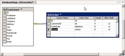
Now that you have tables for customers and orders, it makes sense to document the relationship that exists between them. Specifically, whenever an order is created, the ID of the customer will always be copied from the customer record's ID field to the CustomerID field of tblOrder. To reflect this action in the database diagram do the following.
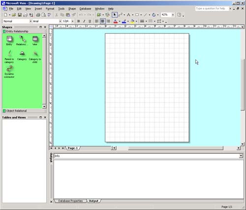
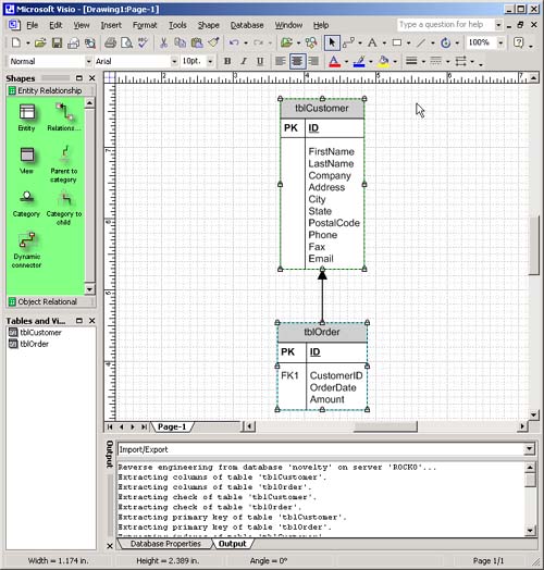
To finish your work here, choose File, Save DatabaseDiagram1 from the menu. In the Save Database Diagram dialog box, give the diagram the name Relationships. You should receive a warning dialog indicating that tables are about to be created in the database; answer Yes so that VS.NET can create tblOrder. It's particularly useful that SQL Server creates and stores the database diagram within the database itself. Thus you can always get to the diagram, even from different tools. (You can manipulate database diagrams in SQL Enterprise Manager, as well as in VS.NET.) Using Microsoft Visio to View and Alter a Database SchemaYou may find it useful to use a graphical tool other than VS.NET to create, inspect, and modify database schemas. The diagramming tool Microsoft Visio has the capability to diagram database structures automatically; it can also easily reverse engineer nearly any kind of existing database structure. This capability makes this tool particularly useful for documenting and working with the database schemas of databases that were designed in the mists of time by programmers unknown. Note It isn't strictly necessary for you to know how to use Visio to set up a SQL Server database. It's just a different way of rolling database design and documentation tasks into a single set of operations. If you feel comfortable using Visual Studio's Server Explorer (or SQL Server's own Enterprise Manager tools), or if you don't have access to the version of Visio that comes with Visual Studio Enterprise Architect, you can safely skip this section. Reverse engineering a database inspects an existing database schema and creates an entity relationship diagram (ERD) from it. An entity relationship diagram is a type of symbolic database design that focuses on the broad categories of data known as entities (typically stored in the database as tables). To reverse engineer a database schema using Visio, follow these steps.
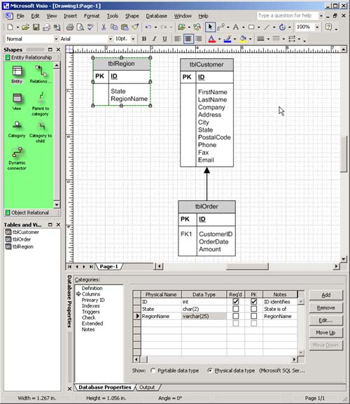
At this point you may be asking yourself, Why was that process so tedious and painful? The reason is that the Reverse Engineer Wizard kicked off a second wizard that created something called an ODBC data source. ODBC is an old Microsoft technology for providing interoperability between relational databases for application developers. (It's described in more depth in the VB6 edition of this book; it's not used extensively in VS.NET, so we're not repeating that discussion here.) The important thing to know about ODBC is that, once you've created a named ODBC data source using the steps in this section, you don't have to do it again. The next time you need to work with the Novelty database on your computer, you can simply use the ODBC data source that you just defined. You may now want to add another table to the database through Visio. Recall that Brad Jones's cocktail-napkin design for this database included the ability to divide customers into regions. Thus you'll need a table of regions, which you can add in Visio as follows.
When you're done, the graphic should look like Figure 1.10. Figure 1.10. The Visio ERD diagram containing the new definition for tblRegion
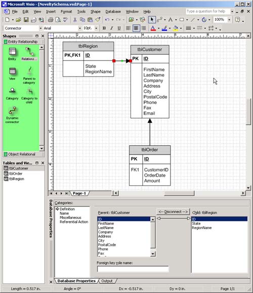
Note The preceding method is a very simple way to create a database schema; however, more involved methods might suit your purposes better. In fact, Visio has a number of specialized templates for creating database diagrams. There is a relationship between the new tblRegion and the existing tblCustomer (through the State fields that exist in both tables), which your diagram should reflect. You can create a relationship between two tables in Visio by using the Relationship shape, as follows.
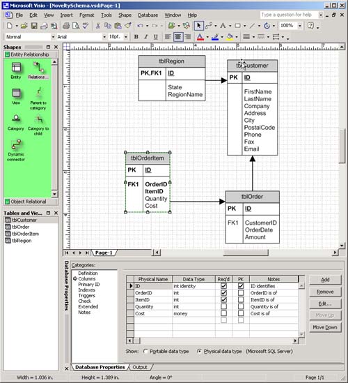
Now that you've drawn the diagram for a new table in your database, you can use Visio to create the table in the database. To do so, select the Visio menu command Database, Update. The Visio Database Update Wizard will launch, asking you how you want to perform the update. You may want Visio simply to generate a Data Definition Language (DDL) script that will perform the necessary changes to your database; this decision will also have the side benefit of documenting the changes in case you need to replicate them later. (For more information on how DDL commands work, see Chapter 2.) Or you may simply want Visio to make the changes to the database easily. You have the option to perform either or both operations with Visio's Update Database Wizard. Often, creating a graphical database schema will reveal flaws in your design. For example, the database design that you have so far enables the business to store information on customers and orders. But orders consist of items taken from the company's inventory and sold to the customer. With your current design, there's no way to see what the customer actually ordered. The solution to this problem is to create a new table for items associated with an order. The design of this new table looks like the following.
There is a one-to-many relationship, then, between the tblOrder table and the tblOrderItem table. The database schema now should look like that in Figure 1.12. Figure 1.12. The evolved database schema, including relationships among four tables in the database
The complete Visio file is included in the downloadable source code for this book from the Addison-Wesley Web site, www.awprofessional.com. Note Don't confuse the process of developing a database schema with a software design methodology. Most successful software development organizations have a design methodology in place that dictates what business problems the software is supposed to solve, how the software application will look, how it will be built, and the like. You should consider all these issues before you design a database. |
EAN: 2147483647
Pages: 97