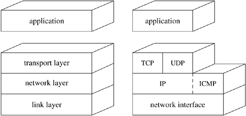
13.1. IPv4 Network Protocols IPv4 was developed under the sponsorship of DARPA, for use on the ARPANET [DARPA, 1983; McQuillan & Walden, 1977]. The protocols are commonly known as TCP/IP, although TCP and IP are only two of the many protocols in the family. These protocols do not assume a reliable subnetwork that ensures delivery of data. Instead, IPv4 was devised for a model in which hosts were connected to networks with varying characteristics and the networks were interconnected by routers. The Internet protocols were designed for packet-switching networks using datagrams sent over links such as Ethernet that provide no indication of delivery. This model leads to the use of at least two protocol layers. One layer operates end to end between two hosts involved in a conversation. It is based on a lower-level protocol that operates on a hop-by-hop basis, forwarding each message through intermediate routers to the destination host. In general, there exists at least one protocol layer above the other two: It is the application layer. The three layers correspond roughly to levels 3 (network), 4 (transport), and 7 (application) in the ISO Open Systems Interconnection reference model [ISO, 1984]. The protocols that support this model have the layering illustrated in Figure 13.1. The Internet Protocol (IP) is the lowest-level protocol in the Model; this level corresponds to the ISO network layer. IP operates hop-by-hop as a datagram is sent from the originating host to the destination via any intermediate routers. It provides the network-level services of host addressing, routing, and, if necessary, packet fragmentation and reassembly if intervening networks cannot send an entire packet in one piece. All the other protocols use the services of IP. The Transmission Control Protocol (TCP) and User Datagram Protocol (UDP) are transport-level protocols that provide additional facilities to applications that use IP. Each protocol adds a port identifier to IP's host address so that local and remote sockets can be identified. TCP provides connection-oriented, reliable, unduplicated, and flow-controlled transmission of data; it supports the stream socket type in the Internet domain. UDP provides a data checksum for checking integrity in addition to a port identifier, but otherwise adds little to the services provided by IP. UDP is the protocol used by datagram sockets in the Internet domain. The Internet Control Message Protocol (ICMP) is used for error reporting and for other, simple network-management tasks; it is logically a part of IP but, like the transport protocols, is layered above IP. It is usually not accessed by users. Raw access to the IP and ICMP protocols is possible through raw sockets (see Section 12.7 for information on this facility). Figure 13.1. IPv4 protocol layering. Key: TCP Transmission Control Protocol; UDP User Datagram Protocol; IP Internet Protocol; ICMP Internet Control Message Protocol. 
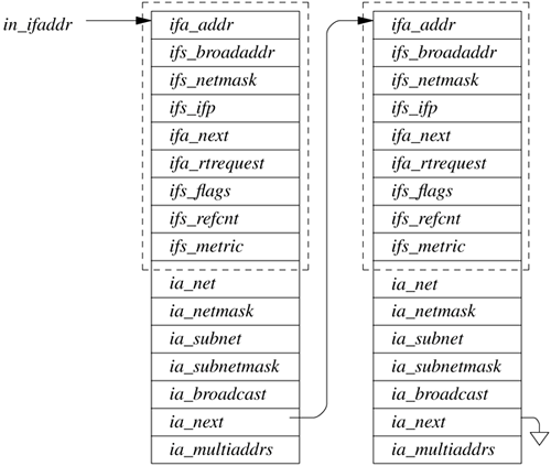
The Internet protocols were designed to support heterogeneous host systems and architectures that use a wide variety of internal data representations. Even the basic unit of data, the byte, was not the same on all host systems; one common type of host supported variable-sized bytes. The network protocols, however, require a standard representation. This representation is expressed using the octet an 8-bit byte. We shall use this term as it is used in the protocol specifications to describe network data, although we continue to use the term byte to refer to data or storage within the system. All fields in the Internet protocols that are larger than an octet are expressed in network byte order, with the most significant octet first. The FreeBSD network implementation uses a set of routines or macros to convert 16-bit and 32-bit integer fields between host and network byte order on hosts (such as PC systems) that have a different native ordering. IPv4 Addresses An IPv4 address is a 32-bit number that identifies the network on which a host resides as well as uniquely identifying a network interface on that host. It follows that a host with network interfaces attached to multiple networks has multiple addresses. Network addresses are assigned in blocks by Regional Internet Registries (RIRs) to Internet Service Providers (ISPs), which then dole out addresses to companies or individual users. If address assignment were not done in this centralized way, conflicting addresses could arise in the network, and it would be impossible to route packets correctly. Historically IPv4 addresses were rigidly divided into three classes (A, B, and C) to address the needs of large, medium, and small networks [Postel, 1981a]. Three classes proved to be too restrictive and also too wasteful of address space. The current IPv4 addressing scheme is called Classless Inter-Domain Routing (CIDR) [Fuller et al., 1993]. In the CIDR scheme each organization is given a contiguous group of addresses described by a single value and a netmask. For example, an ISP might have a group of addresses defined by an 18-bit netmask. This means that the network is defined by the first 18 bits, and the remaining 14 bits can potentially be used to identify hosts in the network. In practice, the number of hosts is less because the ISP will further break up this space into smaller networks, which will reduce the number of bits that can effectively be used. It is because of this scheme that routing entries store arbitrary netmasks with routes. Each Internet address assigned to a network interface is maintained in an in_ifaddr structure that contains a protocol-independent interface-address structure and additional information for use in the Internet domain (see Figure 13.2). When an interface's network mask is specified, it is recorded in the ia_subnetmask field of the address structure. The network mask, ia_netmask, is still calculated based on the type of the network number (class A, B, or C) when the interface's address is assigned, but this is no longer used to determine whether a destination is on or off the local subnet. The system interprets local Internet addresses using ia_subnetmask value. An address is considered to be local to the subnet if the field under the subnetwork mask matches the subnetwork field of an interface address. Figure 13.2. Internet interface address structure (in_jfaddr). 
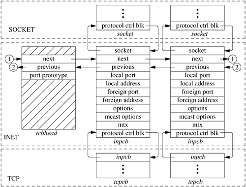
Broadcast Addresses On networks capable of supporting broadcast datagrams, 4.2BSD used the address with a host part of zero for broadcasts. After 4.2BSD was released, the Internet broadcast address was defined as the address with a host part of all is [Mogul, 1984]. This change and the introduction of subnets both complicated the recognition of broadcast addresses. Hosts may use a host part of 0s or 1s to signify broadcast, and some may understand the presence of subnets, whereas others may not. For these reasons, 4.3BSD and later BSD systems set the broadcast address for each interface to be the host value of all is but allow the alternate address to be set for backward compatibility. If the network is subnetted, the subnet field of the broadcast address contains the normal subnet number. The logical broadcast address for the network also is calculated when the address is set; this address would be the standard broadcast address if subnets were not in use. This address is needed by the IP input routine to filter input packets. On input, FreeBSD recognizes and accepts subnet and network broadcast addresses with host parts of 0s or 1s, as well as the address with 32 bits of 1 ("broadcast on this physical link"). Internet Multicast Many link-layer networks, such as Ethernet, provide a multicast capability that can address groups of hosts but is more selective than broadcast because it provides several different multicast group addresses. IP provides a similar facility at the network-protocol level, using link-layer multicast where available [Deering, 1989]. IP multicasts are sent using destination addresses with high-order bits set to 1110. Unlike host addresses, multicast addresses do not contain network and host portions; instead, the entire address names a group, such as a group of hosts using a particular service. These groups can be created dynamically, and the members of the group can change over time. IP multicast addresses map directly to physical multicast addresses on networks such as the Ethernet, using the low 24 bits of the IP address along with a constant 24-bit prefix to form a 48-bit link-layer address. For a socket to use multicast, it must join a multicast group using the setsockopt system call. This call informs the link layer that it should receive multicasts for the corresponding link-layer address, and it also sends a multicast membership report using the Internet Group Management Protocol (Cain et al., 2002) . Multicast agents on the network can thus keep track of the members of each group. Multicast agents receive all multicast packets from directly attached networks and forward multicast datagrams as needed to group members on other networks. This function is similar to the role of routers that forward normal (unicast) packets, but the criteria for packet forwarding are different, and a packet can be forwarded to multiple neighboring networks. Internet Ports and Associations At the IP level, packets are addressed to a host rather than to a process or communications port. However, each packet contains an 8-bit protocol number that identifies the next protocol that should receive the packet. Internet transport protocols use an additional identifier to designate the connection or communications port on the host. Most protocols (including TCP and UDP) use a 16-bit port number for this purpose. Each transport protocol maintains its own mapping of port numbers to processes or descriptors. Thus, an association, such as a connection, is fully specified by the tuple <source address, destination address, protocol number, source port, destination port>. Connection-oriented protocols, such as TCP, must enforce the uniqueness of associations; other protocols generally do so as well. When the local part of the address is set before the remote part, it is necessary to choose a unique port number to prevent collisions when the remote part is specified. Protocol Control Blocks For each TCP- or UDP-based socket, an Internet protocol control block (an inpcb structure) is created to hold Internet network addresses, port numbers, routing information, and pointers to any auxiliary data structures. TCP, in addition, creates a TCP control block (a tcpcb structure) to hold the wealth of protocol state information necessary for its implementation. Internet control blocks for use with TCP are maintained on a doubly linked list private to the TCP protocol module. Internet control blocks for use with UDP are kept on a similar list private to the UDP protocol module. Two separate lists are needed because each protocol in the Internet domain has a distinct space of port identifiers. Common routines are used by the individual protocols to add new control blocks to a list, fix the local and remote parts of an association, locate a control block by association, and delete control blocks. IP demultiplexes message traffic based on the protocol identifier specified in its protocol header, and each higher-level protocol is then responsible for checking its list of Internet control blocks to direct a message to the appropriate socket. Figure 13.3 shows the linkage between the socket data structure and these protocol-specific data structures. Figure 13.3. Internet protocol data structures. 
The implementation of the Internet protocols is tightly coupled, as befits the strong intertwining of the protocols. For example, the transport protocols send and receive packets including not only their own header, but also an IP pseudo-header containing the source and destination address, the protocol identifier, and a packet length. This pseudo-header is included in the transport-level packet checksum. We are now ready to examine the operation of the Internet protocols. We begin with UDP, because it is far simpler than TCP. |