12.1. Internal Structure The network subsystem is logically divided into three layers. These three layers manage the following tasks: Interprocess data transport Internetwork addressing and message routing Transmission-media support
The first two layers are made up of modules that implement communication protocols. The software in the third layer generally includes a protocol sublayer, as well as one or more network device drivers. The topmost layer in the network subsystem is termed the transport layer. The transport layer must provide an addressing structure that permits communication between sockets and any protocol mechanisms necessary for socket semantics, such as reliable data delivery. The second layer, the network layer, is responsible for the delivery of data destined for remote transport or for network-layer protocols. In providing internetwork delivery, the network layer must manage a private routing database or use the systemwide facility for routing messages to their destination host. The bottom layer, the network-interface layer, or link layer, is responsible for transporting messages between hosts connected to a common transmission medium. The network-interface layer is mainly concerned with driving the transmission media involved and doing any necessary link-level protocol encapsulation and decapsulation. The transport, network, and network-interface layers of the network subsystem correspond to the transport, network, and link layers of the ISO Open Systems Interconnection Reference Model [ISO, 1984], respectively. The internal structure of the networking software is not directly visible to users. Instead, all networking facilities are accessed through the socket layer described in Chapter 11. Each communication protocol that permits access to its facilities exports a set of user request routines to the socket layer. These routines are used by the socket layer in providing access to network services. The layering described here is a logical layering. The software that implements network services may use more or fewer communication protocols according to the design of the network architecture being supported. For example, raw sockets often use a null implementation at one or more layers. At the opposite extreme, tunneling of one protocol through another uses one network protocol to encapsulate and deliver packets for another protocol and involves multiple instances of some layers. Data Flow Early versions of BSD were used as end systems in a network. They were either the source or destination of communication. Although many installations used a workstation as a departmental gateway, dedicated hardware was used to perform the more complex tasks of bridging and routing. At the time of the original design and implementation of the networking subsystem, the possibility of securing data by encrypting packets was still far in the future. Since that initial design, many different uses have been made of the code. Due to the increase in general processor performance, it is now fairly simple to build a bridge or router out of stock parts and the advent of specialized cyptographic coprocessors has made packet encryption practical in a home, cafe, or office environment. These facts conspire to make a discussion of data flow within the network subsystem more complex than it once was. While the ideas are complex, the code is even more so. Several different implementors have added their particular flavor of change to make their particular application perform in the way they wished, and these changes have led to an overly complex implementation. The basic idea to keep in mind is that there are only four real paths through a network node: Inbound | Destined for a user-level application. | Outbound | From user-level application to the network. | Forward | Whether bridged or routed the packets are not for this node but to be sent on to another network or host. | Error | A packet has arrived that requires the network subsystem itself to send a response without the involvement of a user level application. |
Inbound data received at a network interface flow upward through communication protocols until they are placed in the receive queue of the destination socket. Outbound data flow down to the network subsystem from the socket layer through calls to the transport-layer modules that support the socket abstraction. The downward flow of data typically is started by system calls. Data flowing upward are received asynchronously and are passed from the network-interface layer to the appropriate communication protocol through per-protocol input message queues, as shown in Figure 12.1 (on page 476). The system handles inbound network traffic by splitting the processing of packets between the network driver's upper and lower halves. The lower half of the driver runs in the device's interrupt context and handles the physical interrupts from the device and manages the device's memory. The upper half of the driver runs as an interrupt thread and can either queue packets for the network thread swi_net or process them to completion. FreeBSD 5.2 queues all packets by default. The fine-grained locking of the network code done to support symmetric multiprocessing in FreeBSD has made it possible to preempt interrupt threads that are processing packets without negative side effects, which means that interactive performance does not suffer when a system is under a high network load. A third alternative for packet processing is to have the system poll for packets, and this polling has been added as an experimental feature, but it currently is used only with a few devices and will not be discussed here. Figure 12.1. Example of upward flow of a data packet in the network subsystem. Key: ETHER Ethemet header; IP Internet Protocol header; TCP Transmission Control Protocol header. 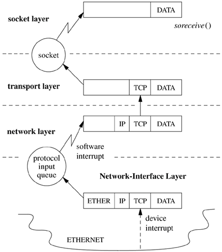
Once the packet has been queued by the device's interrupt thread, the swi_net thread is responsible for handling the packet. This handler is a thread in the kernel whose sole job is to read packets off the queue, and if a message received by a communication protocol is destined for a higher-level protocol, this protocol is invoked directly. If the message is destined for another host (i.e., following the forward path) and the system is configured as a router, the message may be returned to the network-interface layer for retransmission. Communication Protocols A network protocol is defined by a set of conventions, including packet formats, states, and state transitions. A communication-protocol module implements a protocol and is made up of a collection of procedures and private data structures. Protocol modules are described by a protocol-switch structure that contains the set of externally visible entry points and certain attributes, shown in Figure 12.2. The socket layer interacts with a communication protocol solely through the latter's protocol-switch structure, recording the address of the structure in the socket's so_proto field. This isolation of the socket layer from the networking subsystem is important in ensuring that the socket layer provides users with a consistent interface to all the protocols supported by a system. When a socket is created, the socket layer looks up the domain for the protocol family to find the array of protocol-switch structures for the family (see Section 11.4). A protocol is selected from the array based on the type of socket supported (the pr_type field) and optionally a specific protocol number (the pr_protocol field). The protocol switch has a back pointer to the domain (pr_domain). Within a protocol family, every protocol capable of supporting a socket directly (for example, most transport protocols) must provide a protocol-switch structure describing the protocol. Lower-level protocols such as network-layer protocols may also have protocol-switch entries, although whether they do can depend on conventions within the protocol family. Figure 12.2. Protocol-switch structure. 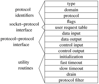
Before a protocol is first used, the protocol's initialization routine is invoked. Thereafter, the protocol will be invoked for timer-based actions every 200 milliseconds if the pr_fasttimo() entry is present, and every 500 milliseconds if the pr_slowtimo() entry point is present. In general, protocols use the slower timer for most timer processing; the major use of the fast timeout is for delayed-acknowledgment processing in reliable transport protocols. The pr_drain() entry is provided so that the system can notify the protocol if the system is low on memory and would like any noncritical data to be discarded. Finally, the pr_pfil() entry gives a hook for packet-filtering calls, which allow a system administrator to drop or modify packets as they are processed by the networking subsystem. Protocols may pass data between their layers in chains of mbufs (see Section 11.3) using the pr_input() and pr_output() routines. The pr_input() routine passes data up toward the user, whereas the pr_output() routine passes data down toward the network. Similarly, control information passes up and down via the pr_ctlinput() and pr_ctloutput() routines. The table of user request routines, pr_usrreqs(), is the interface between a protocol and the socket level; it is described in detail in Section 12.2. In general, a protocol is responsible for storage space occupied by any of the arguments passed downward via these procedures and must either pass the space onward or dispose of it. On output, the lowest level reached must free space passed as arguments; on input, the highest level is responsible for freeing space passed up to it. Auxiliary storage needed by protocols is allocated from the mbuf pool. This space is used temporarily to formulate messages or to hold variable-sized socket addresses. (Some protocols also use mbufs for data structures such as state control blocks, although many such uses have been converted to use malloc() directly.) Mbufs allocated by a protocol for private use must be freed by that protocol when they are no longer in use. The pr_flags field in a protocol's protocol-switch structure describes the protocol's capabilities and certain aspects of its operation that are pertinent to the operation of the socket level; the flags are listed in Table 12.1. Protocols that are connection based specify the PR_CONNREQUIRED flag, so that socket routines will never attempt to send data before a connection has been established. If the PR_WANTRCVD flag is set, the socket routines will notify the protocol when the user has removed data from a socket's receive queue. This notification allows a protocol to implement acknowledgment on user receipt and also to update flow-control information based on the amount of space available in the receive queue. The PR_ADDR field indicates that any data placed in a socket's receive queue by the protocol will be preceded by the address of the sender. The PR_ATOMIC flag specifies that each user request to send data must be done in a single protocol send request; it is the protocol's responsibility to maintain record boundaries on data to be sent. This flag also implies that messages must be received and delivered to processes atomically. The PR_RIGHTS flag indicates that the protocol supports the transfer of access rights; this flag is currently used by only those protocols in the local communication domain. Connection-oriented protocols that allow the user to set up, send data, and tear down a connection all in a single sendto call have the PR_IMPLOPCL flag set. The PR_LASTIIDR flag is used by secure protocols, such as IPSec, where several headers must be processed to get at the actual data. Table 12.1. Protocol flags.Flag | Description |
|---|
PR_ATOMIC | messages sent separately, each in a single packet | PR_ADDR | protocol presents address with each message | PR_CONNREQUIRED | connection required for data transfer | PR_WANTRCVD | protocol notified on user receipt of data | PR_RIGHTS | protocol supports passing access rights | PR_IMPLOPCL | implied open/close | PR_LASTHDR | used by secure protocols to check for last header |
Network Interfaces Each network interface configured in a system defines a link-layer path through which messages can be sent and received. A link-layer path is a path that allows a message to be sent via a single transmission to its destination, without network-level forwarding. Normally, a hardware device is associated with this interface, although there is no requirement that one be (e.g., all systems have a software loopback interface). In addition to manipulating the hardware device, a network-interface module is responsible for encapsulation and decapsulation of any link-layer protocol header required to deliver a message to its destination. For common interface types, the link-layer protocol is implemented in a separate sublayer that is shared by various hardware drivers. The selection of the interface to use in sending a packet is a routing decision carried out at the network-protocol layer. An interface may have addresses in one or more address families. Each address is set at boot time using an ioctl system call on a socket in the appropriate domain; this operation is implemented by the protocol family after the network interface verifies the operation with an ioctl entry point provided by the network interface. The network-interface abstraction provides protocols with a consistent interface to all hardware devices that may be present on a machine. An interface and its addresses are defined by the structures shown in Figure 12.3 (on page 480). As interfaces are found at startup time, the ifnet structures are initialized and are placed on a linked list. The network-interface module generally maintains the ifnet interface data structure as part of a larger structure that also contains information used in driving the underlying hardware device. Similarly, the ifaddr interface address structure is often part of a larger structure containing additional protocol information about the interface or its address. Because network socket addresses are variable in size, each protocol is responsible for allocating the space referenced by the address, mask, and broadcast or destination address pointers in the ifaddr structure. Figure 12.3. Network-interface data structures. 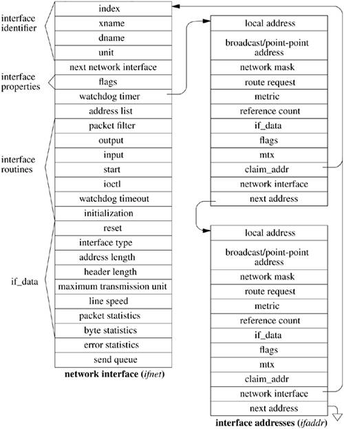
Each network interface is identified in two ways: a character string identifying the driver plus a unit number for the driver (e.g. fxpO) and a binary systemwide index number. The index is used as a shorthand identifier for example, when a route that refers to the interface is established. As each interface is found during system startup, the system creates an array of pointers to the ifnet structures for the interfaces. It can thus locate an interface quickly given an index number, whereas the lookup using a string name is less efficient. Some operations, such as interface address assignment, name the interface with a string for the user's convenience because performance is not critical. Other operations, such as route establishment, pass a newer style of identifier that can use either a string or an index. The new identifier uses a sockaddr structure in a new address family, AF_LINK, indicating a link-layer address. The family-specific version of the structure is a sockaddr_dl structure, shown in Figure 12.4, which may contain up to three identifiers. It includes an interface name as a string plus a length, with a length of zero denoting the absence of a name. It also includes an interface index as an integer, with a value of zero indicating that the index is not set. Finally, it may include a binary link-level address, such as an Ethernet address, and the length of the address. An address of this form is created for each network interface as the interface is configured by the system and is returned in the list of local addresses for the system along with network protocol addresses (see later in this subsection). Figure 12.4 shows a structure describing an Ethernet interface that is the first interface on the system; the structure contains the interface name, the index, and the link-layer (Ethernet) address. Figure 12.4. Link-layer address structure. The box on the left names the elements of the sockaddr_dl structure. The box on the right shows sample values for these elements for an Ethernet interface. The sdl_data array may contain a name (if sdl_nlen is nonzero, a link-layer address (if sdl_alen is nonzero), and an address selector (if sdl_slen is nonzero). For an Ethernet, sdl_data contains a three-character name followed by a unit number, fxpO, followed by a 6-byte Ethernet address. 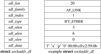
The interface data structure includes an if_data structure, which contains the externally visible description of the interface. It includes the link-layer type of the interface, the maximum network-protocol packet size that is supported, and the sizes of the link-layer header and address. It also contains numerous statistics, such as packets and bytes sent and received, input and output errors, and other data required by network-management protocols. The state of an interface and certain externally visible characteristics are stored in the if_flags field described in Table 12.2 (on page 482). The first set of flags characterizes an interface. If an interface is connected to a network that supports transmission of broadcast messages, the IFF_BROADCAST flag will be set, and the interface's address list will contain a broadcast address to be used in sending and receiving such messages. If an interface is associated with a point-to-point hardware link (e.g., a leased line circuit), the IFF_POINTOPOINT flag will be set, and the interface's address list will contain the address of the host on the other side of the connection. (Note that the broadcast and point-to-point attributes are mutually exclusive.) These addresses and the local address of an interface are used by network-layer protocols in filtering incoming packets. The IFF_MULTICAST flag is set by interfaces that support multicast packets in addition to IFF_BROADCAST. Multicast packets are sent to one of several group addresses and are intended for all members of the group. Table 12.2. Network interface flags.Flag | Description |
|---|
IFF_UP | interface is available for use | IFF_BROADCAST | broadcast is supported | IFF_DEBUG | enable debugging in the interface software | IFF_LOOPBACK | this is a software loopback interface | IFF_POINTOPOINT | interface is for a point-to-point link | IFF_SMART | interface manages its own routes | IFF_RUNNING | interface resources have been allocated | IFF_NOARP | interface does not support ARP | IFF_PROMISC | interface receives packets for all destinations | IFF_ALLMULTI | interface receives all multicast packets | IFF_OACTIVE | interface is busy doing output | IFF_SIMPLEX | interface cannot receive its own transmissions | IFF_LINKO | link-layer specific | IFF_LINK1 | link-layer specific | IFF_LINK2 | link-layer specific | IFF_MULTICAST | multicast is supported | IFF_POLLING | interface is in polling mode | IFF_PPROMISC | user-requested promiscuous mode | IFF_MONITOR | user-requested monitor mode | IFF_STATICARP | interface only uses static ARP |
Additional interface flags describe the operational state of an interface. An interface sets the IFF_RUNNING flag after it has allocated system resources and has posted an initial read on the device that it manages. This state bit avoids multiple allocation requests when an interface's address is changed. The IFF_UP flag is set when the interface is configured and is ready to transmit messages. The IFF_OACTIVE flag is used to coordinate between the if_output and if_start routines, described later in this subsection; it is set when no additional output may be attempted. The IFF_PROMISC flag is set by network-monitoring programs to enable promiscuous reception: when they wish to receive packets for all destinations rather than for just the local system. Packets addressed to other systems are passed to the monitoring packet filter but are not delivered to network protocols. The IFF_ALLMULTI flag is similar, but it applies to only multicast packets and is used by multicast forwarding agents. The IFF_SIMPLEX flag is set by Ethernet drivers whose hardware cannot receive packets that they send. Here, the output function simulates reception of broadcast and (depending on the protocol) multicast packets that have been sent. Finally, the IFF_DEBUG flag can be set to enable any optional driver-level diagnostic tests or messages. Three flags are defined for use by individual link-layer drivers (IFF_LINKO, IFF_LINK1, and IFF_LINK2). They can be used to select link-layer options, such as Ethernet medium type. Interface addresses and flags are set with ioctl requests. The requests specific to a network interface pass the name of the interface as a string in the input data structure, with the string containing the name for the interface type plus the unit number. Either the SIOCSIFADDR request or the SIOCAIFADDR request is used initially to define each interface's addresses. The former sets a single address for the protocol on this interface. The latter adds an address, with an associated address mask and broadcast address. It allows an interface to support multiple addresses for the same protocol. In either case, the protocol allocates an ifaddr structure and sufficient space for the addresses and any private data and links the structure onto the list of addresses for the network interface. In addition, most protocols keep a list of the addresses for the protocol. The result appears somewhat like a two-dimensional linked list, as shown in Figure 12.5. An address can be deleted with the SIOCDIFADDR request. Figure 12.5. Network-interface and protocol data structures. The linked list of ifnet structures appears on the left side of the figure. The ifaddr structures storing the addresses for each interface are on a linked list headed in the ifnet structure and shown as a horizontal list. The ifaddr structures for most protocols are linked together as well, shown in the vertical lists headed by pf1_addr and pf2_addr. 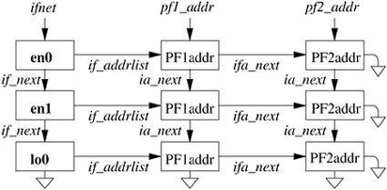
The SIOCSIFFLAGS request can be used to change an interface's state and to do site-specific configuration. The destination address of a point-to-point link is set with the SIOCSIFDSTADDR request. Corresponding operations exist to read each value. Protocol families also can support operations to set and read the broadcast address. Finally, the SIOCGIFCONF request can be used to retrieve a list of interface names and protocol addresses for all interfaces and protocols configured in a running system. Similar information is returned by a newer mechanism based on the sysctl system call with a request in the routing protocol family (see Sections 12.5 and 14.6). These requests permit developers to construct network processes, such as a routing daemon, without detailed knowledge of the system's internal data structures. Each interface has a queue of packets to be transmitted and routines used for initialization and output. The if_output() routine accepts a packet for transmission and normally handles link-layer encapsulation and queueing that are independent of the specific hardware driver in use. If the IFF_OACTIVE flag is not set, the output routine may then invoke the driver's if_start() function to begin transmission. The start function then sets the IFF_OACTIVE flag if it is unable to accept additional packets for transmission; the flag will be cleared when transmission completes. The if_done() entry point is provided as a callback function for use when the output queue is emptied. This facility is not yet used, but it is intended to support striping of data for a single logical interface across multiple physical interfaces. An interface may also specify a watchdog timer routine and a timer value that (if it is nonzero) the system will decrement once per second, invoking the timer routine when the value expires. The timeout mechanism is typically used by interfaces to implement watchdog schemes for unreliable hardware and to collect statistics that reside on the hardware device. |