Planning Activities
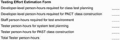
| Now we want to discuss the process of planning for testing. We will present a set of planning documents that are useful in organizing information such as specific test cases. We will relate these documents to how and when testing activities are scheduled. These planning documents are working documents. After each increment, and sometimes after a specific iteration, these documents are reviewed and revised. Risks are updated as are priorities and schedules. Scheduling Testing ActivitiesClass tests are scheduled at the discretion of a developer as they become useful or necessary. A class test is useful during coding when the developer wishes to identify missing features or verify the correctness of part of an implementation. A class test becomes necessary when a component is to be added to the code base. The class may not be completely developed, but the behaviors that it does provide should be complete and correct. Integration tests are typically scheduled at specific intervals, usually at the end of major iterations that signal the completion of an increment and/or just prior to releases. Alternatively, integration may be an ongoing, highly iterative process that occurs each evening. Integration test cycles can also be scheduled to coincide with deliveries from major outside vendors, such as a new version of a base framework. System tests will be performed on major deliverables at specified intervals throughout the project. This schedule is usually specified in the project plan since there is often a need to coordinate with a separate organization that may be providing testing services to numerous projects simultaneously. EstimationPart of scheduling is estimating the resources cost, time, and personnel that will be needed to support the plans being made. This is not easy and we have no magic formulas. In this section we will discuss the factors levels of coverage, domain type, equipment required, organization model, and testing effort that should be considered. Levels of CoverageThe more comprehensive the level of coverage, the more resources that will be required. Estimates of the amount of code written to support testing vary. Beizer estimates from 2% to 80% of the application size [Beiz90]. Other estimates are even higher. We have had success in considering each system use case as a unit measure. By estimating the amount of effort for one use case (perhaps through a prototyping effort), you can construct the estimate for the complete system. Some use cases are much broader in scope or more abstract in level. Choose a set of use cases that are at approximately the same level of detail in the model and use those for estimating. If two use cases extend another more general case, then use either the two specific or the one more general use case, but not both. Domain TypeOften more technically oriented software embodies much of its complexity in the programming logic, while the program inputs are fairly simple. On the other hand, systems that are data intensive often have relatively simple logic, but the test cases require large amounts of effort to construct. The amount of effort required to construct a complete test case including complete inputs and correct outputs can vary considerably. A simple program that queries a large database requires much time to build the data set and much time to verify that the answer produced is correct. Equipment RequiredSystem testing should be conducted in an environment as close as possible to the deployment environment. Even some aspects of class testing may require either special hardware environments or a hardware simulator. The cost of installing and maintaining the equipment or constructing the simulator must be included in any estimate. Organization ModelWe have discussed a couple of schemes that are commonly used to staff the testing process. Our experience has shown that the more independent the testers are from the development organization, the more thorough the tests are. However, this independence requires a longer learning curve and thus more expense. Common estimates are that one independent tester can only handle the output of two to three developers. Conversely, tying the testers to the development organization (or using personnel from the development team to test) reduces the time required to learn the system. Specifications are seldom completely written down or up-to-date. If a tester is a person who also participates in discussions about the solution, then that tester can understand the implicit assumptions in a specification more completely. However, it may be more difficult for testers to be as rigorous or objective if they become too closely tied to the development effort. Consider using a buddy approach to class testing. It provides much of the objectivity that makes testing most effective. Rather than have developers test their own classes, form buddy groups. Two developers swap code with each other and test. The advantage is more thorough testing. Since the tester is another developer who is also developing closely related code, this person can be productive much more quickly than a person from the independent test team who must first learn about the context. Testing Effort EstimateEstimation techniques almost always rely on historical data to make projections. We will not take the space here to discuss these techniques. Figure 3.12 provides a very simple form to use in accounting for all of the hours required for the various testing activities. As we proceed through the book, we will provide more detailed guidance for completing the various sections of the form. Figure 3.12. A testing effort estimation form
For now we can summarize much of this by using historical data to determine the cost of producing a single class. From the list in Figure 3.12 we can identify the classes that will have to be constructed:
The total number of classes times the effort per class gives the effort for all testing classes. Planning is addressed in Planning Effort on page 105. A Process for Testing BricklesIn this section we will illustrate the following five dimensions by applying each of them to our case study.
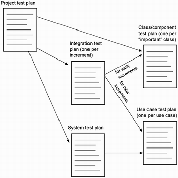
Document TemplatesWe will discuss a project test plan, a component test plan, an integration test plan, a use case test plan, and a system test plan. The relationships among these plans are illustrated in Figure 3.13. Each arrow in the figure indicates that the pointed-to document is included by the reference in the document that originates the arrow. Figure 3.13. Relationships among test plans
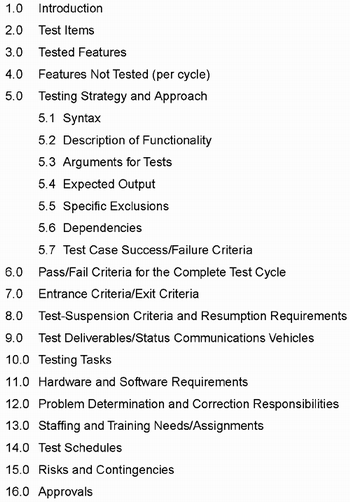
We will present these in template format. This is a useful approach for several reasons. Except for the system test plan, there will be multiple instances of these documents. A template ensures consistency of form and content among these independent, but related, documents. The more of the document that can be incorporated into the template, the less effort a developer will need to expend in producing the multiple instances. The template approach will also simplify the inspection process since each document will follow the same style, this specific content can be located quickly. The IEEE test plan outline in Figure 3.14 lists the basic sections for a test plan regardless of level. We want to address those that are most important in an incremental, iterative object-oriented software development environment. In the following test plans we will not name the sections exactly according to the outline, but we will include the basic required information. The following test plan items are particularly important:
Figure 3.14. The IEEE 829 Standard Test Plan outline
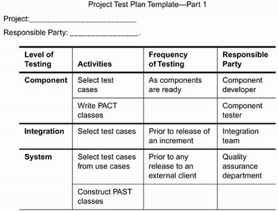
Project Test PlanThe purpose of this document is to summarize the testing strategy that is to be employed for the project. It should define the steps in the development process at which testing will occur, the frequency with which the testing should occur, and who is responsible for the activity. The project test plan may be an independent document or it may be included in either the overall project plan or the project's quality assurance plan. Because its format is so variable and its content quite flexible, we will only provide a couple of tables below that summarize the information usually included. The table in Figure 3.15 summarizes the activities that are required, the frequency with which each activity will be employed, and the entity that is responsible for this phase of testing. More specific information about each of these is included in the detailed plan for that level. Figure 3.15. Project test plan template Part 1
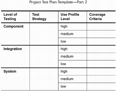
A second table, in Figure 3.16, associates each of the phases with a specific strategy for that phase. We will describe several testing strategies in the appropriate chapters and you can pick your favorite. This table also records project standards for adequate testing for each risk level within the three phases. Figure 3.16. Project test plan template Part 2
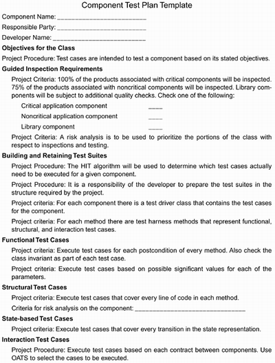
Component Test PlanThe purpose of a component test plan is to define the overall strategy and specific test cases that will be used to test a certain component. One test plan will be completed on each component that is sufficiently significant to require isolated testing. We present here a template that we have used successfully. Two types of guiding information are included in the template: project criteria and project procedures. These are included to serve as handy reminders and to avoid the need to produce a component test plan that summarizes all of the component-testing information for the project. Project criteria are standards that have been agreed upon as to how thoroughly each component will be tested. For example, project criteria might call for 100% of the postconditions on modifier methods to be tested. These criteria should be providing more detail on the coverage criteria defined in the project test plan. Project procedures identify techniques that have been agreed upon as the best way to handle a particular task. For example, constructing a PACT class (see Chapter 7) for each component that will be tested is a project procedure. These procedures will provide the details of the test strategies that were identified in the project test plan. We will give a brief comment on each section of the template. Figure 3.17 shows the template. We will not comment on sections that simply record information such as the name of the component. Italicized portions will represent actual entries in the template. Figure 3.17. A component test plan template
Objectives for the Class. The developer will replace this paragraph with a prioritized list of objectives for the component. For example, this component is an element of the basic framework for the application and is intended as a high-level abstraction from which the more specific variants are derived. Guided Inspection Requirements. Project Criteria: 100% of the products associated with critical components will be inspected. 75% of the products associated with noncritical components will be inspected. Library components will be subject to additional quality checks. Project Procedure: Risk analysis is used to prioritize the portions of the class with respect to inspections and testing. Building and Retaining Test Suites. The developer will replace this paragraph with information about
Functional Test Cases. The developer will replace this paragraph with information about
Structural Test Cases. The developer will replace this paragraph with information about
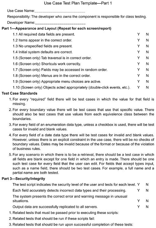
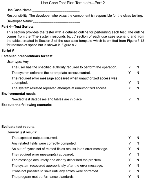
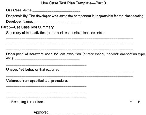
State-Based Test Cases. The developer will replace this paragraph with information about the state representation for the class. Refer to the state diagram if available. Interaction Test Cases. The developer will replace this paragraph with information about which messages will be tested based on the OATS selection process (see Chapter 6). Use Case Test PlanThe purpose of this plan is to describe the system-level tests to be derived from a single use case. These plans are incorporated by reference into both the integration and system test plans. Figures 3.18, 3.19, and 3.20 show portions of the use case test plan template. Other parts will be shown in Chapter 9. Figure 3.18. Use case test plan template Part 1
Figure 3.19. Use case test plan template Part 2
Figure 3.20. Use case test plan template Part 3
The test plans can be constructed in a modular fashion following the same pattern as the dependencies between the "partial" use cases. Use case models can be structured in the same way class diagrams are. The includes and extends relations provide the means for decomposing the use cases into "partial" use cases as described in Chapter 2. The partial use cases are combined using the relationships to form what we refer to as "end-toed" use cases. We identify three levels of use cases: high-level, end-to-end system, and functional sub-use cases. The high-level use cases are abstract use cases that are the basis for being extended to end-to-end use cases. The functional sub-use cases are aggregated into end-to-end system-level use cases. We have built actual test scripts, in the scripting language of test tools, that use the generalization/specialization relationship between the high-level and end-to-end use cases. These test scripts also aggregate fragments of test scripts from the functional sub-use cases. By having these three levels, our projects are more manageable and our test scripts are more modular. The project for which this was the template also identified two different "types" of use cases: functionality and report use cases. Functionality use cases modified the data maintained by the system in some way. Report use cases accessed information in the system, summarized it, and formatted it for presentation to the user. These differences led to different numbers of tests for security and persistence. You may identify other groupings of the use cases that are useful to your project. Integration Test PlanThe integration test plan is particularly important in an iterative development environment. Specific sets of functionality will be delivered before others. Out of these increments the full system slowly emerges. One implication from this style of development is that the integration test plan changes character over the life of the project more than the component or the system test plans. The components that are integrated in early increments may not directly support any end-user functionality and hence none of the use cases can be used to provide test cases. At this stage the best source is the component test plans for the aggregated components. These are used to complete the component test plan for the component that integrates these objects. After a number of increments have been delivered, the functionality of the integrated software begins to correspond to system-level behavior. At that time the best source of test cases is the use case test plans. In both cases, the test cases are selected based on the degree to which the test case requires behavior across all of the parts that are being integrated. Small, localized behavior should have already been tested. This means that the tests should be more complex and more comprehensive than the typical component tests. In a properly integrated object-oriented system, there will be certain objects that span a number of other objects in the build. Choosing tests from the test plans for those components will often be sufficient for good integration test cases. Because of this dependence on other test cases, we do not provide a separate template for the integration test plan. Its format will follow that of the system test plan in that it will be a mapping of which individual test plans are combined to form the integration test plan for a specific increment. System Test PlanThe system test plan is a document that summarizes the individual use case test plans and provides information on additional types of testing that will be conducted at the system level. In each of the techniques chapters, we will describe life-cycle testing as one technique that can be applied at the system level and also at the individual component level. For our purposes here, we will provide a chart, see Figure 3.21, that maps the use-case test plans to specific system tests. Most of the information required by the IEEE test plan format will have already been provided by the individual use case test plans. Figure 3.21. System test plan
Iteration in PlanningThe iterations in the development process affect how planning is carried out. Changes in product or increment requirements at least require that test plans be reviewed. In many cases they will also need to be modified. We keep traceability matrices to assist with this iterative modification. If the development organization receives requirements in a traditional form, we build a requirements-to-use-case mapping matrix. This is often just a spreadsheet with requirement IDs in the vertical axis and use case IDs on the horizontal axis. An entry in a cell indicates that the use case provides functionality related to or constrained by the requirement. We also maintain a second matrix in which we relate each use case to a set of packages of classes. An entry in a cell indicates that the package provides classes that are used to realize the use case. When a use case is changed, the owners of packages are informed. They check the functionality they are providing and make the necessary changes to their code. This triggers changes in several levels of test cases and perhaps test plans as well. Planning EffortThe effort expended in planning depends on a few things:
Each of these values will require the establishment of a baseline on which to base estimates. Test MetricsTest metrics include measures that provide information for evaluating the effectiveness of individual testing techniques and the complete testing process. Metrics are also used to provide planning information such as estimates of the effort required for testing. To create these final measures we need measures of coverage and complexity to form the basis of effectiveness and efficiency metrics. Coverage is a testing term that indicates which items have been touched by test cases. We will discuss a number of different coverage measures during the presentation of the testing techniques discussed in the book. Examples include the following:
Coverage metrics are stated in terms of the product being tested rather than the process we are using to test it. This gives us a basis by which we can describe how "thoroughly" a product has been tested. For example, consider the situation in which one developer uses every logical clause from every postcondition as a source for test cases, while a second developer only uses the "sunny-day" clauses[8] from the postconditions as the source for tests. The second developer is not testing as thoroughly as the first as evidenced by what fraction of the postcondition clauses are being covered.
Coverage can be combined with complexity to give an accurate basis for estimating the effort needed to test a product. That is, as the software becomes more complex, it will be much more difficult to achieve a specified level of coverage. Several measures of complexity are available:
By collecting performance data over time, a project or company can develop a baseline from which projections can be made for planning a new project. The testing process is effective if it is finding faults. It is efficient if it is finding them with as few resources as possible. We will discuss a couple of measures that give information about both of these. The number of defects/developer-hour metric determines the yield of the process while the developer hours/number of defects metric provides a measure of the cost of the process. These numbers are dependent on the tools that are used to construct tests as well as the levels of coverage sought, so each company will need to baseline their process and collect actual performance data before using these numbers for planning purposes. The effectiveness of the testing process is evaluated by collecting data over the complete development life cycle. Consider a fault that is injected into an application during design. The sooner that defect is detected, the more effective is the testing process. The efficiency of the testing process is measured by considering the intervals between the development phase in which the defect is injected and the phase in which it is detected for all defects. The perfectly effective testing process finds every defect in the same development phase in which it was injected. If defects injected at design time are not being detected until code testing, the testing technique used during the design of the system should be modified to search specifically for the types of faults that are not being detected in a timely manner. |
EAN: 2147483647
Pages: 126
