Examining Network Models
Network models are just abstract ways for engineers to describe how all of the protocols, hardware, and physical media of a network interact. The layered structure of models provides a simple visual reference for what’s going on at all levels of a network.
Unless you’re going to become an engineer, or intend to develop network software, you really don’t need to kill yourself trying to learn network models. In fact, in my experience most professionals have little more than a trivial understanding of the various reference models; they just don’t need it.
Keeping this in mind, I’m presenting you with a brief and simplified explanation of three network models. This is just so that you’ll be able to grasp related terms and have a better understanding of what different network components do.
Deconstructing the OSI reference model
The Open Systems Interconnect (OSI) reference model is the most widely used model for describing communications across networks. In practice, most software and hardware vendors never implemented the OSI model. It was never widely supported, and engineers mostly use it as a teaching tool. If you ever take a networking class or information systems course, you will learn this model.
The OSI model describes network communications using seven layers (see Figure 2-2). These layers are (in reverse order):
Application Layer (layer 7)
Presentation Layer (layer 6)
Session Layer (layer 5)
Transport Layer (layer 4)
Network Layer (layer 3)
Data Link (MAC) Layer (layer 2)
Physical Layer (layer 1)
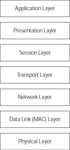
Figure 2-2: The OSI reference model
Each of the layers assigns functions relating to network communications. I present the layers top-down with the top application layer (layer 7) being that which is closest to the user, and the bottom physical layer (layer 1) being where the actual transmission of electrical impulses takes place. A brief description of each layer follows.
Application layer
As a user, you interact with this layer. Some of the functions that reside at this layer are opening, closing, checking e-mail, and deleting files.
Presentation layer
The presentation layer manages the way systems encode data. Encryption and decryption of transmitted data occur at this layer.
Session layer
This layer describes managing communications between nodes. In real-world systems (remember, OSI is primarily a teaching model), most of this occurs at the transport layer.
Transport layer
This layer describes the processes for managing communications and providing for the integrity of transmitted data. Riveting stuff. Are you still awake?
Network layer
This layer describes the routing of communications. On a TCP/IP network, a router operates on this layer.
Data link layer
This layer is responsible for maintaining the validity and integrity of communication between nodes on a network. Transmitted data may pass through many nodes before reaching its destination. At this layer, each node checks that the data is intact and valid before passing it on to the next node.
Physical layer
This is where the physical operation of the network occurs, and devices pass around data in the form of electrons. The physical layer describes the actual network, whether it’s Ethernet, fiber-optic, or, in the case of a WLAN, radio frequencies.
Comparing the TCP/IP model
In contrast with the OSI model, engineers actually use the TCP/IP model, which uses the TCP/IP suite described later in this chapter (see Figure 2-3). It has four layers — compared to the seven in the OSI model — that sit on the physical layer (not described by the TCP/IP model). The four layers of the TCP/IP model are (again, in reverse order):
Application Layer (layer 4)
Transport Layer (layer 3)
Network Layer (layer 3)
Data Link (MAC) Layer (layer 1)
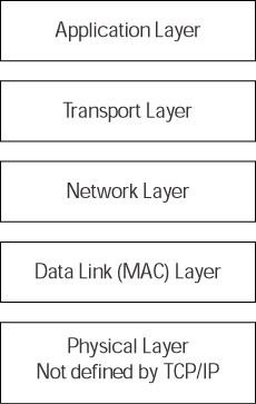
Figure 2-3: The TCP/IP reference model
Like the OSI model, each of the TCP/IP layers assigns functions relating to network communications. A brief description of each layer follows:
Application layer
Just like the OSI model, this is where the user interacts with network programs. TCP/IP client/server applications communicate on this layer.
Transport layer
This layer uses two protocols — Transmission Control Protocol (TCP) and the User Datagram Protocol (UDP) — to manage communication between hosts. TCP ensures that data arrives at its destination without errors or missing packets, UDP does not provide error checking and is used for maintaining connections between networked applications.
Network layer
This layer uses Internet Protocol (IP) to route data across connected networks.
Data link (MAC) layer
This layer describes the transmission of data across a local network. This occurs once the network layer has routed data across interconnected networks, such as the Internet, and it has arrived at its destination network. This layer also describes transmission of data that never leaves the local network. In the TCP/IP model, engineers often refer to this layer as the network interface layer or the media access control (MAC) layer.
The TCP/IP model describes how to route data across networks without worrying what the actual physical network is.
Examining Wi-Fi layers
The 802.11x standards define the layers upon which communication takes place on a WLAN. 802.11 defines three layers of the WLAN network model: network infrastructure, media access control, and physical (see Figure 2-4). The layers of a WLAN define how a WLAN operates. Higher layers defined by the TCP/IP suite handle the routing and delivery of data. To oversimplify it a bit, the TCP/IP model just described runs on top of the WLAN model.
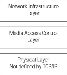
Figure 2-4: The WLAN Layers
Network infrastructure layer
This layer describes how devices communicate on a WLAN, and how the network authenticates users and determines who is an authorized user.
Media access control layer
This layer describes how computers on the network gain access to receive and transmit data and how they maintain communication between nodes after authentication has succeeded.
Physical layer
The physical layer includes all hardware components and wireless connections and describes the electrical interface to the network. It determines how nodes transmit and receive streams of data on a radio frequency channel.
The physical layers of a WLAN are all you need to remember. When shopping for equipment, you’ll be selecting Wi-Fi equipment based on one of the three 802.11x physical standards: 802.11b, 802.11a, or 802.11g.
EAN: 2147483647
Pages: 145