3.9 Developing Supplemental Performance Requirements
3.9 Developing Supplemental Performance Requirements
Three supplemental performance requirements were introduced in Chapter 2: operational suitability, supportability, and confidence. These performance requirements are part of the overall set of operations and support elements shown in Figure 3.19. Operational suitability is a measure of how well the network design can be configured, monitored, and adjusted by the customer's operators. Supportability is a measure of how well the customer can keep the system performing, as designed, over the entire life of the system. Confidence is a measure of the ability of the network to deliver data without error or loss at the required throughput.
| Operations and Support | |
|---|---|
| Operations | Support |
| Management | Management |
| Personnel | Maintenance Support |
| Tools | Technical Documentation |
| Consumables | Storage |
| Transportation | Supply Support |
| Leasing | Modifications |
| Facilities | |
Figure 3.19: Elements of operations and support.
3.9.1 Operational Suitability
Ensuring that your customer can operate the planned network is almost never an easy task and one that the customer never thinks about until asked. Two major factors influence the operational suitability: network architecture/design and the quality of the human operators.
It is possible to develop a network that cannot be operated consistently and effectively. Complex minute-to-minute adjustments can swamp even the most competent staff. The lack of any effective monitoring tools or control systems to integrate actions across geographically dispersed sites can transform the most advanced design into a dysfunctional mass of cable and computers and recriminations and lawsuits. Development of the network must consider network management that permits the operators to adjust the network and to reconfigure it when they need to. If they need to do it every few minutes, network management must be easy to operate and present the controls in an easily understood way.
An undersized operations staff can be quickly worn out and frustrated by a network that requires constant and precise tending. Components that never need adjustment except when they are installed do not need to clutter the integrated control console. System monitoring is essential to adjusting system performance by its operators; displays must be accessible and the data displayed using well-understood representations. Should there be a single (or redundant) operations console, or should the system be operated from any Web browser within the network? To what degree is automation incorporated to reduce the operators' workload or to improve the response to changing conditions over what a human can provide? Is system adjustment so infrequent that no integrated control system is required? These issues are discussed in detail in Chapter 7.
A Marine colonel who managed a major system development program kept a picture on his wall of the most pathetic, bedraggled Marine recruit he had ever seen. This Sad Sack was standing on an empty parade ground holding a bag of trash in one hand and a stick with a nail in the other to use to pick paper off the ground. The caption read, "Remember. No matter what you dream, what you plan, this man must execute." Operators are more essential than any technology to successful communications over a network.
In most cases a new network design is the result of obsolescence or an order-of-magnitude increase in performance requirements. These new components and tools are likely to be radically different than those currently in use by the customer, so the current staff is also likely to be obsolete or inadequately sized. It is almost always necessary to retrain or replace the operations staff during the transition period; it may also be necessary to radically expand that staff if a much larger scale network is required to meet the customer's growing needs for communications. Keep in mind that replacement of humans in the system is much more difficult than replacing routers with switches or multimode fiber with Category 6 copper cable.
These are activities that must be planned before the transition and implementation period and usually have a significant lead time, but they must be accomplished before the network achieves its initial operational capability (IOC). It is essential that the network engineer systematically uncover the customer's needs and constraints in these areas, document them, and then factor them into the design. These factors have a significant influence on the degree of automation that is incorporated into the design and the assumed skill level needed to operate the network.
Presenting this information during the design review ensures that the customer understands what it takes to operate the network and that any changes to the design (e.g., increased automation to compensate for a small staff) are made early in the process rather than cobbled onto the final product or into an endless cycle of change orders during delivery.
One of the key benefits to a skilled and motivated operations staff is their ability to apply the basic network architecture/design to meet new situations that were unforeseen during the development phase. Lacking this set of skills, the network engineer's design must be even more robust and have a high degree of automation to ensure that the system is protected from the operators. A set of operators who respect the documented procedures and understand the system architecture and how the components work together can be trusted to improvise when new situations occur, as they always do. A set of unskilled operators requires a system design that is constraining to ensure ongoing performance.
A common customer edict is that the new network be operated with the same personnel as the old network or that, as a minimum, the operations staff be no more expensive than the current staff. It is essential that the design engineer meet the operations staff to develop an opinion about their skill level ability to understand new technologies and to adopt new procedures and tools. There is a trade-off between system automation and workforce, with the trade-off being that lesser qualified operators can be used. Some operations personnel are unwilling or incapable of learning to operate the new systems, so new personnel must be brought in to perform these functions. Requirements for operator selection, qualification, and training (both initial and refresher) may seem burdensome but are absolutely necessary. If the requirement to retain the same staff is hard and fast, then system design using advanced components and architectures must take this into account.
Operational suitability requirements must be collected from interviews with the operators and owners. If new staff is going to be used, then interviews with people of approximately the same skill level should be substituted; these must be operators, not the design engineering team, which may not have the experience necessary to see how the system looks from the operator's point of view.
Articulating a concept of operations is very useful in defining the customer's needs, conveying the overall approach to the design team, and ensuring that the customer has fully conveyed his or her strategy to the designers. Such a document should be no more than 10 pages long and address the operator skill level and shift work organization, the tempo of operations, the degree to which the operator is expected to reconfigure the system and how it is done. Some additional questions to be considered during the requirements analysis process are as follows:
-
How is the operator going to monitor performance to ensure that he or she detects failures, faults, or outages before the customer does, or does the operator rely on the users to detect faults and report them?
-
How does the end user interact with the system and the operators, including reporting problems, and how are these reports tracked and responses provided? If multiple levels of quality of service are available, how does the end user request an increase or authorize a reduction in quality of service?
-
At which point does an operations problem transition into a maintenance action, and how does this occur so that it is not neglected?
-
How does the operations staff monitor system capacity and alert management to the need to expand capacity beyond the resources available to them? What types of time-averaged trend analysis will be performed to anticipate growth of demand?
3.9.2 Supportability
A key component of the customer's satisfaction with the network, as delivered, is the ability to maintain the high level of performance achieved on the day of delivery throughout the design life of the network. A relatively unsophisticated customer will recognize the poor quality of a design and implementation only when it is frequently out of service, whereas an experienced and knowledgeable customer will examine the design carefully before authorizing implementation and will want to know if it will persistently provide quality performance for its entire life cycle. He or she will also want to know what it takes to operate the design and what it takes to support continued operations. A sophisticated customer will understand the implications of an operations concept and a support concept and will respect the designer's commitment to ongoing performance after the implementation is complete and the engineers are paid.
Supportability is driven by five major factors: (1) the RMA characteristics of the architecture/design; (2) workforce, including training and staffing levels; (3) system procedures and technical documentation; (4) tools, both standard and special; and (5) spare and repair parts.
Two classes of maintenance need to be performed on the network after it is deployed: preventive and corrective. Eventually, the maintenance requirements are defined as the design is solidified. Requirements for maintenance, during this stage of the system definition, are generally qualitative in nature:
-
All components will be located where they can be maintained in place with a minimum of disruption to the system as a whole.
-
Spare parts will be supplied to ensure replacement of any component whose failure would jeopardize mission performance.
RMA
The first step in defining RMA requirements is to articulate a representative sample of mission scenarios in which the network is going to be used; these are documented in an anecdotal narrative that describes how the usage will occur, when, what is necessary for this mission to succeed, and how important it is to network users. This includes how often and the level of priority assigned to this mission.
For example, the network described in Section 2.6.3 may have users in one building who require access to data in another building that are necessary to pay employees; this data flow path is necessary only from 4 to 5 PM on Friday afternoon so that payroll can be accomplished locally over the weekend and employees paid on Monday morning. So, this becomes mission-critical during that period and as a fall-back position may continue until the local processing must start or the payroll will not be accomplished on Monday morning, resulting in disgruntled employees and all the unpleasantness that can bring. This path is not mission-critical on Monday afternoon and could therefore fail or be shut down for maintenance at that point, provided it doesn't interfere with other functions.
One possible design consideration is to include an automated system end-to-end test before the start of this critical period that would advise the operators that a system failure has occurred, which, if not corrected, could delay their paycheck for the next week. Many architectural and design features can be incorporated, but only if the architect/designer knows how the system is going to be used.
Based on the mission scenarios, reliability block diagrams (RBDs) can be constructed, for each mission, showing serial and parallel relationships between components and the performance of the mission. During the requirements analysis phase, these are at a very high level and reflect functions to accomplish the mission, rather than components to accomplish the mission. A sample RBD is presented in Figure 3.20.
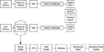
Figure 3.20: Sample reliability block diagram.
Once a design is developed and the architectural details laid out, failure modes, effects, and criticality analysis (FMECA) can be conducted to identify the primary ways in which the system can fail to perform its mission. These can then lead the designer to establish detection modes that would reduce their occurrence or accelerate the restoration of service. A template for FMECA data is shown in Figure 3.21.
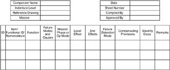
Figure 3.21: Template for FMECA data.
During the RMA analysis of the design, it is essential to remember that RMA is a tool to help the designer understand system performance so that he or she can make informed decisions.
Workforce
As with operational suitability, discussions of supportability often focus on keeping the existing workforce and/or budget the same. With the introduction of sophisticated and new technologies, this may present problems. Retraining or replacing the staff may be a strategy in the implementation that is required. Another approach is rebalancing maintenance to use contracted expert services in those areas in which the existing workforce lacks the skills. In some cases, it may make sense to outsource all maintenance, particularly when the network is a supporting function of the owner's primary line of business and he or she does not want to develop a highly skilled, expensive, internal workforce. During the requirements analysis phase, the principal objective is to get a clear picture of the customer's constraints on changing the workforce.
The personnel that will operate and maintain the network must be properly trained and possess the appropriate qualifications. One approach to defining requirements in this area is to survey the existing workforce's skills, depth, and formal training; document these features; and use them as the baseline for the new network maintenance workforce. Any changes needed then can be handled as engineering changes to the baseline requirements and the existing workforce.
Procedures and Documentation
In general, three classes of documentation are required to support the network. System and component technical documentation describes the characteristics, parts, and so on of the complete set of equipment that makes up the design. Maintenance procedures describe both the periodic preventive maintenance actions and their scheduled performance to keep the system running properly. Casualty procedures describe the abnormal (hopefully) procedures to follow when system faults occur to minimize damage to the system and to restore service as quickly as possible; prior planning for expected failure modes will do more to restore service quickly than any other investment during implementation.
Technical documentation is usually provided by the vendor of the components and is usually adequate. During implementation, the documentation should be inspected to ensure that spare and repair parts are identified so that the parts list is available if they need to be ordered quickly in response to a fault or failure. Technical documentation to describe the integration of network components is generally new material that the engineering team must generate as part of the testing, deployment, and integration of the new network.
Maintenance procedures must support both component-and system-level maintenance. This documentation must identify the frequency of and procedures for performing preventive maintenance, as well the procedures for reconfiguring the network to temporarily operate at a reduced capability while replacement components are swapped for overhaul and maintenance. Such procedures identify the tools and initial conditions required to start the procedure, testing to be performed before returning the system to a normal state, and indications that the maintenance has been performed properly or improperly.
Casualty procedures describe the planned actions for the operators to perform when a system fault occurs. These are broken down into immediate actions and supplemental actions. They are designed to place the system in a safe state and to operate it at reduced capability until the fault can be isolated and repaired with full service restored.
During the requirements analysis phase, the scope of each of these classes of documentation should be documented as a basic set of requirements.
Tools
The provisioning of common and special test equipment and tools is a consequence of the network architecture and design. At this stage, the requirements in this area represent possible constraints on the architecture and design. They should be stated in terms of the growth over the current set of tools that are possessed by the current maintenance staff. New tools should be acquired along with the components they are required to service instead of separately to ensure that they work properly with the planned network configuration.
Special test equipment, monitoring, and diagnostic software requirements should be defined during this phase in terms of their ability to improve response time to system performance issues, including failures and faults. This may represent a development effort or, as a minimum, an integration effort as the network is deployed. It would be reasonable at this point to specify the capability to detect system faults and performance degradation and to display status and key metrics at the operator's console or via a Web browser from a central server. Another requirement for consideration is the ability to monitor, reconfigure, or reset routing components using out-of-bandwidth connections, such as an analog line and a modem tied into the maintenance port on the network routing devices. This has an impact on which devices meet these requirements, and for a network with components at long distance from the operators, this may permit maintenance without physical visits.
Repair and Spare Parts
Requirements to be imposed on the spare and repair parts inventory at this stage are qualitative constraints, not a list of parts to be delivered. Some sample requirements that customers might define at this point include the following:
-
Spare and repair parts shall be stored in the network operations facility and cannot exceed, in volume, the space allocated, which is x cubic feet.
-
Initial spare and repair parts shall not exceed 15% of system acquisition costs.
-
Contract vehicles for replacement spare and repair parts shall be in place before the IOC.
Specific requirements for maintenance are generally driven by the network architecture and design and are documented in a maintenance plan, based on the design. Eventually, the spare and repair parts provisioning is derived from the actual design and a maintenance analysis of the design.
Support Concept
Definition of support concept describes the way in which the network is supported. It may help articulate the customer constraints, and it helps identify alternative approaches to support that can be accommodated in the design.
A commonly accepted maintenance support concept is the three-tier model. At the local level, or the first tier, the operators can perform a set of minimal maintenance actions. They can monitor for component failure and isolate the problem. Since they are often on-site, or at least in proximity to the components, they can handle immediate actions for system faults or casualties and some supplemental actions, such as rerouting circuits or replacing certain line-replaceable units.
The second tier is an intermediate maintenance activity, which has the ability to repair some components or to provide a place for on-site repair by the factory service representatives, if they are working locally. This tier involves staffing with specialized skills and a limited set of equipment. This is often handled via service contracts with the vendor or a third party who is sufficiently local and therefore able to arrive onsite within a short time. The third tier is the factory service, which generally involves a contract for service and shipping the equipment back to a maintenance location for refurbishment or repair.
In the three-tier approach (Figure 3.22), the local operators simply identify the failed component, pull the line-replaceable unit containing it, and replace it to restore service. The failed local repair unit is then shipped to the second tier or even to the factory for repair or refurbishment. Documentation must be provided to the tier 1 workforce, describing how to pull and replace components, and they must have a limited set of tools and special equipment to accomplish these functions.
| Level | Location | Who | Tools and Test Equipment | Corrective Maintenance | Preventive Maintenance |
|---|---|---|---|---|---|
| Organizational | Operations Sites | Operators | Common tools Operator consoles and controls Inexpensive special tools | Day-to-day monitoring Troubleshooting Fault isolation Replacing LRUs Reconfiguring system | Monitoring performance Minor on-site cleaning and adjustments Scheduled replacement of LRUs |
| Intermediate | On call to work onsite | Trained personnel whose primary role is maintenance | Special or expensive portable tools with limited use | On-site repair of offline equipment | Major on-site upgrades where shipment to factory is impractical Supplement operators |
| Depot | Vendor or factory | Vendor or factory personnel | Equipment to refurbish components | Overhaul and refurbishment | Scheduled overhaul or disassembly of LRUs |
Figure 3.22: Three-tier maintenance structure.
The degree to which contracted services are used should also be addressed by the support concept.
Usually, at this stage of the requirements analysis, it is sufficient to document the current model for support and identify any changes that are likely to be required to support the new network.
3.9.3 Confidence
Confidence is a measure of the ability of the network to deliver data without error or loss at the required throughput. This can be estimated in terms of error and/or loss rates. Although error/loss rates are more commonly used at the network-device level, we can also make some general performance estimates from them. As with other performance estimates, the ability to estimate uptime is strongly based on the ability to measure it within the system. For these rates, this is done:
-
Per link or circuit, such as for BERs
-
Between network devices, such as CLR or CMR between ATM switches, or packet loss rates between network-layer routers
-
End-to-end, between computing devices or applications
Determining what is an acceptable error or loss rate depends on the application's ability to tolerate errors or information loss. This, in turn, implies reliability and dependencies between the various layers in the network. For example, an application that transfers data in the network may rely on the transport layer to provide guaranteed transmission. If the transport layer used is the TCP, then reliability of transmission is based on TCP's ability to recover from errors in the network or on notification of transmission failures. However, if the transport protocol is the User Datagram Protocol (UDP), there is no reliability guarantee from the transport layer and reliability is passed down to the data-link and physical layers or must be provided by the application itself.
Loss is often measured at the physical, link, and network layers and reported as a percentage of available traffic in the network. Thus, we could establish cell, frame, or packet loss thresholds and time periods, as shown in Figure 3.23.
| Packet Loss Rate (% of Total Network Traffic) | Maximum Total Time (Per Week) |
|---|---|
| 2% or Greater | Up to 1 Minute |
| Less Than 2% | Remainder of Week |
Figure 3.23: Example loss threshold.
The time periods for each of these loss rates exclude the others. One interesting part of such a loss measurement is that we could use the well-known ping utility as a possible measurement tool. A ping loss rate can be used as an indicator that the network is approaching a loss threshold and that a more accurate measurement (e.g., SNMP polling of router statistics or remote monitoring [RMON] variables) is needed.
Although ping can be useful in this mode, loss of ICMP packets (of which ping is two types, ICMP echo request and echo response) can be affected by how network devices (e.g., routers) handle them. For example, ping packets may be among one of the first packets to be selectively dropped by a router when it gets congested. The important point here is to use utilities such as ping with the awareness that it (like all other applications) is imperfect and may not always accurately represent the state of the system. This is why it may be better used as a threshold indicator, triggering another method of measurement when the threshold is crossed, for it would have less of a direct impact on the accuracy and loss measurements while still being quite useful.
Some applications will tolerate some loss of information. Applications that transfer video and/or voice, such as teleconferencing or telelearning, allow some loss to preserve the time continuity of the session. Some non-mission-critical telemetry applications also allow for data loss.
EAN: 2147483647
Pages: 161