Looping
The information of a distance vector algorithm is said to be based on rumors. This is also known as routing by rumor. Because RIP is a distance vector protocol, it builds its routing table based on the information received from its directly attached neighbors after checking if the information received is genuine and error-free. To understand the looping characteristics of the RIP routing protocol and its workaround, it is important to understand the routing procedure of the RIP protocol. So you may understand the RIP routing behavior, its topology is shown in Figure 6.8.
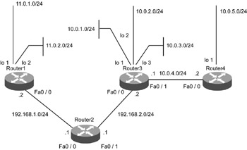
Figure 6.8: Scenario to describe the time required to build a consistent routing table across four routers.
In the topology shown in Figure 6.8, assume that the router link from Router1 to Router4 has just been activated. Therefore, none of the routers have any information about the network topology to which they are connected or the next hop router to which they should forward the traffic. The only information they possess at this point is about the directly connected networks.
Table 6.5 shows the details of routing calculation for the RIP routing protocol.
| Situation | Router | Routes | Metric |
|---|---|---|---|
| Before any update, just after the router startup | Router1 | 11.0.1.0 -> Directly connected | |
| 11.0.2.0 -> Directly connected | |||
| 192.168.1.0->Directly connected | |||
| Router2 | 192.168.1.0->Directly connected | ||
| 192.168.2.0->Directly connected | |||
| Router3 | 192.168.2.0->Directly connected | ||
| 10.0.1.0 -> Directly connected | |||
| 10.0.2.0 -> Directly connected | |||
| 10.0.3.0 -> Directly connected | |||
| 10.0.4.0 -> Directly connected | |||
| Router4 | 10.0.4.0 -> Directly connected | ||
| 10.0.5.0 -> Directly connected | |||
| Just after receiving the first update | Router1 | 11.0.2.0 -> Directly connected | |
| 11.0.2.0 -> Directly connected | |||
| 192.168.1.0->Directly connected | 1 | ||
| 192.168.2.0 -> via 192.168.1.1 | |||
| Router2 | 192.168.1.0->Directly connected | ||
| 192.168.2.0->Directly connected | 1 | ||
| 11.0.0.0 -> via 192.168.1.2 | 1 | ||
| 10.0.0.0 -> via 192.168.2.2 | |||
| 192.168.2.0->Directly connected | |||
| 10.0.1.0 -> Directly connected | |||
| 10.0.2.0 -> Directly connected | |||
| Router3 | 10.0.3.0 -> Directly connected | ||
| 10.0.4.0 -> Directly connected | |||
| 192.168.1.0 ->via 192.168.2.1 | 1 | ||
| 10.0.5.0 -> via 10.0.4.2 | 1 | ||
| 10.0.4.0 -> Directly connected | |||
| 10.0.5.0 -> Directly connected | |||
| Router4 | 192.168.2.0 -> via 10.0.4.1 | 1 | |
| 10.0.1.0 -> via 10.0.4.1 | 1 | ||
| 10.0.2.0 -> via 10.0.4.1 | 1 | ||
| 10.0.3.0 -> via 10.0.4.1 | 1 | ||
| Just after receiving the second update | Router1 | 11.0.1.0 -> Directly connected | |
| 11.0.2.0 -> Directly connected | |||
| 192.168.1.0->Directly connected | |||
| 192.168.2.0 -> via 192.168.1.1 | 1 | ||
| 10.0.0.0 -> via 192.168.1.1 | 2 | ||
| Router2 | 192.168.1.0->Directly connected | ||
| 192.168.2.0->Directly connected | |||
| 11.0.0.0 -> via 192.168.1.2 | 1 | ||
| 10.0.0.0 -> via 192.168.2.2 | 1 | ||
| 192.168.2.0->Directly connected | |||
| 10.0.1.0 -> Directly connected | |||
| 10.0.2.0 -> Directly connected | |||
| Router3 | 10.0.3.0 -> Directly connected | ||
| 10.0.4.0 -> Directly connected | |||
| 192.168.1.0 ->via 192.168.2.1 | 1 | ||
| 10.0.5.0 -> via 10.0.4.2 | 1 | ||
| 11.0.0.0 -> via 192.168.2.1 | 2 | ||
| Router4 | 10.0.4.0 -> Directly connected | ||
| 10.0.5.0 -> Directly connected | |||
| 192.168.2.0 -> via 10.0.4.1 | 1 | ||
| 10.0.1.0 -> via 10.0.4.1 | 1 | ||
| 10.0.2.0 -> via 10.0.4.1 | 1 | ||
| 10.0.3.0 -> via 10.0.4.1 | 1 | ||
| Just after receiving the third update | Router1 | 11.0.1.0 -> Directly connected | |
| 11.0.2.0 -> Directly connected | |||
| 192.168.1.0->Directly connected | |||
| 192.168.2.0 -> via 192.168.1.1 | 1 | ||
| 10.0.0.0 -> via 192.168.1.1 | 2 | ||
| Router2 | 192.168.1.0->Directly connected | ||
| 192.168.2.0->Directly connected | |||
| 11.0.0.0 -> via 192.168.1.2 | 1 | ||
| 10.0.0.0 -> via 192.168.2.2 | 1 | ||
| Router3 | 192.168.2.0->Directly connected | ||
| 10.0.1.0 -> Directly connected | |||
| 10.0.2.0 -> Directly connected | |||
| 10.0.3.0 -> Directly connected | |||
| 10.0.4.0 -> Directly connected | |||
| 192.168.1.0 ->via 192.168.2.1 | 1 | ||
| 10.0.5.0 -> via 10.0.4.2 | 1 | ||
| 11.0.0.0 -> via 192.168.2.1 | 2 | ||
| Router4 | 10.0.4.0 -> Directly connected | ||
| 10.0.5.0 -> Directly connected | |||
| 192.168.2.0 -> via 10.0.4.1 | 1 | ||
| 10.0.1.0 -> via 10.0.4.1 | 1 | ||
| 10.0.2.0 -> via 10.0.4.1 | 1 | ||
| 10.0.3.0 -> via 10.0.4.1 | 1 | ||
| 11.0.0.0 -> via 10.0.4.1 | 3 |
-
Hop count
-
Split horizon
-
Route poisoning
-
Triggered updates
-
Hold-down timers
Hop Count
Also referred to as counting to infinity, hop count sets the maximum number of routers that a particular path can cross. This parameter helps control the endless routing loops in the network. According to this control, the maximum number of hop counts a path can cross is 15, and a hop count of 16 and onwards is called an invalid path or an unreachable path.
Split Horizon
According to the distance vector functionalities, every router sends its entire routing table information as an update to the directly connected neighbors. The split horizon deviates from this routine activity by restricting the routers from sending information about the network interface from which it was learned. The route entry pointing back to the router from which that particular route was learned is known as the reverse route, which becomes the major cause for maturing of routing loops. The split horizon eliminates the existence of reverse routes and helps in avoiding routing loops. There are two types of split horizon methods:
-
Simple split horizon
-
Split horizon with poisoned reverse
-
Simple Split Horizon
This is defined as sending updates out of an interface, excluding the networks that were learned from the updates received on that interface. For example, as per Figure 6.8, when Router3 sends its routing update to Router4 via its interface fa0/0, the information sent will be as shown in Table 6.6.
Table 6.6: Routing Update Information for Router3 Routes
Metric
Status
192.168.2.0 -> Directly connected
Will be sent
10.0.1.0 -> Directly connected
Will be sent
10.0.2.0 -> Directly connected
Will be sent
10.0.3.0 -> Directly connected
Will be sent
10.0.4.0 -> Directly connected
1
Will not be sent
192.168.1.0 ->via 192.168.2.1
1
Will be sent
10.0.5.0 -> via 10.0.4.2
2
Will not be sent
11.0.0.0 -> via 192.168.2.1
Will be sent
The update packet broadcasted from Router4 on its interface fa0/0 will not carry any information about the networks learned from Router3. This is shown in Table 6.7.
| Routes | Metric | Status |
|---|---|---|
| 10.0.4.0 -> Directly connected | Will not be sent | |
| 10.0.5.0 -> Directly connected | Will be sent | |
| 192.168.2.0 -> via 10.0.4.1 | 1 | Will not be sent |
| 10.0.1.0 -> via 10.0.4.1 | 1 | Will not be sent |
| 10.0.2.0 -> via 10.0.4.1 | 1 | Will not be sent |
| 10.0.3.0 -> via 10.0.4.1 | 1 | Will not be sent |
| 11.0.0.0 -> via 10.0.4.1 | 3 | Will not be sent |
To check the split horizon configuration status for an interface, look at the highlighted line in the output of the command show ip interface fa0/0 from Router4, as shown in Listing 6.52.
Listing 6.52 Output of show ip interface fa0/0 Command from Router4
Router4#show ip interface fa0/0 FastEthernet0/0 is up, line protocol is up Internet address is 10.4.0.2/16 Broadcast address is 255.255.0.0 MTU 1500 bytes, Helper address is not set Directed broadcast forwarding is disabled Outgoing access list is not set Inbound access list is not set Proxy ARP Is Enabled Security Level Is Default Split horizon Is Enabled ICMP redirects are always sent ICMP unreachables are always sent ICMP mask replies are never sent IP fast switching is enabled IP fast switching on the same interface is enabled IP Null turbo vector IP multicast fast switching is enabled IP multicast distributed fast switching is disabled router Discovery Is disabled IP output packet accounting is disabled IP access violation accounting is disabled TCP/IP header compression is disabled RTP/IP header compression is disabled Probe proxy name replies are disabled Policy routing Is disabled Network address translation is disabled WCCP Redirect outbound is disabled WCCP Redirect exclude is disabled BGP Policy Mapping is disabled
To enable and disable the split horizon, use the command shown in Listing 6.53 from the interface configuration mode.
Listing 6.53 Command to Enable and Disable Split Horizon
Router#conf t Router(config)#int fa0/0 Router(config-if)#ip split-horizon = Enables Router(config-if)#no ip split-horizon = Disables
EAN: 2147483647
Pages: 130