Case Study
Figure 12.6 depicts a complex routing scenario, which has a combination of both static routing and dynamic routing protocols, including RIP and EIGRP. The places where different routing protocols have been used are marked in the figure.
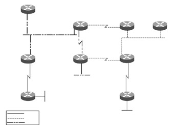
Figure 12.6: A complex routing scenario running RIP and EIGRP.
In Figure 12.6, routers B1 and B2 are exclusively running EIGRP, and routers B6 and B7 are exclusively running RIP. Static routing is configured between routers
B2 and B3, and the static routes are redistributed to EIGRP in router B2. Static routing is also configured between routers B8 and B9, and these routes are being redistributed into RIP at router B8. Redistribution from RIP to EIGRP is configured at router B4, and that from EIGRP to RIP is configured in router B5. Table 12.6 lists configuration of all nine routers B1, B2, B3, B4, B5, B6, B7, B8, and B9.
| Router | Relevant Part of Configuration |
|---|---|
| B1 | interface Ethernet0 |
| ip address 192.168.30.1 255.255.255.0 | |
| ! | |
| router eigrp 100 | |
| network 192.168.30.0 | |
| ! | |
| B2 | interface Ethernet1 |
| ip address 192.168.30.3 255.255.255.0 | |
| ! | |
| interface Serial0 | |
| ip address 10.10.1.1 255.255.255.252 | |
| ! | |
| router eigrp 100 | |
| network 192.168.30.0 | |
| network 10.10.1.0 | |
| redistribute static metric 10000 100 250 3 1500 | |
| ! | |
| B3 | ip route 172.16.10.0 255.255.255.128 10.10.1.2 |
| interface Ethernet0 | |
| ip address 172.16.10.1 255.255.255.128 | |
| ! | |
| interface Serial1 | |
| ip address 10.10.1.2 255.255.255.252 | |
| ! | |
| ip route 0.0.0.0 0.0.0.0 10.10.1.1 | |
| B4 | interface Ethernet1 |
| ip address 192.168.30.2 255.255.255.0 | |
| ! | |
| interface Serial0 | |
| ip address 10.10.2.1 255.255.255.252 | |
| ! | |
| interface Serial2 | |
| ip address 10.10.3.1 255.255.255.252 | |
| ! | |
| router eigrp 100 | |
| network 192.168.30.0 | |
| network 10.10.2.0 | |
| network 10.10.3.0 | |
| redistribute rip metric 10000 100 250 | |
| passive-interface Serial2 | |
| ! | |
| router rip | |
| network 192.168.30.0 | |
| network 10.10.2.0 | |
| network 10.10.3.0 | |
| passive-interface Serial0 | |
| passive-interface Ethernet1 | |
| ! | |
| B5 | interface Ethernet0 |
| ip address 192.168.10.1 255.255.255.0 | |
| ! | |
| interface Serial1 | |
| ip address 10.10.2.2 255.255.255.252 | |
| ! | |
| interface Serial2 | |
| ip address 10.10.4.1 255.255.255.252 | |
| ! | |
| router eigrp 100 | |
| network 192.168.10.0 | |
| network 10.10.2.0 | |
| network 10.10.4.0 | |
| passive-interface Serial2 | |
| ! | |
| router rip | |
| network 192.168.10.0 | |
| network 10.10.2.0 | |
| network 10.10.4.0 | |
| passive-interface Serial1 | |
| passive-interface Ethernet0 | |
| redistribute eigrp 100 metric 1 | |
| ! | |
| B6 | interface Ethernet0 |
| ip address 192.168.20.2 255.255.255.0 | |
| ! | |
| interface Serial1 | |
| ip address 10.10.3.2 255.255.255.252 | |
| ! | |
| router rip | |
| network 192.168.20.0 | |
| network 10.10.3.0 | |
| ! | |
| B7 | interface Ethernet0 |
| ip address 192.168.20.1 255.255.255.0 | |
| ! | |
| router rip | |
| network 192.168.20.0 | |
| ! | |
| B8 | interface Ethernet0 |
| ip address 192.168.20.3 255.255.255.0 | |
| ! | |
| interface Serial1 | |
| ip address 10.10.5.1 255.255.255.252 | |
| ! | |
| interface Serial2 | |
| ip address 10.10.4.2 255.255.255.252 | |
| ! | |
| router rip | |
| network 192.168.20.0 | |
| network 10.10.5.0 | |
| network 10.10.4.0 | |
| redistribute static metric 1 | |
| ! | |
| ip route 172.16.1.0 255.255.255.0 10.10.5.2 | |
| ! | |
| B9 | interface Ethernet0 |
| ip address 172.16.1.0 255.255.255.0 | |
| ! | |
| interface Serial1 | |
| ip address 10.10.5.2 255.255.255.252 | |
| ! | |
| ip route 0.0.0.0 0.0.0.0 10.10.5.1 |
In Figure 12.6:
-
The path from network 192.168.10.0/24 to network 172.16.1.0/24 via B4 is nonoptimal.
-
There is no route of network 172.16.10.0/25 from the RIP routing domain.
Nonoptimal Path from Network 192.168.10.0/24 to Network 172.16.1.0/24
To isolate and resolve this problem:
-
Redistribute static route to 172.16.1.0/24 into RIP at B8, which in turn is redistributed into EIGRP at B4. B5 learns route 172.16.1.0/24 via both EIGRP from B4 and RIP from B8. The EIGRP route is preferred, because it has a lower administrative distance of 90 as compared to 120 of RIP. This results in a nonoptimal route taken from network 192.168.10.0/24 to reach 172.16.1.0/24. The route taken via EIGRP is B5-B4-B6-B8-B9. The optimal route would be via RIP, which is B5-B8-B9.
-
Implement necessary filters to allow for selection of an optimal RIP route to send EIGRP updates from B4 to B5. The relevant part of the configuration of Router B4 is shown in Listing 12.19.
Listing 12.19 Configuration for Optimal RIP Route Selection

router eigrp 100 network 192.168.30.0 network 10.10.2.0 network 10.10.3.0 redistribute rip metric 10000 100 250 3 1500 passive-interface Serial2 distribute-list 2 out Serial0 ! access-list 2 deny 172.16.1.0 0.0.0.255 access-list 2 permit any
The additional configuration commands are shown in bold.
-
Ensure optimal routing since there will be only a single RIP learned route available from network 192.168.10.0/24 to 172.16.1.0/24.
-
Ensure reachability in case of failures by providing a backup path by modifying the administrative distance. The relevant part of the configuration of B5 is shown in Listing 12.20.
Listing 12.20 Part of the Backup Path Configuration
router eigrp 100 network 192.168.10.0 network 10.10.2.0 network 10.10.4.0 passive-interface Serial2 distance 130 0.0.0.0 255.255.255.255 10 ! access-list 10 permit 172.16.1.0 0.0.0.255
In Listing 12.20, some commands have been added, shown in bold. The administrative distance for route 172.16.1.0/24, learned from any EIGRP source, is set at 130, which is higher than that of an RIP route. As a result, by default, the RIP route will be selected, but in case of unavailability of the RIP route, the EIGRP route would be available for routing in the routing table.
Route Unavailable for Network 172.16.10.0/25 from RIP
To isolate and resolve this problem:
-
Redistribute static route to 172.16.10.0/24 into EIGRP at B2, which in turn, is redistributed into RIP at B5.
-
Check for the presence of the EIGRP route in B5. The command to check this is shown in Listing 12.21.
Listing 12.21 Output of the show ip route 172.16.10.1 Command
B5#show ip route 172.16.10.1 Routing entry for 172.16.10.0/25 Known via "eigrp 300", distance 90, metric 41075200, type internal Redistributing via eigrp 300 Last update from 10.10.2.1 on Serial0, 01:01:05 ago Routing Descriptor Blocks: 10.10.2.1, from 192.168.30.3, 01:01:05 ago, via Serial0 Route metric is 41075200, traffic share count is 1 Total delay is 42000 microseconds, minimum bandwidth is 64 Kbit Reliability 255/255, minimum MTU 1500 bytes Loading 3/255, Hops 3
-
Check for the presence of any outbound filter or route map at B4 for any restriction related to network 172.16.1.0/25. This is checked by using the show running-config command. None is found.
-
Check for the presence of any RIP subnetwork of the major network 172.16.0.0/16 in the routing table of B5. You’ll find that a RIP route exists for network 172.16.10/24. Because RIP is a classful routing protocol, it does not understand VLSM and understands only one subnet mask per major network.
-
Propagate any routing information related to network 172.16.0.0/16 in the /24 netmask to resolve this problem. Use this configuration at B2 to achieve this. Use IP route 172.16.1.0 255.255.255.0 10.10.1.2 instead of IP route 172.16.1.0 255.255.255.128 10.10.1.2.
Now, the /24 network will be redistributed into EIGRP at B2 and from EIGRP to RIP at B5, instead of the /25 network. This network with the same netmask as 172.16.10/24 would be advertised in the RIP domain after redistribution and would be reachable from the RIP domain.
EAN: 2147483647
Pages: 130