Dissection of an Actual Probe Response
| Rather than discuss the structure of the Probe Response MMPDU hypothetically, we will examine an actual Probe Response MMPDU, which happens to be 86 octets long, and was captured with the outstanding "Ethereal" protocol analyzer (Ethereal[2] is the product of an open-source programming project). While dissecting this MMPDU, we will also have an excellent opportunity to explore the concepts of "little-endian" versus "big-endian" bit and octet ordering.
Figure 5-5 shows an actual MMPDU that we will examine. The fields alternate in boldface or plain text to make it easier to follow along with the description to follow (referencing the order of the fields in the Probe Response MMPDU header, as depicted in Figure 5-4, then continuing into the Probe Response payload, which we will decode shortly). Figure 5-5. An actual Probe Response MMPDU
The column of numbers on the left side of Figure 5-5 is the octet number (in hexadecimal), so the first row contains the first 16 octets, numbered 0x00 through 0x0F, and the second row contains the next 16 octets (0x10 through 0x1F), and so on. Ethereal has written these octets in "big-endian" notation.[3]
Figure 5-6 illustrates in the case of the two-octet FC field how one converts from the FC field structure that is defined in IEEE 802.11-1999 to what is seen in Ethereal. In this figure, and other similar figures to follow, the graphical packet structure will always be on top, with the bit numbering in place to reinforce the correct relative bit order (in the order specified in the standard). Figure 5-6. The FC field of the Probe Response MMPDU of Figure 5-5
Regardless of whether it is written on the left or right, bit-0 is always the least-significant bit. In figures that have example binary data, that data will appear immediately below the graphic, and the bits will be summarized into nybbles in the next line down. Finally, in the lowest line of the figure, the octets will be written in Ethereal's "big-endian" notation, which reverses the order of the nybbles (i.e., 0x9A in little-endian notation would be written as 0xA9 in big-endian notation). In Figure 5-6, we see the structure of the two-octet FC field, including the bit ordering, which indicated little-endian notation since the highest-numbered bit of the two-octet field is on the right. The bits in this field are numbered 0 through 15, with the least-significant bit (numbered 0) on the left. The IEEE LMSC tends to use this notation little-endian notation in its standards. (The IEEE LMSC is not perfectly consistent, there are exceptions to this rule, but it is a fairly accurate statement.) The IETF tends to write numbers in the opposite way; their so-called "network order" is big-endian, which can cause confusion for people who need to work both sides of the Data Link/Network layer fence. There is no right or wrong way to write binary numbers, but for consistency (and to help minimize confusion) on must choose to either put the least-significant bit on the right or the left and to stick with one's decision. Besides being written on the left in the IEEE LMSC's standards, the least-significant bit of the least-significant octet is usually the first bit to be transmitted onto the medium. One thing to keep in mind about the hexadecimal representation of the frame is that the frame arrives one octet at a time, so Ethereal does not know that the first two octets are one field. The order in which the octets are displayed is the order in which they arrived from the physical medium. If one was writing the entire FC field in little-endian notation, it would cover all 16 bits, and would be written as 0x0050. Yet, since the 0x50 was the first octet off the "wire," and the 0x00 was the second, we actually see the first two octets of the hexadecimal representation of the frame as 0x5000. The first (i.e., leftmost) octet consists of the following bit pattern: "00001010", which would be interpreted as 0x0A if this field were interpreted as having been written using big-endian notation, but big-endian notation is not being used in this case. In little-endian notation, we must interpret the bits within the octet in the reverse order, as if they were written as "01010000", which is 0x50 in its hexadecimal representation. There is no conflict between these notations, since it is still the case that in the binary representation of 0x50, the least-significant nybble[4] is 0x0, and the least-significant bit is part of the "Protocol Version" number. As shown in Figure 5-6, the first (least-significant) nybble is 0x0, and the next-most-significant nybble is 0x5 (when the bits are interpreted in little-endian notation). We combine those two nybbles into 0x50, in which the "5" is written first.
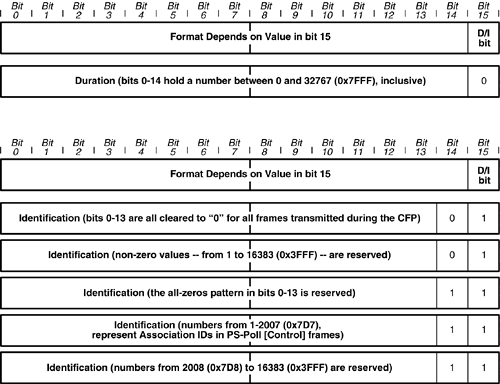
If we look back at Table 4-1, we see that when the "Type" field within the FC field is set to 00, we have an MMPDU (i.e., an MMPDU). Moreover, when the Subtype is set to "0101," we have a Probe Response MMPDU. Note that the bit patterns in Table 4-1 are listed in "big-endian" format for convenience of comparing them to the packet decodes you might encounter in the real world. We will now work our way through the actual captured packet in Figure 5-5, taking advantage of the fact that alternate fields have been set in boldface type. After the two-octet FC field (value: 0x5000), we have the "Duration" subfield, which is also a two-octet field (whose format is shown in Figure 5-7). Figure 5-7. The Duration subfield of Figure 5-5's Probe Response MMPDU
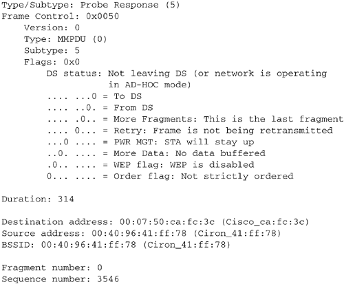
The contents in this case are "0x3A01" (the value from Figure 5-5 has been illustrated here in Figure 5-7). We can use our knowledge of little- and big-endian number formats to interpret this field. First, we reverse the order of the hexadecimal digits (nybbles) to yield "0x013A". This hexadecimal number is equivalent to the decimal number 314, which is what Ethereal computed in the packet decode (see Figure 5-10). Figure 5-10. Ethereal decode of the MMPDU header
The meaning of the D/I field (in an MMPDU, it is always a "D" field; in fact, the only time it is interpreted as an "I" field is when it contains an Association ID, which is the case in a PS-Poll Control frame) depends on the most-significant bit. Figure 5-8 shows how bits 15 (and 14) of the D/I subfield control the interpretation of the values in this subfield. The bits in the case of this frame indicate a Duration interpretation, which is what would be expected of any MMPDU. Figure 5-8. Interpretation of the Duration/Identification subfield
The first row in Figure 5-8 is the overall structure of the D/I subfield. If the most significant bit (bit-15) is 0, this two-octet subfield is interpreted as a "Duration" field (this is always the case for MMPDUs); otherwise, this subfield is interpreted as an "Identification" field. When the D/I subfield is a Duration subfield, the 15 bits that are less significant than the D/I bit hold a little-endian encoded value from 0 to 32,767 (0x7FFF). There are basically two sub-cases when the D/I field is set to "1", which correspond to bit-14 being set to 0 or 1.
The next subfield in Figure 5-5 is the MAC-DA. This field contains the MAC address of the STA that sent the Probe Request that generated this Probe Response. The value in this field (translated to big-endian notation) is 0x000750cafc3c. The subsequent two subfields are the MAC-SA and the BSSID, in that order. In this case, the two fields contain the same value, viz. 0x00409641ff78. In this case, the AP that transmitted the Probe Response frame was also the AP that defined its own MAC address to be this BSS's BSSID, which is why these two fields contain the same MAC address. Since there is typically one AP per BSS, this will be the typical situation for packets sourced by the AP. In general, however, these two fields could contain different values, such as when the AP is forwarding a packet from one node to another; for example, a multicast Data frame. The MAC-SA in that case will be the original sender's MAC address, but the AP will tag the frame with its own BSSID so that receiving STAs (that may be in range of multiple APs) can filter which multicasts they receive based on the BSSID of the BSS that the STA has actually joined. After the BSSID is the final subfield in the MMPDU header, namely the Sequence Control (SC) subfield. Figure 5-9 shows the format of the SC subfield, which encodes two values, the Fragment Number and the Sequence Number. Figure 5-9. The Sequence Control subfield in the MMPDU header
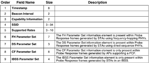
The values below the diagram in Figure 5-9 show the values from the packet capture in Figure 5-5, which was 0xA0DD. Breaking that down and reversing it into little-endian representation, we see that the Fragment Number field is set to 0x0 (it is just a single nybble), and the Sequence Number field contains 0xDDA, which is 3546 in decimal notation, and this number agrees with the Ethereal packet decode shown in Figure 5-10. Since the More Fragments bit in the FC field of the MMPDU header is clear, this is not fragment number zero of a series of MMPDUs that are fragments of a larger MMPDU (both Management and Data frames are eligible for fragmentation; Control frames are too short to need that service). To put the previous discussion in perspective, Figure 5-10 illustrates the complete Ethereal decode of the MMPDU header, which is the first 24 octets of any MMPDU. The Probe Response frame body may contain a number of Information Elements (IEs). This particular complete MMPDU is a total of 86 octets in length. Figure 5-11 shows the ordering of these IEs, along with a brief description of each. The figure also shows the length (or range of possible lengths) for each IE. Figure 5-11. Ordering of the Probe Response MMPDU's Payload fields
The first three fields (Timestamp, Beacon Interval, and Capability Information) are each a fixed length, and total 12 octets in all. The subsequent fields are all TLV-encoded, and if they are not necessary, they are omitted. The first field in the data portion of the MMPDU frame is the Timestamp field, which is simply an eight-octet, little-endian-encoded, numerical value. Its purpose is to help keep the entire membership of STAs in a given BSS running on the same clock. The Timestamp field is expressed in units of microseconds (abbreviated µs; the abbreviation "us" is frequently used when the Greek letter "mu" (µ) is not available). The Timestamp field is also used to keep all the STAs in the BSS aware of the latest BSS parameters. If a Beacon or Probe Response is received that has parameters that differ from those that the STA has on record, it will adopt the new values only if the Timestamp field is newer than the Timestamp that was associated with the most recent Beacon or Probe Response data of which the STA has a record. In the case of the packet we have been examining from Figure 5-5, the contents of the Timestamp field are 0x4a5336f200000000. To make it easier to read this long hexadecimal number, each successive octet is either underlined (or not) so that each octet is easily identified. As one would expect, the Timestamp field, like any other counter, is incremented by adding to the least-significant portion of the value. Consistent with little-endian notation, the value is stored in the leftmost portion of the Timestamp field. If we examine only the portion of the field that has been set (i.e., the least-significant four octets), we can interpret the value in this field. Figure 5-12 breaks out these four octets into their little-endian representation. Figure 5-12. The Timestamp field of Figure 5-5
After converting this four-octet binary number to its decimal equivalent, we obtain a value of 4,063,646,538 µs, or a value just slightly less than 4,064 seconds.[6] The IEEE 802.11 MAC header's usage of the Timestamp field allows the STAs to remain in synchronization with the AP to within 4 µs, plus the maximum delay involved in propagating a frame across the BSS (provided the speeds being used in the BSS are at least 1 Mbps).
The next subfield in the Probe Response MMPDU's payload is the Beacon Interval subfield. It is a simple two-octet numerical field. The number indicates the desired time interval between the Target Beacon Transmission Times (TBTTs). If the medium is busy when the AP becomes ready to transmit a Beacon, it will allow the existing communication to finish before transmitting its Beacon. Thus, the interval between Beacon frames will not be less than the Beacon Interval, but it is possible for the interval between Beacons to exceed the value specified in the Beacon Interval field. The units for the Beacon Interval field are kilo-microseconds (1,024 µs). In the IEEE 802.11-1999 specification, the term "Time Unit" is introduced, and defined such that one Time Unit is equal to 1 kµs (i.e., one Time Unit is equal to 1.024 ms). Figure 5-13 shows the Beacon Interval field from the packet capture in Figure 5-5. Figure 5-13. The Beacon Interval field of the MMPDU in Figure 5-5
In the case of the Beacon Interval field from the MMPDU frame in Figure 5-5, we see that the Beacon Interval is 64 Time Units, or 64x1024 µs, which is the same as 65,536 µs, or 65.536 ms (milliseconds…the conventional kind, i.e., exactly 10-3 seconds, or 1/1000th of a second). In order to express the Beacon Interval without any confusing notation, the value in this example works out to 0.065536 seconds. Following the Beacon Interval field is the Capability Information field. This field tells the STAs some of the configuration choices the network manager has made. The Capability Information field, along with the values from the packet in Figure 5-5, is shown in Figure 5-14. Figure 5-14. The Probe Response Capability Information field
Since there are only two BSS modes, namely "infrastructure" or "independent" BSS, it is strange that the IEEE 802.11 MAC protocol designers chose to give each choice its own control bit. If the ESS bit is set, the transmitter is basically declaring itself to be an AP. When operating in IBSS mode, a STA sets the IBSS bit in its Beacon[7] or Probe Responses. In the case of the MMPDU from Figure 5-5, the ESS bit (Bit 0) is set, and the IBSS bit (Bit 1) is clear.[8]
Bits 2 and 3 are used to control aspects of the Point Coordination Function (PCF) mode of medium access control. As a preview of PCF, suffice it to say that in PCF mode, a central control entity known as the "Point Coordinator" (in the AP) acts to collect frames from WLAN STAs by polling each STA, rather than by allowing each STA with data to send to independently contend for access to the medium. The "CF" abbreviation in each of the labels for Bits 2 and 3 means "Contention-Free," as distinguished from the access method that is based on contention. Bit 4 is labeled "Priv." and is more completely known as the "Privacy" bit. This bit is used to indicate that the sender of the Probe Response packet supports data privacy protocols, if desired. Bit 5 in the Capability Information field has been defined to indicate whether an AP supports the "Short Preamble" format at the PLCP layer. You will recall this concept from Chapter 3, Speeds and Feeds. In IEEE 802.11b, the Short Preamble was not mandatory-to-implement, and in order for a STA to use it, the STA needed to know whether the AP could receive a frame that was sent using a different preamble than was defined in IEEE 802.11-1999. Bit 6 indicates that the AP can support frames encoded using Packet Binary Convolutional Coding (PBCC). PBCC support is defined in IEEE 802.11b-1999 as an optional modulation technique. PBCC modulation only affects the 5.5 Mbps and 11 Mbps speeds that were added by IEEE 802.11b-1999. The default modulation technique for the two "High Rate" speeds (i.e., 5.5 and 11 Mbps) is known as Complementary Code Keying (CCK). Bit 7 indicates that the sender of the Probe Response MMPDU supports "Channel Agility." This capability is used to indicate that a STA can support both FH and DS mode PHYs at the same time. Such a capability would be useful to an AP, but a STA in IBSS mode would also perhaps find this useful. When the Channel Agility bit in the Capability Information field is set, we should expect to see both a DS Parameter Set and an FH Parameter Set (see Figure 5-11). Devices with PHYs that only support Frequency Hopping or Direct Sequence (DS) Spread Spectrum will clear this bit and only transmit the IE that defines their local configuration. The next bits were defined in IEEE 802.11g-2003. Bit 10 is defined in IEEE 802.11g to indicate support for the optional Short Slot Time capability. Bit 13 is defined to indicate support for the optional modulation scheme known as CCK-OFDM. The bits in the remainder of the Capability Information subfield are undefined at the time of this writing, and should be considered reserved for future use. All the remaining IEs are "Type-Length-Value" encoded. For now, suffice it to say that by "TLV-encoded," we mean that each field is self-describing, since it starts with a one-octet Type field, followed by a one-octet Length field, and finally a field containing the Value that is being conveyed in a given IE. The value in the Length octet does not include either the one-octet Type or Length fields themselves (i.e., the Length expresses the amount of data that is carried within the TLV, not the length of the entire TLV, which is two octets larger). Despite the interpretation of the "L" in TLV (as being the length of the "V" portion of the TLV), the "Size" column in Figure 5-11 reflects the entire TLV field, so that a direct comparison of field sizes can be made by remembering that TLV-encoded fields are actually two octets larger than the value in the table). Following the fixed-length Capability Information subfield is the first TLV-encoded IE in the Probe Response MMPDU's payload. This subfield is used to transmit the SSID of the ESS in which the AP is operating. The SSID is a string of up to 32 ASCII characters that uniquely identifies the BSS. End users will encounter the SSID in their WLAN driver configuration utilities when they have to enter the name of the WLAN to which they are attaching their STA. Modern operating systems such as Microsoft's Windows XP can learn the SSID from the Probe Response or Beacon MMPDUs, which eliminates the need for the user to manually enter this information, and to enter it without making any typographical errors. In the case of the example MMPDU of Figure 5-5, the SSID IE is interpreted in Figure 5-15. The first octet contains the "T" of the TLV, in this case 0x00, which agrees with the value in the table shown in Figure 5-11. The second octet, the "L" of the TLV, contains the value 0x07, meaning that the SSID is stored in the next seven octets. Figure 5-15. The TLV-Encoded SSID IE
In this case, the SSID string contained in the SSID IE is the ASCII string "tsunami" (the ASCII codes are all lowercase letters in this example). This TLV is nine octets long, overall, with seven octets of actual data. By observing that T=0x00 a receiver can properly interpret the octets in the Value field, since these octets are ASCII text in the SSID IE. The SSID field can be up to 32 octets in length, so the L field is from 1 to 32 (there is no good reason to send a null SSID in a Beacon or Probe Response; in a Probe Request, a null SSID corresponds to the "broadcast" or "wildcard" SSID, which is a mechanism that a STA can use to find out what SSIDs it may be near). After the SSID IE, comes the TLV defined in Figure 5-16. Based on Figure 5-11, we can expect this next TLV to be the Supported Rates TLV. Since any implementation knows that this is a TLV (we have already seen all the fixed-length entries in this example), it can look at the second octet after the "i" in the SSID IE (i.e., the last letter of "tsunami") to see how long this next TLV is, since that's where the next TLV's length field would be. Even if this subsequent TLV isn't one that the implementation can decode, the implementation can at least skip over this TLV and hope to find a subsequent TLV that it can understand. Figure 5-16. Decoding the Supported Rates IE
By definition (per IEEE 802.11-1999 and IEEE 802.11b-1999), the Supported Rates IE can have up to a total of eight octets of payload; however, in this example only four octets are actually used. The Supported Rates IE must list at least one Supported Rate. Thus, this IE will always be at least three octets in length, but no more than 10 octets long. In the latter case, at its maximum size, this IE would list eight Supported Rates, each encoded in a single octet (expressed in units of 500 kbps). Thus, this mechanism may only express speeds from 500 kbps to 255 x 500 kbps (i.e., 127.5 Mbps).[9]
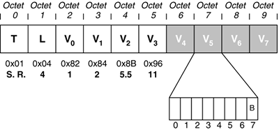
The Supported Rates is only used in the Beacon, Probe Response, and the Association and Reassociation Response MMPDUs. There are two types of rates, namely those in the "Basic Rate Set" and those that are not in the Basic Rate Set. The Basic Rate Set is the set of rates (known as "basic rates") that the AP expects all the STAs in the BSS to be able to support. If a STA does not support all the basic rates advertised by an AP, it can choose to not associate with that AP. This decision on the part of the STA is not a requirement…STAs may still choose to associate in such circumstances, but while the standard never comes out and says it, this practice is not recommended. The "B" bit is only significant in the four MMPDUs mentioned previously. When this IE is present in any type of MMPDU, the value of the "B" bit is ignored, although encoding the rate using more than seven bits is never allowed. Figure 5-17 shows the format of the Supported Rates IE, including the specific values from our example MMPDU, and includes a layout of each octet of the IE. A value of 0x02 equates to 1 Mbps, a value of 0x04 equates to 2 Mbps, a value of 11 (0x0B) equates to 5.5 Mbps, and a value of 22 (0x16) equates to 11 Mbps. Figure 5-17. Supported Rates IE
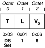
You will note that the values in the Value octets are not the same as those in the preceding sentence. When used, the "B" bit is interpreted as follows: The "B" bit is set to "1" when a rate is in the Basic Rate Set. Otherwise, it is clear for other non-Basic rates. The fact that each of the octets from the example MMPDU has the most-significant bit set indicates that these rates are part of the Basic Rate Set. The values in that case, for 1, 2, 5.5, and 11 Mbps, respectively, are 0x82, 0x84, 0x8B, and 0x96. There are only two fields left in the payload of the example MMPDU in Figure 5-5. First, we have the DS Parameter Set, shown in Figure 5-18. The fact that this is the DS Parameter Set is indicated by the fact that the Type octet contains 0x03. The Length field indicates a single octet in the Value portion, which is set to 6, meaning that this AP is using Channel 6 on which it is operating in DS Spread Spectrum DSSS mode. Figure 5-18. The DS Parameter Set IE
The final field is depicted in Figure 5-19, and is proprietary to the vendor, so there is no way that we can decode the meaning of the final 32 octets of the MMPDU. Figure 5-19. A Proprietary TLV IE
The T-number for this IE is 0x85 (decimal 133), which is currently a reserved value and thus has no publicly defined meaning. The one thing we can decode is that the L field of the TLV is set to 0x1E (decimal 30), which does match the length of the mystery "V" field, so at least we can be confident that we have a complete IE, even though we do not know what it means. If a STA encounters an IE that it does not understand, it can ignore that IE, and use the value in the L portion of the TLV to skip over the unknown TLV to the start of the next IE. |
EAN: 2147483647
Pages: 60
- ERP Systems Impact on Organizations
- ERP System Acquisition: A Process Model and Results From an Austrian Survey
- Data Mining for Business Process Reengineering
- Relevance and Micro-Relevance for the Professional as Determinants of IT-Diffusion and IT-Use in Healthcare
- Development of Interactive Web Sites to Enhance Police/Community Relations


