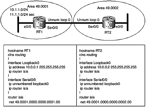
Configuring IS-IS Capabilities
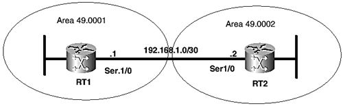
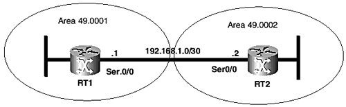
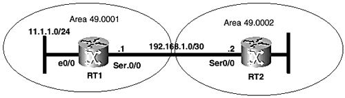
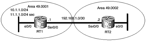
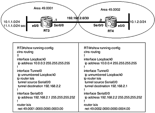
| The Cisco implementation of IS-IS provides numerous configuration options for enabling various IS-IS capabilities and modifying protocol parameters both globally and on a per-interface basis. This section presents some of these configuration options, such as advertising default routes, route summarization, and enabling authentication. Route leaking and IS-IS multi-area support are features recently introduced into the Cisco IS-IS implementation. The essence of these features and basic configurations are discussed briefly . For a current and more complete list of IS-IS configuration options available in the Cisco IOS Software, see the Cisco Configuration Guide at www.cisco.com. Advertising the IP Default Route in IS-ISIn the original protocol design of IS-IS, Level 1 areas are stubs and Level 1-only routers automatically install a default route to the nearest Level 1-2 router in the area. Level 1-2 routers set the ATT bit in the Level 1 LSPs they advertise into their native areas. TheATT-bit setting in LSPs provide a clue to Level 1-only routers about Level 2-capable routers in the area. The Level 2 routers connected to the IS-IS backbone are expected to know about all routes in the IS-IS domain and do not set any automatic defaults. To advertise a default route into the IS-IS backbone requires the router-level default-information originate command. When configured on a router, the command inserts the IP prefix 0.0.0.0/0 as the default route into its Level 2 LSP targeted at the other Level 2 routers in the domain. The default is advertised into the backbone, whether the router has prior or no knowledge of a default route from another source. Example 9-6, which is based on Figure 9-9, shows the configuration and application of the default-information originate command. Notice the default entry in the output of the show isis database command in Example 9-6. Figure 9-9. Diagram for Example 9-6. Example 9-6 The default-information originate CommandRT1# show running-config [snip] Hostname RT1 ! router isis default-information originate net 49.0001.0000.0000.0001.00 [snip] RT2# show isis database detail RT1.00-00 IS-IS Level-2 LSP RT1.00-00 LSPID LSP Seq Num LSP Checksum LSP Holdtime ATT/P/OL RT1.00-00 0x000000E1 0x7A1E 651 0/0/0 Area Address: 49.0001 NLPID: 0xCC Hostname: RT1 IP Address: 10.1.1.1 Metric: 10 IS RT1.01 Metric: 10 IS RT2.00 Metric: 0 IP 0.0.0.0 0.0.0.0 Metric: 10 IP 10.1.1.1 255.255.255.255 Metric: 10 IP 192.168.1.0 255.255.255.252 RedistributionCisco IOS Software allows IP routes from other routing sources to be imported into IS-IS. Examples of the external sources are static routes, the Routing Information Protocol (RIP), and the Open Shortest Path First Protocol (OSPF). The IP external reachability TLV is used for adding external routes into the IS-IS domain. Even though RFC 1195 specifies the IP external reachability for only Level 2 LSPs, Cisco IOS Software provides a special capability for using them in Level 1 LSPs, which allows external routes into a Level 1 area. Most service provider networks use IS-IS as the IGP in large single-area Level 1-only or Level 2-only domains. For those with Level 1-only backbones, the capability to redistribute into Level 1 provides flexibility to import external routes into the IS-IS domain. Even though this behavior is not standardized, it should not pose interoperability issues with other vendor routers because both existing IS-IS standards, ISO 10589 and RFC 1195, require IS-IS implementations to ignore unsupported or unknown optional TLVs encountered while parsing IS-IS packets. The IOS router-level command redistribute enables redistribution. This command takes on other options, such as metric value, metric type, route map, and so on. In the Cisco implementation of IS-IS, CLNS static routes are automatically distributed into IS-IS. However, IP static routes are redistributed only by manual configuration. When static IP routes need to be redistributed, the redistribute command requires the keyword ip to go with it, in addition to the other arguments previously mentioned. The metric type for external routes can be either internal or external. Internal metrics are comparable to metrics used for internal routes. External metrics require the I/E bit (bit 7) of the metric field to be set in addition to the actual metric, resulting in higher metric values. In current Cisco IOS Software releases, when using narrow metrics, bit 8 of the default metric field is set for external metrics, resulting in an increase of the metric value by 128. By default, the internal metric type is assigned if nothing is specified in the configuration. Also, the external routes are added into Level 2 unless Level 1 is explicitly stated in the configuration. Figure 9-10 illustrates basic examples of redistribution in IS-IS. In Example 9-7, only the ip keyword is used with the redistribute command. Figure 9-10. Network topology for IS-IS route redistribution examples. Example 9-7 Configuring Basic Route Redistribution in IS-ISRT1# conf t Enter configuration commands, one per line. End with CNTL/Z. RT1(config)#router isis RT1(config-router)#redistribute static ip RT1(config-router)#^Z RT1# show running-config [snip] router isis redistribute static ip metric 0 metric-type internal level-2 net 49.0001.0000.0000.0001.00 ! ip route 172.16.1.0 255.255.255.0 Null0 [snip] The following output from RT1 (see Example 9-8) displays the contents of its own Level 1 and Level 2 LSPs. In Example 9-7, note that internal metric type has been assigned by default and the metric applied is 0. Example 9-8 shows that the external static route has been added to only the Level 2 LSP. Example 9-8 LSP Contents in Case of Simple RedistributionRT1# show isis database RT1.00-00 detail IS-IS Level-1 LSP RT1.00-00 LSPID LSP Seq Num LSP Checksum LSP Holdtime ATT/P/OL RT1.00-00 * 0x00000DB0 0xEB25 979 1/0/0 Area Address: 49.0001 NLPID: 0xCC Hostname: RT1 IP Address: 10.0.0.1 Metric: 10 IP 10.1.1.0 255.255.255.0 Metric: 10 IP 10.0.0.1 255.255.255.255 Metric: 10 IP 192.168.1.0 255.255.255.252 Metric: 10 IS RT1.02 Metric: 10 IS RT1.01 Metric: 0 ES RT1 IS-IS Level-2 LSP RT1.00-00 LSPID LSP Seq Num LSP Checksum LSP Holdtime ATT/P/OL RT1.00-00 * 0x00000E3D 0x6F45 977 0/0/0 Area Address: 49.0001 NLPID: 0xCC Hostname: RT1 IP Address: 10.0.0.1 Metric: 10 IS RT1.02 Metric: 10 IS RT1.01 Metric: 10 IS RT2.00 Metric: 0 IP-External 172.16.1.0 255.255.255. 0 Metric: 10 IP 10.1.1.0 255.255.255.0 Metric: 10 IP 10.0.0.1 255.255.255.255 Metric: 10 IP 192.168.1.0 255.255.255.252 In Example 9-9, the metric type is explicitly set to external in the configuration, but no metric value is applied. As explained previously, the I/E bit needs to then be set for the external metric type, effectively increasing the metric value by 64. However, Cisco IOS Software sets bit 8 of the narrow metric instead of bit 7, consequently adding 128 instead to the original value of 0. The Level 2 LSP displayed in Example 9-9 shows 128 as the metric value for the external route, 172.16.1.0/24. Example 9-9 Configuring Redistribution with External MetricsRT1# conf t Enter configuration commands, one per line. End with CNTL/Z. RT1(config)#router isis RT1(config-router)#redistribute static ip metric-type external RT1(config-router)#^Z RT1# show running-config [snip] router isis redistribute static ip metric 0 metric-type external level-2 net 49.0001.0000.0000.0001.00 ! ip route 172.16.1.0 255.255.255.0 null 0 [snip] RT1# show isis database level-2 RT1.00-00 detail IS-IS Level-2 LSP RT1.00-00 LSPID LSP Seq Num LSP Checksum LSP Holdtime ATT/P/OL RT1.00-00 * 0x00000E44 0x7FAD 703 0/0/0 Area Address: 49.0001 NLPID: 0xCC Hostname: RT1 IP Address: 10.0.0.1 Metric: 10 IS RT1.02 Metric: 10 IS RT1.01 Metric: 10 IS RT2.00 Metric: 128 IP-External 172.16.1.0 255.255.255. 0 Metric: 10 IP 10.1.1.0 255.255.255.0 Metric: 10 IP 10.0.0.1 255.255.255.255 Metric: 10 IP 192.168.1.0 255.255.255.252 The IP routing table output from RT2 shows the external route, 172.16.1.0/24, which was redistributed from a static source into IS-IS on router RT1 (see Example 9-10). The metric entered for this route, 138, is the total of the metric on the outgoing interface from RT2to RT1 (10) plus the metric of 128 advertised by RT1. Other routes received from RT1 (10.0.0.1/32 and 10.1.1.0/24) are registered with a metric of 20 (10 advertised by RT1 and additional 10 for the metric from RT2 to RT1). Example 9-10 Representation of External IS-IS Routes in the IP Routing TableRT2# show ip route 172.16.0.0/24 is subnetted, 2 subnets i L2 172.16.1.0 [115/138] via 192.168.1.1, Serial0/ 0 10.0.0.0/8 is variably subnetted, 4 subnets, 2 masks C 10.0.0.2/32 is directly connected, Loopback0 i L2 10.1.1.0/24 [115/20] via 192.168.1.1, Serial0/0 C 10.2.2.0/24 is directly connected, Ethernet0/0 i L2 10.0.0.1/32 [115/20] via 192.168.1.1, Serial0/0 192.168.1.0/30 is subnetted, 1 subnets C 192.168.1.0 is directly connected, Serial0/0 The route-map option of the redistribute command provides more flexibility for configuring redistribution, such as selective importation of external routes into the IS-IS environment, applying special tags, and even setting the metric of redistributed routes. When used for selective importation of routes into IS-IS, route maps provide a filtering effect by controlling which elements from an external source are allowed or denied into IS-IS. Examples 9-11a and 9-11b show redistribution with route maps. In the first example, static routes are redistributed into IS-IS while filtering through the route map TEST. Route map TEST matches the static routes against access list 1, which permits only 172.16.2.0/24 into the IS-IS environment. RT1's LSP is shown from RT2. Also shown is the routing table of RT2. In Example 9-11b, the route map approach is used to set the metric for routes imported into IS-IS. Example 9-11a Using Route Maps to Filter External RoutesRT1# show running-config ! router isis redistribute static ip metric 0 route-map TEST metric-type external level-2 net 49.0001.0000.0000.0001.00 ! ip route 172.16.1.0 255.255.255.0 Null0 ip route 172.16.2.0 255.255.255.0 Null0 ! access-list 1 permit 172.16.2.0 ! route-map TEST permit 10 match ip address 1 RT2# show isis database level-2 RT1.00-00 detail IS-IS Level-2 LSP RT1.00-00 LSPID LSP Seq Num LSP Checksum LSP Holdtime ATT/P/OL RT1.00-00 0x00000E62 0x8588 1026 0/0/0 Area Address: 49.0001 NLPID: 0xCC Hostname: RT1 IP Address: 10.0.0.1 Metric: 10 IS RT1.02 Metric: 10 IS RT1.01 Metric: 10 IS RT2.00 Metric: 128 IP-External 172.16.2.0 255.255.255.0 Metric: 10 IP 10.1.1.0 255.255.255.0 Metric: 10 IP 10.0.0.1 255.255.255.255 Metric: 10 IP 192.168.1.0 255.255.255.252 RT2# show ip route 172.16.0.0/24 is subnetted, 1 subnets i L2 172.16.2.0 [115/138] via 192.168.1.1, Serial0/0 10.0.0.0/8 is variably subnetted, 4 subnets, 2 masks C 10.0.0.2/32 is directly connected, Loopback0 i L2 10.1.1.0/24 [115/20] via 192.168.1.1, Serial0/0 C 10.2.2.0/24 is directly connected, Ethernet0/0 i L2 10.0.0.1/32 [115/20] via 192.168.1.1, Serial0/0 192.168.1.0/30 is subnetted, 1 subnets C 192.168.1.0 is directly connected, Serial0/0 Example 9-11b Setting the Metric with a Route MapRT1# show running-config ! router isis redistribute static ip route-map SETMETRIC net 49.0001.0000.0000.0001.00 is-type level-1 metric-style wide ! route-map SETMETRIC permit 10 set metric 1000 set level level-1 RT1# show isis database detail RT1.00-00 level-1 IS-IS Level-1 LSP RT1.00-00 LSPID LSP Seq Num LSP Checksum LSP Holdtime ATT/P/OL RT1.00-00 * 0x00000E56 0x0A4C 1128 0/0/0 Area Address: 49 NLPID: 0xCC Hostname: RT1 IP Address: 10.0.0.1 Metric: 10 IS-Extended RT1.02 Metric: 10 IS-Extended RT1.01 Metric: 10 IS-Extended RT2.00 Metric: 1000 IP 10.1.1.0 255.255.255.0 Metric: 1000 IP 10.0.0.1 255.255.255.255 Metric: 1000 IP 192.168.1.0 255.255.255.252 IP Route SummarizationAn IS-IS router can be configured to summarize IP routes into Level 1, Level 2, or both, at the same time, with the following router-level configuration command: summary-address <prefix> [level-1level-2level-1-2]. By default, summaries go into Level 2 if no routing level option is indicated. An illustration of how summarization is configured and its operation is provided by the series of outputs shown in Example 9-13, which is based on Figure 9-11. The set of outputs in Example 9-12 depict the scenario where summarization is not configured yet on RT1, which has three interfaces: loopback 0, Ethernet0/0, and Serial0/0. Example 9-12 shows the LSP for RT1 as captured on RT2 and the routing table on RT2. The route of interest, 11.1.1.0/24, is not summarized here; however, it is summarized in Example 9-13 into 11.1.0.0/16. Figure 9-11. Network diagram for summarization example. Example 9-12 IS-IS Configuration Without SummarizationRT1 #show running-config interface loopback 0 ip address 10.0.0.1 255.255.255.255 ip router isis ! interface Ethernet0/0 ip address 11.1.1.1 255.255.255.0 ip router isis ! interface Serial0/0 ip address 192.168.1.1 255.255.255.252 ip router isis router isis net 49.0001.0000.0000.0001.00 RT2 #show isis database level-2 RT1.00-00 IS-IS Level-2 LSP RT1.00-00 LSPID LSP Seq Num LSP Checksum LSP Holdtime ATT/P/OL RT1.00-00 0x00000E62 0x8588 1026 0/0/0 Area Address: 49.0001 NLPID: 0xCC Hostname: RT1 IP Address: 10.0.0.1 Metric: 10 IS RT1.02 Metric: 10 IS RT1.01 Metric: 10 IS RT2.00 Metric: 10 IP 11.1.1.0 255.255.255.0 Metric: 10 IP 10.0.0.1 255.255.255.255 Metric: 10 IP 192.168.1.0 255.255.255.252 RT2 #show ip route 10.0.0.0/8 is variably subnetted, 3 subnets, 2 masks C 10.0.0.2/32 is directly connected, Loopback0 C 10.2.2.0/24 is directly connected, Ethernet0/0 i L2 10.0.0.1/32 [115/20] via 192.168.1.1, Serial0/0 11.0.0.0/24 is subnetted, 1 subnets i L2 11.1.1.0 [115/20] via 192.168.1.1, Serial0/0 192.168.1.0/30 is subnetted, 1 subnets C 192.168.1.0 is directly connected, Serial0/0 Example 9-13 IS-IS Configuration with SummarizationRT1# show running-config ! router isis summary-address 11.1.0.0 255.255.0.0 net 49.0001.0000.0000.0001.00 RT2# show isis dat l2 RT1.00-00 det IS-IS Level-2 LSP RT1.00-00 LSPID LSP Seq Num LSP Checksum LSP Holdtime ATT/P/OL RT1.00-00 0x00000E68 0x0D4A 1193 0/0/0 Area Address: 49.0001 NLPID: 0xCC Hostname: RT1 IP Address: 10.0.0.1 Metric: 10 IS RT1.02 Metric: 10 IS RT1.01 Metric: 10 IS RT2.00 Metric: 10 IP 10.0.0.1 255.255.255.255 Metric: 10 IP 11.1.0.0 255.255.0.0 Metric: 10 IP 192.168.1.0 255.255.255.252 RT2# show ip route 10.0.0.0/8 is variably subnetted, 3 subnets, 2 masks C 10.0.0.2/32 is directly connected, Loopback0 C 10.2.2.0/24 is directly connected, Ethernet0/0 i L2 10.0.0.1/32 [115/20] via 192.168.1.1, Serial0/0 11.0.0.0/16 is subnetted, 1 subnets i L2 11.1.0.0 [115/20] via 192.168.1.1, Serial0/0 192.168.1.0/30 is subnetted, 1 subnets C 192.168.1.0 is directly connected, Serial0/0 Secondary Addresses, Unnumbered Interfaces, and Tunneling ConfigurationsThis section discusses IS-IS configuration on routers with secondary IP subnets, IP unnumbered interfaces, and IP tunnel interfaces. The outputs in Examples 9-13, 9-14, and 9-15 feature the respective configurations and LSPs of the routers involved. Configuring IS-IS on Routers with Secondary IP SubnetsNo special configuration is required to advertise secondary IP subnets from IS-IS-enabled interfaces by the IS-IS process. Note that the IS-IS configuration does not require IP network statements, and IP subnets on interfaces where IS-IS routing is enabled are automatically added to LSPs by way of IP internal reachability or extended IP reachability TLVs. Example 9-14, which is based on Figure 9-12, shows the configuration of RT1 with a secondary IP subnet. Also shown is the corresponding LSP of RT1. Figure 9-12. Network diagram for Example 9-14. Example 9-14 Secondary IP Subnet ConfigurationRT1 (config-if)# ip address 11.1.1.1 255.255.255.0 secondary RT1 (config-if)#^Z RT1# show running-config [snip] Interface Ethernet0/0 Ip address 11.1.1.1 255.255.255.0 secondary Ip address 10.1.1.1 255.255.255.0 ! Interface Serial0/0 Ip address 192.168.1.1 255.255.255.252 No ip directed-broadcast Ip router Isis ! Router Isis Net 49.0001.0000.0000.0001.00 ! [snip] RT1 #show Isis database level-1 RT1.00-00 detail IS-IS Level-1 LSP RT1.00-00 LSPID LSP Esq. Num LSP Checksum LSP Hold time ATT/P/OL RT1.00-00 * 0x00000033 0x3CBB 1125 1/0/0 Area Address: 49.0001 NLPID: 0xCC Hostname: RT1 IP Address: 10.0.0.1 Metric: 10 IP 10.1.1.0 255.255.255.0 Metric: 10 IP 11.1.1.0 255.255.255.0 Metric: 10 IP 192.168.1.0 255.255.255.252 Metric: 10 IP 10.0.0.1 255.255.255.255 Metric: 10 IS RT1.02 Metric: 10 IS RT1.01 Metric: 0 ES RT1 Configuring IS-IS on Routers with Unnumbered LinksIP unnumbered interfaces can be used with IS-IS without any problems. When connected interfaces are numbered, Cisco IOS Software requires that IP addresses on interfaces connected to the same link belong to the same subnet for the IS-IS adjacency to work. However, this requirement does not apply when using unnumbered interfaces on point-to-point links, either in serial or NBMA. Both sides of the point-to-point link need to be configured as unnumbered interfaces for the adjacency to be established. Figure 9-13 shows IS-IS enabled on unnumbered interfaces. Figure 9-13. IP unnumbered configuration. Example 9-15 shows the routing table on RT1 and RT2. Notice that each router shows the borrowed address: at the other router as the next hop of learned routes. Example 9-15 The IP Routing Table in an Unnumbered EnvironmentRT1# show ip route 10.0.0.0/8 is variably subnetted, 3 subnets, 2 masks I L2 10.0.0.2/32 [115/20] via 10.0.0.2, Serial0/0 C 10.1.1.0/24 is directly connected, Ethernet0/0 C 10.0.0.1/32 is directly connected, Loopback0 11.0.0.0/24 is subnetted, 1 subnets C 11.1.1.0 is directly connected, Ethernet0/0 RT2# show ip route 10.0.0.0/8 is variably subnetted, 4 subnets, 2 masks C 10.0.0.2/32 is directly connected, Loopback0 i L2 10.1.1.0/24 [115/20] via 10.0.0.1, Serial0/0 C 10.2.2.0/24 is directly connected, Ethernet0/0 i L2 10.0.0.1/32 [115/20] via 10.0.0.1, Serial0/0 11.0.0.0/24 is subnetted, 1 subnets i L2 11.1.1.0 [115/20] via 10.0.0.1, Serial0/0 IS-IS over IP TunnelsFigure 9-14 shows the configuration of IS-IS routing over an IP tunnel. The example is simplistic because in a real scenario, the tunnel would span over a cloud of non-IS-IS routers to connect two IS-IS network segments. In this scenario, IS-IS connectivity is between RT3 and RT4 only over the IP tunnel. This configuration has no relevance to virtual links, which are not supported in current Cisco IOS releases. The show clns neighbors outputs in Example 9-16 confirm that the adjacency is formed over the tunnel. The routing tables of RT4 show IS-IS routes are being learned over the tunnel. Figure 9-14. IS-IS over IP tunnel configuration. Example 9-16 IP IS-IS over Tunnel ConfigurationRT3# show clns neighbors System Id Interface SNPA State Holdtime Type Protocol RT4 Tu0 192.168.2.2 Up 27 L2 IS-IS RT4# show clns neighbors System Id Interface SNPA State Holdtime Type Protocol RT3 Tu0 192.168.2.1 Up 25 L2 IS-IS RT4# show ip route 10.0.0.0/8 is variably subnetted, 3 subnets, 2 masks C 10.1.2.0/24 is directly connected, Ethernet0/0 i L2 10.1.1.0/24 [115/20] via 10.0.0.3, Tunnel0 C 10.0.0.4/32 is directly connected, Loopback0 11.0.0.0/24 is subnetted, 1 subnets i L2 11.1.1.0 [115/30] via 10.0.0.3, Tunnel0 192.168.2.0/30 is subnetted, 1 subnets C 192.168.2.0 is directly connected, Serial0/0 AuthenticationISO 10589 and RFC 1195 specify only simple plain-text passwords for authentication of IS-IS packets. A more recent RFC draft (IS-IS HMAC-MD5 Authentication, draft-ietf-isis-hmac-00.txt) proposes a mechanism for using the HMAC-MD5 authentication algorithm to provide a more sophisticated authentication scheme for IS-IS. Current Cisco IOS Software supports only the simple text-based passwords. As mentioned in Chapter 3, "Integrated IS-IS Routing Protocol Concepts," IS-IS packets are not encapsulated in Layer 3 packets (IP or CLNP) as is the case of other IP routing protocols. Encapsulation over Layer 2 provides IS-IS some security advantages, in that the IS-IS process cannot be inundated by IP attacks from remote. It would require physical access to the IS-IS network to attempt an attack on the IS-IS processes running on the routers. This is certainly considered a security advantage. Clear-text IS-IS authentication can be configured in the following three ways:
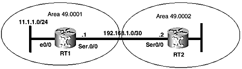
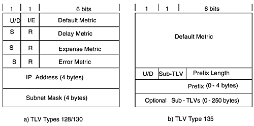
Example 9-17, which is based on Figure 9-15, shows a configuration example and illustrates the operation of per-interface or link authentication in IS-IS. In example 9-16, a password is configured on only one side of the serial link, on RT1. Observe how the adjacency is affected, as shown in the show clns neighbor output. Figure 9-15. Network diagram for Examples 9-16 and 9-17. Example 9-17 Enabling IS-IS Authentication on an InterfaceRT1# configure terminal Enter configuration commands, one per line. End with CNTL/Z. RT1(config)#int s0/0 RT1(config-if)#isis password cisco level-2 RT1(config-if)#^Z RT1# show clns neighbor System Id Interface SNPA State Holdtime Type Protocol RT2 Se0/0 *HDLC* Up 278 IS ES-IS RT2# show clns neighbor System Id Interface SNPA State Holdtime Type Protocol RT1 Se0/0 *HDLC* Init 21 L2 IS-IS The outputs of the show clns neighbor command display the adjacency status on both routers after the password is configured on only RT1, with no matching password on router RT2. This information indicates that RT1 completely ignores the IIHs of RT2 because they could not be authenticated. RT1, however, still discovers ES-IS adjacency with RT2 by means of ISHs exchanged between them. On the other hand, RT2 is not configured for authentication, so it accepts and processes the IIHs from RT1 and then moves the status of the adjacency to Init. The adjacency remains in Init state because RT2 never receives an IIH from RT1 recognizing RT2 as an IS neighbor, to complete the three-way adjacency formation process. The following output of debug isis adj-packets on RT1 demonstrates the authentication process between RT1 and RT2 (see Example 9-18). Configuring a password on RT2 to match the password on RT1 results in successful authentication and subsequent completion of the three-way handshake process. Example 9-18 Debugging Authentication FailuresRT1# debug isis adj-packets *Apr 23 04:25:36: ISIS-Adj: Rec serial IIH from *HDLC* (Serial0/0), cir type L1L2, cir id 00, length 1499 *Apr 23 04:25:36: ISIS-Adj: Authentication failed *Apr 23 04:25:42: ISIS-Adj: Sending serial IIH on Serial0/0, length 1499 *Apr 23 04:25:46: ISIS-Adj: Rec serial IIH from *HDLC* (Serial0/0), cir type L1L2, cir id 00, length 1499 *Apr 23 04:25:46: ISIS-Adj: Authentication failed *Apr 23 04:25:50: ISIS-Adj: Sending serial IIH on Serial0/0, length 1499 . RT2# conf t Enter configuration commands, one per line. End with CNTL/Z. RT2(config)#int s0/0 RT2(config-if)#isis password cisco RT2(config-if)#^Z RT2# show clns neighbor System Id Interface SNPA State Holdtime Type Protocol RT1 Se0/0 *HDLC* Up 21 L2 IS-IS Domain-Wide Prefix Distribution (L2 to L1 Route Leaking)RFC 2966 specifies a mechanism for domain-wide prefix distribution in an IS-IS network, effectively removing the stub-only capability specified by ISO 10589 for Level 1 areas. This feature is available in current Cisco IOS Software and it is known as IS-IS route leaking. The objective of route leaking is to enable interarea routes to be leaked into IS-IS Level 1 areas so that Level 1 routers have more information to make optimal interarea routing decisions. Without distributing interarea routes into Level 1, IS-IS areas function as stubs, and Level 1 routers forward traffic to destinations in other areas through the nearest Level 1-2 router. The Cisco IOS configuration for route leaking uses the router-level redistribute command with a newly defined option. No special TLVs are required to advertise interarea routes from Level 2 into Level 1. The capability just allows Level 2 routes carried in TLVs 128, 130, and 135 to be injected into the various Level 1 areas in the domain. RFC 2966 specifies a procedure to prevent route feedback, which ensures that routes advertised into Level 1 from Level 2 are not advertised back into Level 2. TLV 135 features a dedicated up/down (U/D) bit (see Figure 9-16), which is set when a route is advertised from Level 2 into Level 1. RFC 2966 proposes using bit 8 in the default metric field of TLV 128 and 130 as the up/down bit to protect against routing loops when route leaking is enabled. Prefixes with the U/D bit set are never propagated from Level 1 to Level 2. Figure 9-16. Up/Down (U/D) bit in IP reachability TLVs. Because Cisco IOS Software sets bit 8 for external metrics when routes for external sources are advertised into IS-IS, using the same bit for route leaking might result in conflicting situations. Also note that only IS-IS routes that are Level 2 routes in the routing table are "leaked" into Level 1. Remember the following when configuring route leaking in Cisco-based IS-IS environments:
The following two different command-line syntaxes are supported in Cisco IOS Software for configuring route leaking. The second variant of the command is deprecated:
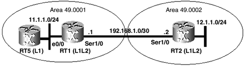
Also, the IP prefixes need to be present in the routing table as the IS-IS Level 2 route for them to be advertised into Level 1. In the example shown in Figure 9-17, RT2 advertises 12.1.1.0/24 to RT1 through Level 2. As depicted in the configuration shown in Example 9-19, RT1 then summarizes 12.1.1.0/24 into 12.0.0.0/8 and then "leaks" it into Level 1. The route is advertised into Level 1 by adding the summary prefix to the locally generated Level 1 LSP and flooding it into area 49.0001. Example 9-19 also shows the Level 1 LSP of RT1 displayed in detail from RT5. Figure 9-17. Diagram for the Level 2 to Level 1 route leaking example. Example 9-19 Route Leaking ExampleRT1# interface Ethernet0/0 ip address 11.1.1.1 255.255.255.0 ip router isis ! interface Serial0/0 ip address 192.168.1.1 255.255.255.252 ip router isis ! router isis summary-address 12.0.0.0 255.0.0.0 level- 1 redistribute isis ip level-2 into level- 1 net 49.0001.0000.0000.0001.00 RT5 #show isis data level-1 detail RT1.00-00 IS-IS Level-1 LSP RT1.00-00 LSPID LSP Seq Num LSP Checksum LSP Holdtime ATT/P/OL RT1.00-00 0x000000F7 0xF8AA 518 1/0/0 Area Address: 49.0001 NLPID: 0xCC Hostname: RT1 IP Address: 10.1.1.1 Metric: 10 IS RT1.02 Metric: 10 IS RT1.01 Metric: 10 IS RT5.00 Metric: 10 IP 10.1.1.1 255.255.255.255 Metric: 10 IP 11.1.1.0 255.255.255.0 Metric: 10 IP 192.168.1.0 255.255.255.252 Metric: 20 IP-Interarea 12.0.0.0 255.0.0.0 Multi-Area ConfigurationPrior to the availability of IS-IS multi-area capability in Cisco IOS releases, each IS-IS router could be in only a single area (even when configured with multiple area IDs for multihoming). As mentioned in Chapter 4, "Addressing in Integrated IS-IS," in multihoming scenarios, the multiple areas configured are effectively merged into a single area; also, only one IS-IS process can be configured per router. Multi-area support allows a single router to participate in up to 29 independent Level 1 areas with one of them doubling as Level 2 if necessary. The feature is designed primarily for telecommunications management networks that use IS-IS for routing. IS-IS multi-area support provides the flexibility to have one router support multiple areas in the management network in a cost-effective manner. In essence, this feature allows up to 29 IS-IS processes to be configured on a single router, one of which can be Level 1-2 and the remainder only Level 1. Note, however, the following restrictions:
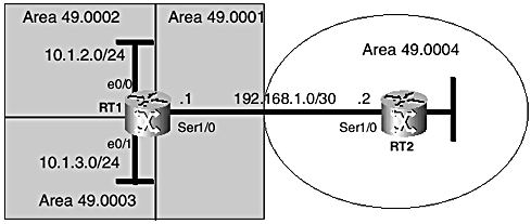
Figure 9-18 shows a multi-area scenario. In the corresponding Cisco IOS configuration output for RT1 shown in Example 9-20, three processes are running, tagged Core (Level 1-2), Access-2 (Level 1), and Access-3 (Level 1). Each process has a different area ID in its NSAP address, but they all share the same system ID (0000.0000.0001). The multi-area functionality is borrowed from the OSPF protocol and presents significant advantages for efficient network design. For more information, see the Introduction and Configuration Guide on IS-IS multi-area support. Figure 9-18. Diagram for the multi-area configuration example. Example 9-20 Multi-Area Configuration ExampleRT1# interface Serial1/0 ip address 192.169.1.1 255.255.255.0 ip router isis Core interface Ethernet0/0 ip address 11.1.2.1 255.255.255.0 ip router isis Access-2 interface Ethernet0/1 ip address 11.1.3.1 255.255.255.0 ip router isis Access-3 router isis CORE net 49.0001.0000.0000.0001.00 ! router isis Access-2 net 49.0002.0000.0000.0001.00 is-type level-1 ! router isis Access-3 net 49.0003.0000.0000.0001.00 is-type level-1 |
EAN: 2147483647
Pages: 144