Using IS-IS as an IGP
Over the past few years , IS-IS has become increasingly more popular for use as an IGP. Previously, IS-IS was more prevalent in government and academic networks, the majority of which were pure CLNS environments that did not carry IP prefix information.
The IS-IS protocol seems to be widely perceived as difficult to understand and to configure. One of probable reasons for this is the additional requirement for CLNP (or NSAP) addresses. The node-based NSAP addresses differ vastly from IP addresses (see Chapter 4, "Addressing in Integrated IS-IS") and require familiarity to work with comfortably. However, the comparable routing protocol, such as the Open Shortest Path First (OSPF) Protocol, works with only IP addresses. Even though OSPF is similar in many regards to IS-IS, differences in the CLNP and IP addressing schemes (node-based versus link-based , respectively) result in OSPF defining its area boundaries on the router itself, whereas IS-IS defines its boundaries on the network links between routers in different areas.
Also, because an NSAP can potentially be up to 20 bytes in length, it adds to the complexity of the protocol. Another reason many people did not adopt the protocol earlier was that there was inadequate information regarding design and configuration guidelines. This is now improving and certainly a major factor in the growing popularity of the protocol.
Many major service providers run IS-IS in some of the largest IP networks in the world. Inherently, the IS-IS protocol tends to be very scalable and can accommodate large areas. Being pure link-state, it can react quickly to changes and thus attain fast convergence. Also, because IS-IS uses TLVs to encode information in all packets, it can be easily extended. IS-IS has many configurable timers that you can tune to enhance its operation, such as reducing convergence time, increasing stability, and controlling flooding ”to name but a few. Although these timers might be more challenging to tune effectively, they make the protocol more flexible, scalable, and robust. This is a definite plus because you can literally tailor the protocol by using the timers to meet your specific network requirements.
One of the reasons that IS-IS is such a flexible and relatively simple protocol is that not many rigid standards exist for it to adhere to ” especially when compared to OSPF. Some might be disappointed about the lack of rigorous standards that cover some the more recently added capabilities, yet other might see it as an advantage.
Protocol Limitations to Consider
Like any IGP, Integrated IS-IS has some limitations. Many of the previous protocol limitations have been removed as a result of recent IETF drafts and RFCs and corresponding enhancements in Cisco IOS Software. The following sections examine these limitations in more detail.
Metric Limitation
Before the introduction of new TLVs that support larger metrics, Integrated IS-IS was limited to a 6-bit interface metric and a 10-bit path metric. This gave a range of 1 to 63 for the interface metric and a value of 1023 for the total path metric. If implementations that do not support the new TLVs are used, the interface and maximum path metric limitation still applies.
Area Limitation
Before the introduction of route leaking, IS-IS areas resembled the model of an OSPF "stub area," with the exception that external information could be redistributed into the Level 1 areas on Cisco routers. As a result, the only way to exit an area was to forward packets to the closest Level 1-2 router, increasing the potential for suboptimal forwarding.
Route leaking eliminated this problem by providing a means to "leak" routes present in the Level 2 database to the Level 1 areas. As a result of this new capability, a Level 1 router can make a much better decision regarding the best point to exit the area to reach the final destination. This is particularly useful for shortest exit routing when coexisting with BGP, and also for optimal reachability to the loopback address of the provider edge (PE) router when using Integrated IS-IS in Multiprotocol Label Switching-based Virtual Private Networks ( MPLS-VPN) applications.
MPLS is a mechanism used to forward packets across a network from an ingress router toward an egress router without the need to analyze network layer destination IP addresses. MPLS assigns labels to packets and utilizes label swapping to forward the packets through the network. Each packet carries a short, fixed-length label that informs switching nodes along the path how to process and forward the data.
Virtual private networks (VPNs) can be defined as networks in which connectivity between multiple customer sites is deployed on a shared infrastructure with the same access or security policies as a private network infrastructure. A detailed description of the concepts and architectures of MPLS-VPN is beyond the scope of this book.
Maximum Number of Advertised IP Prefixes
A major limitation to consider is the maximum number of routes an IS-IS router can support, which is limited to approximately 30,000 routes. This limitation exists because of a maximum of 256 LSP fragments per router, each of which will not take more than 121 IP prefixes. This is essentially a technical limitation of the protocol and should not be considered for practical purposes because in most applications, the IGP does not carry this many routes. The majority of the routes are carried in BGP, which relies on the IGP to help resolve next hop information. Therefore, the IGP tracks subnets assigned to links in the networks, and the order of IGP routes is normally significantly far less than 30,000.
A recently published IETF draft, draft-hermelin-ext-lsp-frags-00.txt, proposes increasing the maximum number of LSP fragments beyond the 256 current limit by using multiple system IDs on the same intermediate system. However, as mentioned previously, a currently deployed network that carries anywhere close to the 30,000 IP prefixes per router in its IGP is open to serious scrutiny. Existing IGPs were never designed to carry this number of routes and might experience operational problems if they are pushed to these limits.
Metrics, Nonhierarchical Design
As previously mentioned, by default, all IS-IS interface metrics are set to 10. Therefore, all the interface metrics might need to be redefined and configured depending on the required traffic flow.
Two main styles of metrics exist: narrow and wide. Narrow metrics are commonly called old-style TLVs and wide metrics are referred to as new-style TLVs. The following sections look at how the metrics are used and assigned.
Using Narrow Metrics
If using older implementations that do not support the new TLV types (which allow interface metric values larger than 63), you must take care when deciding which value to apply to each interface. All interface metrics must be configured manually because autoconfiguration does not exist based on parameters, such as bandwidth, as in OSPF.
Also, with bandwidth capacity of media types increasing to extremely high values, such as OC-192, there is a huge range of bandwidth to fit into the small range of narrow metrics ”especially if there are small bandwidth interfaces to consider in the network.
Metrics are an important consideration when designing any network, and IS-IS is no exception. The interface and path metrics influence the way the traffic flows around the network, and, therefore, you must carefully plan metric assignments to achieve the desired results.
As with most routing protocols, in IS-IS, a lower metric is preferred over a larger value. Therefore, when using narrow metrics, which allows an interface metric range from 1 to 63, 1 is the best and 63 is the worst that can be assigned. If you have no other alternative than to use the old-style TLVs and, therefore, "narrow" metrics, you need to make an informed decision about which metric values to assign to the lowest and highest bandwidth interfaces in the network. When deciding which values to assign, it is prudent to take into consideration additional interfaces of higher bandwidth that might be used in the near future.
There is little benefit to designing a metric scheme that requires major modifications when new interfaces are added. So, plan ahead and be proactive. Investigate which interface speeds might be added in the future and leave room for growth. If future interfaces are known in advance, you can easily accommodate them.
Using Wide Metrics
Wide metrics provide a much larger range for both interface and total path metrics. Wide metrics use 24 bits for interface metrics and 32 bits for path metrics compared to 6 bits and 10 bits, respectively, for narrow metrics. This provides a huge range to design with and effectively removes the limitations associated with narrow metrics.
Some recent applications, such as MPLS traffic engineering, are supported using only wide metrics. Therefore, all routers that are required to run MPLS traffic engineering must support the new-style TLVs (Types 22 and 135).
Again, a structured approach must be taken when deciding on a metric assignment using wide metrics. Although the previous issues have been removed, it would be difficult and time consuming to enter large metric values on each router interface. This calls for a simple and practical metric assignment scheme.
Assigning Metric Values
In the vast majority of cases, you initially need to assign a lower metric value to a higher bandwidth interface to ensure that the traffic is forwarded along the path with the lowest delay. Because a high price tag is associated with high bandwidth interfaces and corresponding circuits, it seems logical to use the large capacity links as much as possible. Also, the less- congested path should be the one that has the least delay ”although this is not always the case.
NOTE
Although bandwidth is the term that is perhaps most commonly used when choosing the best path, the most important factor to consider is delay.
Of course, this might not be applicable to all design scenarios. In a number of valid cases, you might want traffic to follow along the path with the least number of hops, which might not be the same high-bandwidth path (again, seeking the lowest delay, or possibly the highest reliability). Because Integrated IS-IS uses only interface cost as a valid metric, you can rely only on manual configuration to achieve the desired traffic-flow.
When designing traffic flow within and between points of presence using Integrated IS-IS, you might want traffic to flow across the shortest path possible with the least number of hops to reach the destination, instead of taking the route with the highest bandwidth. Consider Figure 7-8, for example, which shows a higher metric assigned to the 155 Mbps interfaces than the other lower bandwidth interfaces. This ensures that the traffic takes the path with the least number of hops to get from source X to destination Y.
Figure 7-8. IS-IS Interface metric assignment.
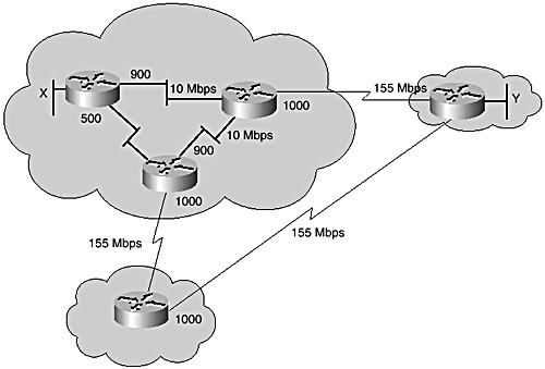
Usually, Internet service providers try to keep the number of hops that traffic traverses in their networks to a minimum. Therefore, in some cases, assigning a lower cost to a lower bandwidth link might be preferred to reduce the hop count, provided there is enough capacity on the path to handle available traffic.
Using Both Narrow and Wide Metrics Together
You can use either narrow or wide metrics when using a nonhierarchical design. The type of metric that can actually be configured depends on the IOS version in use.
NOTE
Cisco IOS Software defaults to narrow metrics. If wide metrics is desired, it must be enabled with the command metric-style wide under router isis. The additional keywords level-1, level-2, or level-1-2 should be appended depending on the mode of operation of the router. All nodes should be configured with the same metric style.
Narrow and wide metrics can coexist. The predominant reason to configure wide metrics, in addition to the existing narrow metrics, is to provide a required transition from one metric style to the other. Routing issues might occur when some nodes use the old-style TLVs and others use the new-style TLVs.
In such circumstances, the information on which the SPF calculation is based might vary significantly from node to node. This can cause routing loops ; and therefore, network administrators need to ensure that all nodes are configured similarly.
Migration from Narrow to Wide Metrics
Cisco IOS Software provides a third metric style command to support transition during metric migration. The command metric-style transition is hidden in IOS.
If a migration from old-style to new-style metrics is required, the easiest and most pain-free method is to introduce a flag day, when availability of network services is completely disrupted while the changes are being implemented. The downside of this is that service interruption might not be acceptable because of operations charter. Another approach to metric migration is to use both the new-style and old-style TLVs together with the metric-style transition command. Doing this, forces each router to advertise and process routes with old and new metric information, which even though implies redundancy, ensures that all routers in the network understand all the advertised information.
One requirement for using this approach is that the configured metric limits for the old-style and new-style TLVs need to be the same. By keeping both values the same, the computation of the SPT is not affected and is consistent across the network.
Beware, however, that this particular method does have some short-term disadvantages, such as the following:
-
All interface metrics are limited to a maximum value of 63.
-
The size of the LSPs increases because more information must be contained within them. Therefore, the originating router might fragment the LSPs more frequently than before, which might lead to some performance issues.
-
There might be some instability experienced during the transition period because of the possibility of increased fragmentation and flooding of more LSPs throughout the network. This might consume additional network bandwidth and also require additional buffering and processing.
NOTE
If different interface metrics are used and an adjacency is advertised more than once by both TLV types, the interface and adjacency with the lowest metric is used.
Because the use of both metric-styles is only recommended in transition, the duration of this period must not be excessive; and therefore, the disadvantages hold true only over the short term. Chapter 8, "Network Design Scenarios," provides practical examples for transitioning between narrow and wide metrics.
Nonhierarchical Design
When designing a nonhierarchical Integrated IS-IS network, you use the same area prefix in the NSAP for all routers in the domain. The area is normally run as a flat Level 1 or Level 2 network. In this scenario, each router maintains a single database, and there is no need for summarization or route leaking within the area. A nonhierarchical design has scaling limitations and ultimately requires some form of redesign into a hierarchical topology if the network is to grow successfully to a large number of nodes.
As discussed previously, the main driver for using a nonhierarchical design in the past was that it helped avoid suboptimal interarea routing in Level-1 areas. This limitation no longer exists in recent IOS software.
A nonhierarchical single area design might potentially have more routers per area than a hierarchical design using a number of areas. This might make the SPF computation more complex and require a longer run time to completion. As discussed previously, only a partial SPF (PRC) needs to be run when changes are external to the area or only IP prefixes are affected by the changes. Instabilities in one part of the network are not masked from other parts within a single area.
The benefits of running a router as both Level 1 and Level 2 within a single area are reduced in a nonhierarchical design. Such a scenario is certainly possible; although in practice, it makes little sense. Consider the design in Figure 7-9. The design has a core of routers running as both Level 1 and Level 2, with leaf routers running as Level 1-only and connected redundantly (dual- homed ) to the core. Assume only Level 2 adjacencies are enabled between the core routers so that they do not exchange Level 1 LSPs ”meaning Level 1 LSPs will not traverse the core between Level 1 routers. Level 1 routers have to depend on default routes to reach remote segments; however, because all routers are in the same area and the core routers are not attached to routers in different areas, they will not set the "attached bit" in their Level 1 LSPs. Therefore, the Level 1-only routers hanging off the core will not set defaults to nearby Level 1-2 routers, making end-to-end reachability impossible . Route leaking could be used to advertise routes from the Level 2 database into Level 1 routers, but there would be little point in doing this because route leaking is meant for advertising interarea routes into Level 1 in a multi-area hierarchical network.
Figure 7-9. Nonhierarchical areas.
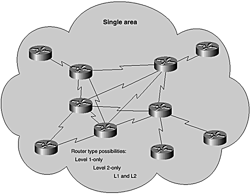
A way around this is to enable Level 1 routing over all routers. However, this defeats the purpose of running Level 2 additionally on the core routers because this transforms the whole domain into a flat Level 1 area with redundant Level 2 routing. If no connections to external areas exist, no interarea routing is required and, therefore, you can make all routers Level 1- or Level 2-only to optimize use of network resources.
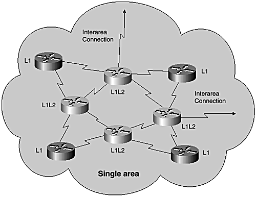
If an area is designed as Level 1-2 and one or more of the core routers are connected to other areas, the attached bit is set in the Level 1 LSPs of Level 1-2 routers, providing an exit point for Level 1 only routers.
In this scenario, you can also selectively leak interarea prefixes Level 2 into Level 1. This avoids the possibility of suboptimal routing and ensures that the Level 1 routers pick the best point for exiting the area. Figure 7-10 shows this type of design.
Figure 7-10. Running an IS as Level 1 to Level 2 in a single area.
A design without hierarchy is certainly much simpler than one with hierarchy. As you have just seen, however, a design can sometimes be a little more challenging when mixing both Level 1 and Level 2 routing.
Interaction with BGP
Integrated IS-IS coexists with BGP, predominantly within Internet service provider networks. Understanding the interaction between IS-IS and BGP is paramount when designing such networks. Sometimes, this interaction can be complex.
Within such environments, Integrated IS-IS, being an Interior Gateway Protocol, is used to carry the BGP next-hop and local routes. This is the main function when using Integrated IS-IS as an IGP in such environments. As discussed later, however, Integrated IS-IS interacts in other ways with BGP.
The next hop addresses associated with BGP routes must be known for the BGP routes to be useful for forwarding traffic. A process within IOS scans the IP routing table to ensure that the next hop of BGP learned prefixes is valid and reachable . If a next hop is found to be invalid or unreachable, an alternate path is selected. Synchronization is a BGP capability that controls how BGP interacts with the IGP. The synchronization feature is enabled by default when running BGP, and its purpose is to ensure that all Internal BGP (iBGP) learned routes are known also within the IGP and, therefore, available at all other routers in the autonomous system before advertising such routes to external destinations. This avoids traffic black-holing, where traffic is attracted from remote ASs, only to be dropped because some router in the path doesn't know how to route to the target address.
The synchronization requirement can be disabled with the "no synchronization" command under the BGP process. In this scenario, routes will be advertised, irrespective of the existence of an IGP route. However, synchronization needs to be turned off only when all transit routers within the AS are running BGP or when the AS is not a transit AS. In Figure 7-11, AS2 is shown as a transit, forwarding traffic between AS1 and AS3.
Figure 7-11. Interaction with BGP: iBGP synchronization.
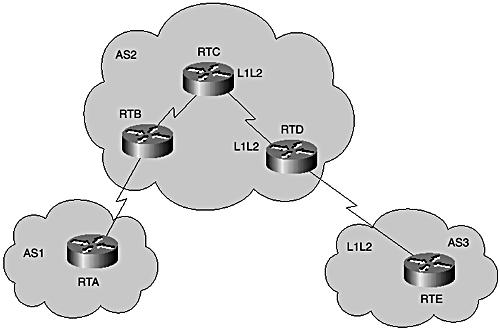
RTA and RTB are external BGP peers (eBGP) and so are RTD and RTE. RTB and RTD are internal BGP peers (iBGP). If RTC in AS2 were to run IS-IS only and not participate in the iBGP with RTB and RTD, you would need to redistribute eBGP routes into IS-IS to ensure that RTC has full information to forward packets between AS1 and AS3. However, redistributing BGP into IGP should be avoided at all costs. One simple reason for this is that there might be more routes carried in BGP than IS-IS can support. You might recall that currently IS-IS is limited to about 30,000 routes, whereas the Internet BGP table is currently (at the time of writing) holding over 100,000 routes.
Synchronization ensures that traffic is not routed between AS1 and AS3 through RTC, which has no knowledge about the external routes exchanged between RTB and RTD through BGP. The best aproach to solve this is to enable BGP peering on RTC. In that case, synchronization can be turned off on all BGP routers in AS2.
Use of the Overload Bit with BGP
Another situation where Integrated IS-IS interacts with BGP is when using a feature of the IS-IS protocol to avoid black-holing traffic at initial power-on or during reload of a router.
Normally, the router sets the overload-bit in its LSP to warn all other routers of an overload condition that would make it potentially unreliable as transit. The capability is defined in the original IS-IS specification but was never leveraged in actual implementations. A recently introduced application of the overload bit is for controlling interaction of IS-IS and BGP in potential service- impacting situations.
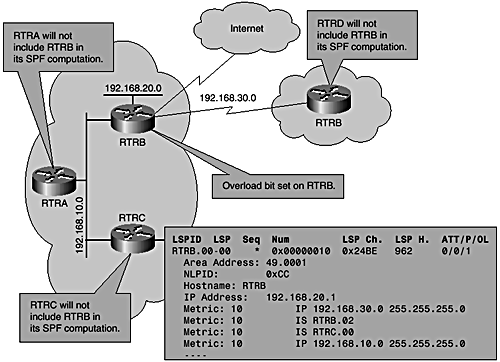
When a router running both Integrated IS-IS and BGP reloads , it might not have had enough time to receive the full BGP table before it starts participating in forwarding traffic, even though it might advertise reachability to IGP next hop of a BGP route. In such a situation, traffic can be dropped if the router is used as transit for destinations it does not yet know. To avoid this situation, you can use a protection mechanism within IS-IS that sets the overload bit in the router's LSP to tell all other routers not to include this particular router when calculating the shortest path tree. The router then waits for a signal from the BGP process after a reasonable interval when all BGP prefixes are expected to have been received. Because BGP has many more prefixes to receive and deal with than an IGP, such as IS-IS, it typically takes much longer to converge. After BGP convergence is flagged, the router can then flood out another LSP with the overload bit turned off. The following command can be used to set the overload bit on start up until BGP signals that it has finished converging:
router isis set-overload-bit on-startup wait-for-bgp
Figure 7-12 illustrates the use of the overload bit. There is a default delay of two minutes (within which BGP is expected to update IS-IS with its state). However, this update delay parameter is configurable under the BGP router process as shown here:
Figure 7-12. Interaction with BGP: overload bit.
router bgp 100 bgp update-delay <sec>
In most current Internet domains, BGP typically converges in less than 5 minutes depending, of course, on a number of factors, such as the number of routes, number of peers, type of routers, bandwidth capacity, and so on. Should it take longer than expected for BGP to converge and the BGP notification is delayed significantly longer than expected, IOS clears the overload bit after 10 minutes.
Another scenario in which the use of the overload bit provides a similar advantage as in the interaction with BGP is when running Integrated IS-IS as the IGP for MPLS networks. During boot up, an MPLS router might not yet have received all labels; therefore, it would be wise not to use this router for a period of time, to allow it to fully receive all labels. In this situation, the IS-IS overload bit can again be set on start up of the router. A typical value in this case would be approximately 2 minutes.
The additional commands that allow the overload bit to interact with BGP are available in recent releases of Cisco IOS Software. The IETF draft draft-mcpherson-isis-transient-00.txt explains and formalizes the use of the overload bit in IS-IS to avoid black-holing traffic.
EAN: 2147483647
Pages: 144