| One of the most difficult body parts to create with NURBS surfaces is a character's head. Among other reasons for this difficulty, the head usually has the most recognizable features and requires that multiple openings be created for the mouth, nose, ears, and eyes. Beginning the modeling process by modeling your character's head with NURBS surfaces will be challenging and will give you a good idea of the strengths and limitations of this surface type. This section introduces you to using NURBS surfaces and shows you how to rough out a specific type of NURBS head from a simple primitive sphere (see Figure 2.2). You are then shown how to manipulate the surface in a variety of ways to create the details of your character's face, with a special focus on understanding edge placement and surface direction. When you understand how to model the NURBS head successfully, you will be able to apply the same modeling principles to the rest of your character's body. 2.2. In this section, you learn how to create a NURBS head from a simple sphere (character model by Shawn Rinehart). 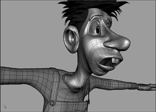
Approaches to Modeling a NURBS Head The two main surface types in Maya are NURBS and polygons. For the purposes of the modeling process described in this chapter, the subdivision surface type is considered an extension of polygons and is mainly used as a way to smooth polygons. A NURBS surface is composed of intersecting curves, whereas a polygon object is composed of a mesh of polygon faces. The difference between NURBS surfaces and polygon objects is similar to the difference between vector images and pixel-based images in 2D drawing programs. NURBS surfaces are like vector images in that they are surfaces interpolated from resolution-independent curves. Polygon objects are similar to pixel-based images in that they are dependent on the number of polygon faces for their resolution. A higher-resolution image requires more pixels, and a higher-resolution polygon object requires more polygons. In a practical sense, this means a NURBS surface can look smoother than a polygon object with the same number of points. You can easily see this by creating a NURBS and polygon sphere with 8-by-8 subdivisions. The polygon sphere has noticeably hard edges, whereas the NURBS sphere appears completely smooth (see Figure 2.3). Increasing the resolution of polygon objects inevitably increases your file size and can make it difficult to adjust anything related to the components, such as deformations when the skin is bound by skeletons. Traditionally, this caused artists to favor NURBS surfaces for characters used in high-resolution mediums, such as films, television, and game cinematics. Although this has changed recently with the advent of subdivision surfaces, which enable you to work with a low-resolution polygon that is automatically smoothed for rendering. 2.3. A NURBS surface (left) is always smoother than a polygon object (right) with the same number of points and subdivisions. 
Many film companies, however, still use NURBS surfaces for creating high-resolution characters, and it behooves any modeler to fully understand how to create a NURBS skin. The first thing to understand about NURBS surfaces is that they are two-dimensional rectangular surfaces created from intersecting curves. In other words, no matter how complex a NURBS surface appears to be, it can always be unwrapped to create nothing more than a rectangle, called a NURBS patch. The two directions of the curves on each NURBS patch are the U and V directions. To see a visual representation of the U and V directions, select any NURBS surface and choose Display, NURBS Components, Surface Origins. This displays the edge curve where the V direction begins as a green line and displays the edge curve where the U direction begins as a red line. Each curve that defines a NURBS surface, called an isoparm, must extend completely across one of these directions. Keep in mind that all NURBS surfaces are continuous, with all isoparms in a particular direction being the same length. You cannot cut a real hole in the middle of a NURBS surface like you can on a polygon object by deleting polygon faces. Using the Trim tool to cut a hole in a NURBS surface, for instance, only creates an optical effect where part of the surface is hidden. For this reason, trims will not be used for openings on a surface that require deformation, such as mouth and eye openings on a head. The isoparms on a NURBS surface allow it to be deformed into a variety of simple shapes. For instance, you can bend a rectangular NURBS patch in the U or V direction until it meets itself. The bent edge can then be closed to create a cylinder (see Figure 2.4). If you bring the other two open ends of the cylinder around to close the other direction on the surface, you get a torus. A NURBS sphere is actually a cylinder whose open poles are pinched together only to appear closed, but are really open. Keep in mind when you are modeling your character that any single NURBS surface can only be deformed into variations of one of these four main shapes: a rectangle, cylinder, sphere, or torus. 2.4. You can deform NURBS surfaces into any shape that can be formed from a rectangle, which includes a cylinder, sphere, and torus. 
Because of the inherent limitations in deforming a rectangle, a single-surface NURBS head is difficult to create. The most basic type of single-surface NURBS head is often called a vertical head, because the basic shape for the head is a vertical cylinder with open poles at the top and bottom (see Figure 2.5). The top pole is pinched to create the top of the head, and the bottom pole is opened to create the neck. Although this type of head is relatively easy to create because the isoparms contour the entire profile of the face, it has some inherent problems when deformed in an animation. The mouth opening is particularly difficult to animate because of the placement of isoparms. To define the sides of the mouth, you must add many horizontal isoparms, which then causes the isoparms to bunch together on the cheeks. This can have an adverse effect when deforming the mouth into a smile, for instance, because the isoparms can start crossing over each other, causing unnatural creasing on the cheeks. 2.5. A vertical NURBS head has the poles at the top of the head and the bottom of the neck. This type of head does not produce good animation results in the mouth area. 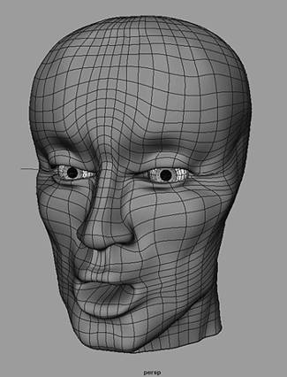
The best type of NURBS surface orientation for creating a deforming mouth is when the open pole of a NURBS cylinder is facing forward. This places one open pole within the mouth, and the other open pole is either on the back of the head or pulled down to create the neck opening. This head type is often called a radial head because the isoparms radiate out from the open mouth across the rest of the face. This orientation enables you to define each part of the mouth opening in the same way, making it easy and predictable to deform. You can run into the same problem as on a vertical head with the eyes, however, by trying to create eye openings from the vertical isoparms on the radial head. If you add isoparms to define the eye sockets, your head will have too many isoparms on the upper lip. To avoid this, you can add the eye openings on the radial head as two separate radial NURBS patches (see Figure 2.6). The edges of each patch must be lined up with the underlying head surface to achieve tangency so that the seam between the surfaces is not very noticeable. You also can place the edge of each eye patch so that it lines up with the socket of the eye to further hide the seam. 2.6. The radial head produces a better mouth structure, but it requires that you create the eye sockets from separate radial patches to avoid adding too many isoparms on the upper lip (character model by Maegan Walling). 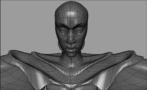
The last type of NURBS head is one created from multiple rectangular patches. This type of head often resembles a patch quilt, in that all the rectangular NURBS patches are lined up to achieve a continuous-looking surface. There are three advantages to creating such a multipatch head. First, you can separate edges if necessary to create openings (see Figure 2.7). Second, you can re-orient isoparms on individual patches in ways that would be impossible on a single NURBS surface. Third, you can often achieve greater surface continuity during animation, because all the edges of the patches line up with each other. Keep in mind that each patch must have the exact same number of isoparms as its neighboring patch to line up perfectly and to create tangency between the patches. 2.7. A multipatch head is like a patch quilt, and has the advantage that seams can be opened (left), or individual patches can be re-oriented while still having the edges line up (right). 
Other methods, such as a radial head with separate radial eye patches, can never achieve perfect surface tangency because the eye patches line up with the middle of the head patch, and the isoparms on the separate surfaces will never line up. This can show up as surface problems when deforming the patches with skeletons. Even though you can create a multipatch head from scratch, it is much easier to first create a radial head with eye patches, and then chop the surfaces into many pieces to line up the edges. In the next section, you begin creating your character's skin by modeling a radial head, which will be converted to a NURBS multipatch head later in this chapter. In the early stages of modeling your character's head, you will import some of your character designs into Maya to use as guides during the modeling process. Roughing Out a Radial NURBS Head One way of beginning a radial head is to create a NURBS sphere so that its poles are pointing forward and backward in the Z-axis. The sphere should be scaled in X and Y to have the basic oval shape of a head. Then in the side view, the first few rows around the front pole of the sphere can be pulled back in Z to form a mouth cavity. To rough out the basic shape of the mouth, it is easiest to use the right mouse button to select and transform hulls rather than individual points. The hulls around the mouth cavity should be scaled and translated downward. You can add isoparms around the mouth to define the shape of the lips, being careful not to add too many at this early stage. Rotate the rows of points around the back pole of the sphere gradually downward until they are horizontal. Then detach the surface around the pole to create an open edge for the base of the neck (see Figure 2.8). 2.8. Begin a radial head by pulling the points around the front pole to create a simple mouth opening (left), and then detach and transform the back pole down to create the neck opening (right). 
At this early stage of modeling your character's head, you want to build the overall shape gradually. Avoid adding too many isoparms in any one area, and try to achieve an even spacing of isoparms on all areas of the surface. Working in the side and front orthographic views, while using clipping planes, manipulate the components of the sphere to shape a basic nose, chin, forehead, and cheekbone. As you continue to shape the head in component mode, notice the points are on the hulls, not on the surface of the NURBS sphere. This can cause the points, otherwise known as control vertices (CVs), to be difficult to manipulate. This can be especially true around areas where the surface is heavily folded, such as on the lips. To more easily move across the component structure of the surface, use the arrow keys. The arrow keys enable you to select the next CV in the U or V direction of the surface, called pickwalking, while manipulating CVs. As you refine the head, keep in mind the eyelids will be added later as separate radial eye patches. To prepare for this, pull the points in the eye area below the brow back to create a slight indention. This gives you a space to place eyeballs and keeps the main head surface from having intersection problems with the overlying eye patches. When roughing your character's basic head shape, it is a common technique to cut it in half to work on only one side of the model. Because the basic structure of a head is symmetrical, detaching and discarding one side of the head along the isoparms that run vertically down the center of the face will simplify the modeling process (see Figure 2.9). Then you can focus on manipulating points on the remaining half. To see how your developing face looks on both sides while you are modeling, just duplicate the half-head as an instance, and scale it 1 in X to mirror it to the other side. The instanced side of the head updates as you manipulate the components on the original source head. This technique works well for developing a basic symmetrical head for your character. Later, you will want to use your character reference to create variations on each side of your final head to make it more natural by adding some asymmetrical variations on each side. 2.9. Cut your head in half to make it easier to work on only one side of a basic symmetrical face. 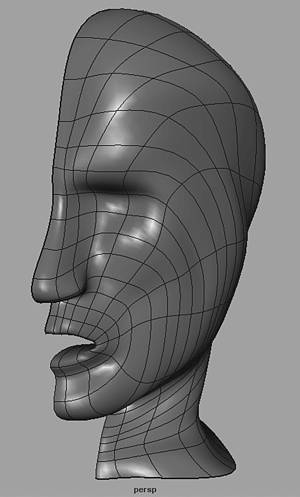
When moving many CVs simultaneously, you may want to use the Proportional Modification tool. This can enable you to shape your head more naturally, by moving the CVs with a gradual falloff, instead of moving the entire group of CVs a constant amount. Do this by choosing Modify, Transformation Tools, Proportional Modification Tool  . Be aware that there are some new options for this tool in Maya 5. The World Modification Type is the traditional way of using the tool, which is based on moving only the group of CVs that you have selected. You will usually want to use either the Linear or Power options. The Linear option creates a falloff based only on the Distance value. Increase the value to move more CVs, which changes the shape of the falloff angle. Power has an additional Degree option that you can set with positive or negative values. Adjusting both the Distance Cutoff and Degree values changes the shape of the falloff angle. Setting negative values for the Degree option reverses the effect, making the CVs that are farther away from the tool move more than the center ones. With the tool activated, drag a selection box around some CVs on your model and translate the manipulator to see the propmod effect. In addition to using the World option, there is a new Parametric Modification Type that can be used with NURBS surfaces. In this case, only select a single CV to move. Other CVs on the NURBS patch around this CV will move based on their distance from the selected CV. All other options can be set in the usual manner. You can use this tool across seams to modify multiple NURBS patches. You also can create a similar effect by assigning deformers in the Animation module, such as a lattice, to your surfaces. Lattices can be assigned to objects or components and produce a similar falloff effect when the points of the lattice are manipulated. . Be aware that there are some new options for this tool in Maya 5. The World Modification Type is the traditional way of using the tool, which is based on moving only the group of CVs that you have selected. You will usually want to use either the Linear or Power options. The Linear option creates a falloff based only on the Distance value. Increase the value to move more CVs, which changes the shape of the falloff angle. Power has an additional Degree option that you can set with positive or negative values. Adjusting both the Distance Cutoff and Degree values changes the shape of the falloff angle. Setting negative values for the Degree option reverses the effect, making the CVs that are farther away from the tool move more than the center ones. With the tool activated, drag a selection box around some CVs on your model and translate the manipulator to see the propmod effect. In addition to using the World option, there is a new Parametric Modification Type that can be used with NURBS surfaces. In this case, only select a single CV to move. Other CVs on the NURBS patch around this CV will move based on their distance from the selected CV. All other options can be set in the usual manner. You can use this tool across seams to modify multiple NURBS patches. You also can create a similar effect by assigning deformers in the Animation module, such as a lattice, to your surfaces. Lattices can be assigned to objects or components and produce a similar falloff effect when the points of the lattice are manipulated. Refining the Radial Head Without Manipulating CVs One limitation of NURBS surfaces is that the control vertices or CVs do not sit directly on the surface curves, but instead sit on the hulls. This can make it difficult to tell which CV controls a particular part of the surface. In complex areas of the face, such as in the nose and mouth areas, CVs sitting on hulls can overlap each other. On a closed mouth, for instance, the CVs for your character's bottom lip will often be higher than the CVs for your character's top lip. This can be confusing, making it difficult to select the right CV for editing. You can use the arrow keys to pickwalk over the surface and eliminate some of this confusion, but you should also be aware of some modeling techniques and tools that enable you to manipulate NURBS surfaces without directly manipulating CVs on the hulls. Although the CVs do not sit directly on the NURBS surface, there are points that do sit on the surface, called edit points (EPs). Unfortunately, the EPs on a NURBS surface cannot be manipulated. However, you can manipulate EPs on a NURBS curve. Therefore, you manipulate points on the surface by using a history connection to creation curves for the NURBS surface. Do this on your half-head by copying out the surface curves that radiate around the mouth, usually the V direction, and then loft the curves to re-create the surface with a history connection. Delete or hide the original half-head, and group all the NURBS curves under one node so that you can select them all simultaneously. With the curve group selected, in component mode you can then turn on EPs and turn off CVs in the component selection filter bar. This enables you to select and manipulate the EPs on the curves, which will deform the surface of your half-head through the history connection (see Figure 2.10). When you have finished manipulating the EPs, just delete history on the surface to remove the connection and delete the creation curves. 2.10. By using the history connection between curves and a lofted surface, you can manipulate EPs to refine your model. 
You can use a couple of valuable modeling tools to manipulate a NURBS surface without having to manipulate CVs directly. The first is the Sculpt Surfaces tool, which is activated by selecting your half-head, and choosing Edit NURBS, Sculpt Surfaces Tool . In the resulting Artisan Tool options box, adjust the settings for manipulating the surface (see Figure 2.11). For modeling an organic character, you should in most cases choose the first or second round brushes that have a smooth falloff. In the perspective view, painting with the Sculpt Surfaces tool gives you a very intuitive way of pushing and pulling points to refine the shape of your character's head after you have finished creating the main isoparm structure. Set the brush upper radius or hold down the B key to size your brush interactively. You should only set the lower radius if you are using a pressure-sensitive stylus. Adjust the Opacity and Max Displacement sliders to set how many points on the surface will move when you paint a stroke. In addition, set the Operation option to move points in the direction you want. In most cases, you will want to use the Normal option to push and pull points on your model perpendicular to the surface, just like you would if you were shaping a piece of clay. However, there will be times when you should use the other options for moving points according to the first normal direction of a stroke, or according to the global axis, or according to the U and V directions on the surface. Experiment with these different settings to see how they deform the surface. Use the Smooth and Erase operations to soften or reduce the effects of pushing and pulling points on the surface. Finally, if you need to move all the points on a surface in particular directions, set all your options as needed and click the Flood button. 2.11. The Sculpt Surfaces tool enables you to push and pull the surface using artisan brushes. 
The other tool that you can use to manipulate a NURBS surface without directly selecting CVs is the Surface Editing tool. This is one of the most useful modeling tools in Maya, and every modeler should be thoroughly familiar with how to use it. With your half-head selected, activate this tool by choosing Edit NURBS, Surface Editing, Surface Editing Tool. The tool itself is an icon that sits directly on your NURBS surface with several handles sticking out of it (see Figure 2.12). The only option for this tool is the size, which you can adjust by double-clicking the Surface Editing tool's icon on the toolbar. When using this tool, it is best to enlarge the perspective view to full screen and make sure you have Shading, Shade Options, Wireframe on Shaded turned on. This enables you to see the structure of your surface in shaded view as you manipulate the tool handles. The main center icon is a large square sitting directly on the surface that can be translated to move that part of the surface. Click and drag the small blue cube next to this square to slide the tool across the surface to another position on the surface. There is also a long handle coming out from the center square icon that has a blue sphere, a second blue square, and another small blue cube icon sitting on it. This handle is oriented along one of the three main directions of the NURBS surface. Clicking the blue sphere changes the orientation of the handle to face along the U, V, or normal direction on the surface. (The normal direction is perpendicular to the surface and is sometimes referred to as the W direction.) Moving the square icon on the handle rotates points on the surface, whereas moving the small blue cube enables you to scale points on the surface. Manipulating these handles can give you a high degree of control over refining your NURBS character's skin to exactly the way you want it, without ever having to directly manipulate CVs. 2.12. Manipulate handles on the Surface Editing tool to manipulate the surface directly in a variety of ways. 
Completing Your Character's Head After refining your half-head so that it is close to finished, make it into a whole head to complete the details and add asymmetrical variations. Because an instance cannot be made into a normal surface, select and delete the instanced side of the head. Then duplicate the remaining half of your head, being sure to set the duplicate options to Copy rather than Instance and scale it 1 in X to mirror it to the other side. However, make sure the points running vertically down the open edges of each head are straight before duplicating. If they are not, select the hulls on the top and bottom edges and scale them in X until they are in a vertical line. Also, to ensure that the new half ends up in the right place in X, make sure you line the center of your half-head up with the open edge. To connect the two halves together, you just have to Shift-select both surfaces and attach them using Edit NURBS, Attach Surfaces. To attach both sides without adding any extra isoparms, set Blend as the Attach Method, with a .5 in the Blend Bias value. If you have any problems attaching, such as the top edge of one half-head attaching to the bottom edge of the other, you will need to specify the edges to attach by selecting the two top-edge isoparms in component mode before attaching. Keep in mind that attaching the two halves of the head does not make it into a closed surface. The top edges on the forehead are attached, but the bottom edges on the chin remain open. It is important to close the head surface at the chin so that it doesn't split apart when the surface is deformed during animation (see Figure 2.13). Do this by selecting your character's head and choosing Edit NURBS, Open Close Surfaces . It is often best to use the Blend option here also. Be aware that you only want to close the direction on the surface that will make the head a continuous surface at the chin, and not close the direction that creates the open mouth and neck. In most cases, this will be the V direction, but this really depends on your individual model. Notice that closing the head surface at the chin moves the seam to the side of the face. It is best to move it back to the center by selecting the isoparm on the middle of the chin and choosing Edit NURBS, Move Seam. Having the seam directly in the middle of the chin keeps both sides of the head symmetrical in structure, which makes it easier to continue modeling and for texturing. For instance, a symmetrical surface is required to use the Sculpt Surfaces tool's Mirror option, which creates two brushes on each side of the face while you sculpt in order to make symmetrical adjustments. 2.13. Even after attaching the two halves of the head, the seam at the chin is still open. It should be closed so that it doesn't show up when the face is animated. 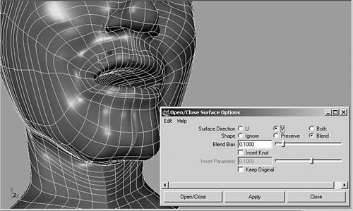
It is best to create the eyeballs of your character before creating the eyelids, because you can then use the eyeballs as guides for shaping the eyelid sockets. Begin the eyeballs by creating a primitive sphere with the axis facing in Z. Create a second sphere that is offset to intersect the front of the first sphere and perform a subtract Boolean operation to carve out the colored part of the eye. This creates a separate indented surface that you can texture easily, and the surface will catch light on its edge. Finally, make the black iris of the eye as a small squashed sphere that fits in front of the indented colored section. The advantage of making the iris as a separate piece of geometry is that it can be scaled easily to make it larger and smaller, just like a real iris. If you really want to make the eye realistic, make one last sphere that encloses all the other parts of the eye. This sphere should be made completely transparent, but with a high specularity so that it reflects light, especially on the curved area that encompasses the iris. To finish your eye, make the transparent sphere the parent of all the other eye parts so that they can all be animated together easily. The two main styles of eyelids you see on 3D characters are cartoon, which are noticeably separate surfaces from the main head, and realistic, which appear to have seamless continuity with the main head. To create a cartoon eyelid, in the side view you draw a curve around your eyeball in a 90-degree arc with a small hook at the end, and then revolve the curve 360 degrees in Y (see Figure 2.14). This creates the top lid, which you can then duplicate to create the bottom lid. Scale the bottom lid slightly smaller than the top lid and rotate it in X to place it over the lower part of the eye. Animating the cartoon eyelids is done by just setting keyframes on their X rotations. 2.14. Create a cartoon eyelid by revolving a hooked curve in Y. The cartoon eyelid will be rotated to open and close. 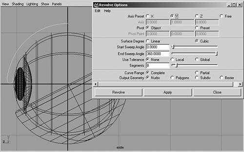
To fit the cartoon eyes onto your character's face, you can create a lattice around each eye. For instance, create a single group node parent named LtEyeGroup over the left eyeball group, and the two left eyelids. Then select the LtEyeGroup node and create a lattice by choosing Deform, Create Lattice in the Animation module. Set the lattice Division options to 2 for simple squashing and stretching, or to higher numbers for more extreme deformations. It is not necessary to turn on local mode, but group the base and lattice together so that you can make them child to your head skeleton when you create your animation rig. Leave all the other options turned off. Finish your cartoon eyeball by selecting the lattice group in the hypergraph view, and then in the perspective view translate the lattice group to the eye area of your main head. Once positioned, select and translate lattice points to fit the left eyeball and eyelids into the face as needed (see Figure 2.15). Be aware that the lattice deformation occurs on top of the transforms, so you should still be able to rotate your eyeball and eyelids in the deformed state, without any intersection problems. For this reason, you should not delete the lattice after deforming the eyeballs into place, because then they won't close correctly. 2.15. Using a lattice to fit the cartoon eyeball into the eye socket enables you to still rotate the eyelids without intersection problems. 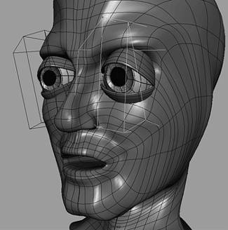
To create more realistic eyelids, you need to create a radial eye patch over each eyeball. You can do this in a variety of ways, including modeling it from a primitive sphere in a similar manner to the way you modeled the mouth on the main head surface. However, another technique is to make the head a live surface and draw a curve on it around the eye socket area. Use a cubic EP curve that you start and end at the same point under the brow. After creating, close the curve with a Blend set to a .5 Blend Bias. Then with the surface curve selected, choose Edit Curve, Duplicate Surface Curves to separate it from the main head. Make sure your eyeballs are placed as close as possible to their final position in relation to the face, and then use them as a guide for placing additional eyelid curves. Turn off the live surface head and duplicate the surface curve several times, moving and scaling each duplicate to contour the surface of your eyeball (see Figure 2.16). Pull the last few curves back to create the edge of the eye opening. After placing all your curves correctly, Shift-select all the curves in order from the surface curve to the last one on the edge of the eye and loft the curves to create the eyelid patch. 2.16. Create a realistic eyelid by drawing a curve on your head surface, and duplicate it several times to contour the eyeball. Then loft the curves to create the eyelid patch. 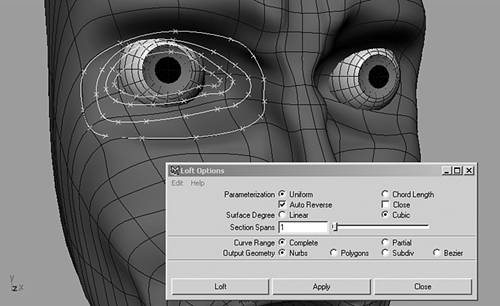
Be careful not to let the isoparms on your eyelid twist too much as they go from the head surface to the eye socket. You can group the creation curves to continue refining the patch by moving points on the curve using the history connection. At some point, you want to delete history on the eyelid surface, and add or delete isoparms as necessary to clean up the surface. It is important when you are building NURBS surfaces to space the isoparms as evenly as possible across the surface. Additional isoparms should only be added to create changes in direction on the surface, to harden an edge, or to create a wrinkle. On your eye patch, for instance, the isoparms that radiate out from the eye socket should be evenly spaced, but you may add some extra isoparms in the other direction to create the eye fold. You can create a more regular surface by rebuilding the surface as Uniform parameterization, but that can sometimes adversely remove important details. It is sometimes better to just select the isoparms you want to remove and delete them. You also can create a NURBS ear as a separate radial patch that sits on top of the main head surface. Another way to create radial surfaces is to revolve an EP curve a full 360 degrees, and then modify the surface into the shape you want. Draw a curve that creates the basic shape of the cavity and outer edge of the ear, revolve it, and then modify the resulting surface to have more of an irregular ear shape (see Figure 2.17). Proportional modeling or a lattice makes it easier to form the ear. Like the eye patch, you need to create tangency between the outer edge of the ear patch and the main head surface. Be aware that using the V key to snap CVs to other CVs on the middle of a NURBS surface will not create tangency between the surfaces. The reason for this is that the two surfaces have very different isoparm structures, and because the CVs you are snapping together are not sitting directly on the surface. Snapping CVs only works well on the edges of two NURBS surfaces that have the same UV structure, such as in a multipatch model as described later in this chapter. Lofting from an EP curve that was drawn on a live surface,to however, produces better tangency because the EPs can be drawn directly on the surface. Keep in mind that even though you may have created the body parts separately, at any time you can copy out the isoparms to reloft with a curve drawn on the main surface. This enables you to make a good connection between the surfaces that will appear continuous. Due to the differences in the drawn and copied curves, however, the resulting NURBS patch will have extra isoparms that should be cleaned up. Do this by rebuilding the surface, or by manually deleting isoparms after deleting history on the surface. 2.17. Revolve a curve to create a basic ear shape, and then modify it to form a basic ear for your character. 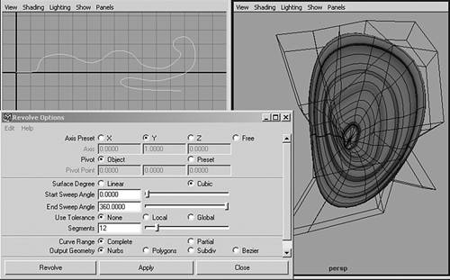
Exercise 2.1
Create Your NURBS Character Head This exercise gets you started on creating the head for your NURBS character. It takes you through the process of modeling a single-surface main head with a radial mouth and two separate radial eye patches. In addition, you add some eyeballs and separate radial ear patches to complete the head. Begin your character's head by carving out a mouth and neck from a simple NURBS sphere. Choose NURBS Primitive, Sphere , and set the object pivot Axis option to Z. Make sure you are creating a complete sphere with an End Sweep Angle of 360 degrees, and a Cubic surface degree for a smooth NURBS surface. Finally, set the Sections and Spans options to 12, and click the Create button. You should see a sphere with its poles pointing forward and backward in Z. Scale the resulting sphere in X so that it is around 6 grid spaces wide, and then scale it in Y so that it is slightly taller than it is wide. When the sphere is sized correctly, choose Modify, Freeze Transformations. Right-click the sphere and choose Isoparm to switch to component mode with the isoparms visible. Click one of the isoparms surrounding the front pole, and drag to create a yellow dotted line between the first and second isoparm. Choose Edit NURBS, Insert Isoparms , and make sure the options are set to insert the isoparm At Selection. Also make sure the Increase by Multiplicity option is set to only 1, and click Insert. This creates an extra row of isoparms on the front of the sphere, close to the area where the lips will be formed. Then right-click the surface to switch to Control Vertex, and in the side view drag a selection box around the front pole and first two rows of CVs. Translate the selected CVs back in Z past the center of the sphere (see Figure 2.18). Do not line them up with any other rows of CVs, so that they will be easier to select again if needed. Then select the next row of CVs on the front of the sphere, and scale them down in X and Y to form the mouth opening. When the CVs are in the shape of a mouth, use the Ctrl key to unselect the side vertices in the front view, and translate the top and bottom vertices forward in Z to form a top and bottom lip. To place the mouth lower on the face, in the side view select the several rows on the front of the sphere around the mouth, Shift-select the CVs at the back of the mouth, and translate them all down slightly. 2.18. Add an isoparm to the front of your sphere, and translate back the first few rows of CVs to carve out the mouth cavity. 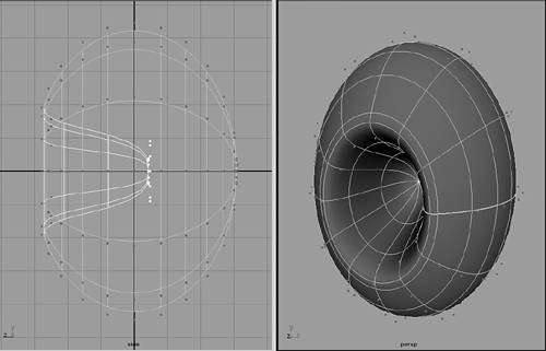
Add a couple more isoparms around the mouth opening to further define the lips and chin. In the side view, select and translate CVs to curve the isoparms around the mouth, which will ultimately create the nose and chin protrusions. Build the details of the face gradually by adding isoparms one at a time, and then move the new CVs into place. In the front view, you want to scale the points on both sides of the face so that the isoparms are oriented more vertically on the chin and upper lip. A row of isoparms should be added on either side of the center isoparm on both the lower and upper parts of the face to better define the bridge of the nose and the chin. While going through the process of adding isoparms and positioning CVs, you can press the G key to repeat the insert isoparm operation. When roughing out the basic head shape at this early stage, try to use mainly the front and side views to make symmetrical changes. At this point, however, do not be concerned if isoparms on both sides of the face are not perfectly symmetrical, because you are going to discard one half of the head in the next stage of the process. To form the neck of your character, in the side view select the second vertical isoparm on the back of your head, and choose Edit NURBS, Detach Surfaces. This should cut the head into two pieces. Select and delete the back piece to create a circular hole in the back of the head. Switch to hulls component mode, and select the two hulls closest to the detached hole. In the side view, translate, rotate, and scale the hulls downward so that they create a horizontal neck opening. Modify the hulls at the middle of the head so that they continuously rotate toward the neck, and then insert and transform additional isoparms between the head isoparms and the base of the neck to improve the shape. Switch to control vertex mode to move CVs in the neck and chin areas to create a smooth transition from head to neck. Also, move CVs on the top of the head to further approximate an accurate head shape (see Figure 2.19). 2.19. After rotating the back of the head down to create the neck opening, continue adding isoparms and moving points to create a smooth transition from head to neck. 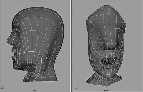
After creating the basic head and neck structure, you can begin developing the face of your character. Because the face can be symmetrical through most of the stages of the modeling process, you can use the popular technique of cutting your head in half to work on only one side of the face. It is much easier to do this than trying to select and move CVs on both sides of the face. Remove one half of your character's head by selecting the isoparms going straight up and down the center, and choose Edit NURBS, Detach Surfaces. This should cut the head into two equal pieces. In the front view, select the piece on the left side and click the Delete key. It will be difficult to achieve accurate proportions if you can't see both sides of your head while modeling, so select the remaining half and choose Edit, Duplicate . Set the Duplicate Geometry Type options to Instance, and set the first Scale field to 1. Clicking the Duplicate button creates an instance of your half-head and scales it 1 in X to mirror it to the other side. An instance has no component structure of its own, but instead takes its shape from the source object you duplicated. This causes moving components on the original surface to move the same area on the instance. To try this, select and translate some CVs on your original half-head. Notice that the same CVs become highlighted on the instance, and they are edited to reflect the changes you make to the source object (see Figure 2.20). 2.20. Create an instance copy of your half-head that is scaled 1 in X to see both sides update while you are modeling half the head. 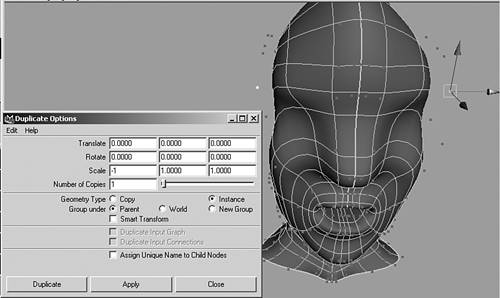
Before continuing to model your head, set up your Maya interface for modeling the face more easily. First, on the top menu bar of your front view, adjust the clip plane by choosing View, Camera Attribute Editor. In the Camera attributes for the front view, set the far clip plane to around 100. Adjust the number as needed until it hides the back of your character's head, so you can only see and select CVs on the front of the face. Doing the same thing in the side view should not be necessary, however, because your model is cut in half. You also can create shelf buttons for frequently used clip plane settings by copying to the shelf the MEL commands Maya runs for them. After setting a clip plane, open the Script Editor and look in the gray History field to view the clip plane MEL command. For instance, the command for setting the front view's far clip plane to 100 should look like this: setAttr "frontShape.farClipPlane" 100; Highlight the code in the History field with your left mouse button and drag it to the shelf with the middle mouse button. This creates a shelf button that you can click whenever you want to change the front view's far clip plane setting. Create several buttons with different settings for the front view's far clip plane, such as 1000, 100, and 97. You can give the shelf buttons short text names by clicking the drop-down arrow to the left of the shelf to open the Shelf Editor. Pick the new button in the Shelf Contents list and type in a short name in the Icon Name field. In addition to creating far clip plane shelf buttons for the front view, you can create near clip plane shelf buttons that enable you to see and select only CVs on the back of your character's head. You also can create a shelf button to set your NURBS to a custom display resolution. Currently, pressing the 1 key sets your NURBS head to low resolution in both wireframe and shaded modes, and pressing the 3 key sets the NURBS head to high resolution. The problem with this is high resolution shows too many interpolated isoparms in wireframe mode. To set a custom resolution that shows fewer isoparms in wireframe display mode while still looking smooth in shaded display mode, you must modify the MEL commands shown in the History field when you do both operations. Your custom code will set the NURBS wireframe display resolution to be low, while also setting your shaded resolution to be high. Do this in the Script Editor by finding the command that occurs when you press 1, which should look like this: displaySmoothness divisionaU 0 divisionsV 0 pointsWire 4  pointsShaded 1; pointsShaded 1; Highlight the command and middle-mouse drag the line of code to the shelf. Then to customize the code, open the Shelf Editor, click the new command in Shelf Contents, and switch to the Edit Commands tab. Then change the pointsShaded value to 4, so the command reads like this: displaySmoothness divisionaU 0 divisionsV 0 pointsWire 4 pointsShaded 4; Click the Save All Shelves button to exit the Shelf Editor. Finally, try out your new button. Selecting your head model and clicking the button should display it in low resolution when displayed in wireframe mode, and high resolution when displayed in shaded mode. You can then set your front and side views to wireframe mode, and set your perspective view to shaded mode to see as you work how your high-resolution skin looks. One other thing you can do to prepare for finishing your head is load your character designs from Chapter 1, "Creating Organic 3D Characters," into Maya as image planes. First, save your designs as separate JPEG images for the front and side views of your model blueprints, and then load them into the front and side views to use as image plane guides when modeling. For instance, open the front view's Attribute Editor again, and open the Environment section. Click the Create button to create an image plane for the front view. Inside the image plane's attributes, click the folder icon next to the Image Name field to load your front character design image. Set the image plane Display option to looking through camera, which will only display it in the front view. To adjust the size and placement of the image plane, change the Center, Width, and Height options in the Placement Extras section. For instance, you can move the image plane forward in Z by typing in a positive number in the third Center field. Or, make the image plane larger by typing bigger values in the Width and Height fields. You can also adjust these numbers in the channel bar under the front camera's Inputs. Keep in mind that you also could create a primitive NURBS plane with a setting of 1 for the U and V patches and assign a file texture to it. Do this by creating a Lambert material in the hypershade view, and assign your model blueprint as a file texture to the Color attribute. You can then use it as modeling guide by turning on hardware texturing in shaded mode in any of the views. One advantage of this is you can easily transform the plane to fit your model, or rotate the plane to unusual angles, such as for a three-quarters view of your character's head. The disadvantage is that the guide doesn't show up in wireframe mode, but must be used in hardware texture shaded mode. Either way, using image planes or file-textured planes is important for making sure you model the basic proportions correctly for your character's skin (see Figure 2.21). After adding all your modeling guides, you are ready to start refining your head model. 2.21. You can use image planes or file-textured planes to use your character model blueprints as guides for modeling your character's skin (character design and model by Carla Merrell). 
Begin refining your half-head by inserting isoparms and manipulating CVs. When manipulating hulls or CVs, use the arrow keys to pickwalk across the surface of your character's head. This is the best way to find your way around the U and V of the surface, by using the arrows to take you to the next CV in each direction. Work on refining all parts of the head, building the details gradually, and being careful not to add too many isoparms in any one area. You want a fairly even spacing of isoparms across the entire surface, so avoid creating areas where the isoparms bunch together or areas where the isoparms are too spread out. Later, after you have roughed out all the basic proportions evenly, you can add extra isoparms closer together to harden an edge, such as to better define the edge of your character's lips. Try to simplify the surface down to the minimum number of CVs for defining each feature. For instance, a basic nose shape can be defined by a maximum of five vertical isoparms (see Figure 2.22). The first is the center isoparm that defines the profile of the nose. Place an isoparm next to this one to define the bridge and ball of the nose, as well as to pull up an indention for the nostril. The next isoparm should create the side of the nose, and the one after that should flare out the edge of the nostril. Finally, the fifth isoparm defines where the nose connects to the rest of the face. This last nose isoparm should create the roundness of the edge of the nostril, by pushing skin back into the cheek. While creating your character's nose, make sure you orient the vertical isoparms in the cheek area so that they wrap back toward the eye area as much as possible. It is also important to make sure you orient the isoparms that radiate around the mouth so that they are horizontal on the nose and forehead. Ideally, they should contour the brow line and forehead wrinkles. At this point, do not create any eyelids and eye sockets, because these will be done using separate radial patches. Just push the surface back in the eye area to create an indention that the eyeball will sit within and the eye patches will sit on top of. 2.22. When roughing out the proportions of your head, try to add only the number of isoparms required to define each feature. For instance, use only five vertical isoparms to define the basic nose shape. 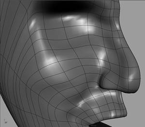
After adding enough isoparms to define the basic structure of the half-head, you can begin to use the other tools and techniques described earlier in this section to manipulate the surface without having to manipulate CVs directly. These include the Sculpt Surfaces tool and Surface Editing tool in the Edit NURBS menu, as well as the technique shown for manipulating EPs on curves that are copied from the U or V of your surface and lofted with a history connection. When you are happy with your basic half-head shape and features, you need to make it into a seamless whole head. First delete the instance half-head, because it cannot be used as an independent surface. Then rebuild your half-head to ensure that it can be attached correctly. Do this by selecting the surface and choosing Edit NURBS, Rebuild Surfaces . Set the Rebuild Type option to Uniform, the Parameter Range to Keep, the Direction to U and V, and the Keep option to CVs. Make sure you are also creating a cubic surface in both directions, and click the Rebuild button. These options should make your half-head a uniform surface, while not changing the isoparm structure. If you make sure your head is a uniform surface, you can most likely avoid any error messages when you attach and close the seams on your character's head. Then duplicate your half-head again, but be sure to set the duplicate options to create a Copy rather than an Instance. You also want to scale the copy 1 in X, which you can do by setting it in the duplicate options, or done manually in the Channel Box. Keep in mind that scaling 1 in X is mirroring the half-head in X based on the center position. To have the two sides of the head line up perfectly, the open center edge of your half-head and its center must be at 0 on the X-axis. Make any needed adjustments by scaling the center row of CVs to line them up correctly or by moving the object center in insert mode, before duplicating and mirroring your half-head. After you have lined up your two half-heads as closely as possible, attach the two halves by right-clicking to switch to isoparm selection mode, and then drag a selection box around the isoparms on both halves that overlap on the center of the forehead so that they turn yellow, and choose Edit NURBS, Attach Surfaces . Explicitly selecting the isoparms on both surfaces that you want to attach should force Maya to attach the correct open edges. Otherwise, Maya might try to connect the forehead edge of one half to the chin edge of the other half, depending on the UV directions of each surface. In the Attach option box, set the Attach Method option to Blend, and type .1 into the Blend Bias option field (see Figure 2.23). Click the Attach button to make the seam at the forehead disappear as the two halves are attached. 2.23. When attaching the two halves of your head, you can avoid surface twisting problems by selecting the isoparms you want to attach. 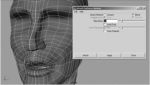
If you have any problem attaching, such as a twisting of surfaces, you should make sure the U and V are going in the same directions on each surface. You can check this by Shift-selecting both surfaces and turning on their surface origins to see a colored representation of the U and V directions on the surfaces. With surface origins turned on, a red edge shows where the U direction begins on each surface, and therefore also indicates the direction that the U is going. The start of the V direction is indicated by a green edge. To have both half-heads going in the same direction, the red line would need to be on the top edge on one half, and on the bottom edge on the other half, with the blue normal direction going outward on both halves. This ensures that the surfaces are going in the same direction, and should make them always attach correctly. To make this adjustment on one of your half-heads, select it and choose Edit NURBS, Reverse Surface Direction . In the options box, try reversing the U or V individually. Completely changing the directions on the surfaces by using the Swap option is usually not necessary on a mirrored head. When the surfaces are going in the right direction, select the isoparms on the forehead edges and try attaching them again. Even though the halves are attached, they are not completely merged into one continuous head. There is still an open seam at the chin that needs to be closed so that the surface won't separate during animation. Do this with the head still selected by choosing Edit NURBS, Open/Close Surfaces . Set the options to close the head only in the direction that is radiating around the mouth. Closing in the wrong direction will close your neck opening. Try the V direction first, and if it is wrong, undo and choose the U. When the chin seam closes, you will see it move from the center to the side of the chin. Move it back to the center of the chin by selecting the center chin isoparm and choosing Edit NURBS, Move Seam. This is the point where you will get an error message if you did not rebuild your half-head to a uniform surface before attaching. If you do get an error message, undo the Open/Close Surfaces operation so that the seam is back on the middle of the chin, and rebuild the surface as uniform. Otherwise, the seam should move to the center of the chin when you do the Move Seam operation, which will be better for texturing and using the Sculpt Surfaces tool with the Reflection option turned on. You can find this option in the Tool Settings box under the Stroke tab. This option will prove useful for making symmetrical adjustments to both sides of your character's face. Finally, name your finished head model HeadSkin, and delete history by choosing Edit, Delete by Type, History. The next step in modeling your head is to create eyeballs and radial eyelid patches. Hide your head so that it is not in the way and begin a NURBS eyeball by creating a primitive sphere with 10 spans and sections, and its axis pointing in Z. Duplicate the sphere, and translate the copy forward so that it intersects the front of the first sphere. Make sure you do not still have a 1 setting in the X scaling of your duplicate options, because this will affect the result of the Boolean operation. Position the spheres so that the area that the spheres intersect is the size that you want the colored part of your eyeball to be. Then choose Edit NURBS, Booleans, Subtract Tool. Click the first sphere and press the Enter key, and then click the second sphere to perform the Boolean operation. The second sphere disappears as the first sphere is carved out by a spherical indentation (see Figure 2.24). You can still select the second sphere in an outliner view to adjust the size of the carved-out area. 2.24. Intersect two spheres to do a subtract Boolean operation (left), which will carve out the colored section of your eye (right). 
When the colored area is the right size, select the Boolean node in the outliner and delete history. This deletes the original surfaces and makes the new Boolean surfaces into just two regular NURBS surfaces. Unparent both pieces of the eye from the Boolean node in the hypergraph view and delete it. Name the surfaces LtEyeWhite and LtEyeColor, and make LtEyeWhite the parent of LtEyeColor. Before going on to the other parts of the eye, right-click LtEyeColor to open the Attribute Editor, and increase the U and V resolutions of the surface. When you do a Boolean operation, the tessellation of the resulting surfaces is set lower than the resolution on the original spheres. To set it back up to the default resolution, open the Tessellation tab, and type a 4.5 value into the U and V Divisions Factor. This makes your eyeballs render at the same resolution as your other surfaces. For now, open a hypershade view and place a basic white Phong material on LtEyeWhite, and a basic colored Phong material on LtEyeColor. An indented surface for the colored part of the eye causes it to catch the light nicely, giving the eyes of your character a little life. Later, you should connect a ramp to the Color attribute of the colored part of the eye, or load a file texture to create a more realistic eye color. In addition, the indented surface creates a space to insert the black iris part of the eye as an object, rather than as a texture map. Do this by creating another sphere, translating and scaling it so that it fits inside the indented area (see Figure 2.25). Squash it in Z so that it is not a perfect sphere and doesn't intersect with the colored part of the eye. Place it so that it completes the roundness of the eye when seen in the side view. The advantage of using an object for the iris, rather than just a texture map, is that it will be very easy to animate the scaling to make the iris get larger and smaller. Assign a Lambert material to the iris, with all the color values brought down to black. Name this part of the eye LtEyeIris, and make it child to LtEyeColor. 2.25. Transform a squashed sphere so that it fits within the indented area to create the black iris for your character's eye. 
To finish the eyeball, create another sphere that you scale so that it surrounds all the other pieces of the eye. Add a couple of isoparms on either side of the radial isoparm that is closest to the edge of the colored part of the eye. Because a real eyeball is not perfectly round, you should scale these isoparms so that they form a ridge contouring the colored part (see Figure 2.26). This part of the eyeball should be mostly transparent, so create a Phong material that has the Transparency, Specular Color, and Cosine Power attributes pulled almost all the way up. This creates a glassy material with a small, strong highlight, which brings out the edge you created around the colored area. Name this part of the eye LtEyeWhole, and make it parent to LtEyeWhite. Finally, create a point light in your scene and render the eyeball to check how it looks. Then unhide your head and move the left eye hierarchy into the left indented area on your head. Place it where you think the eye should go, and scale it as needed. Duplicate it when you get it into place, name the new eyeball appropriately, and translate it in X to position the other eye. Freeze transformations on both when they are in place. You can now use the eyeballs as guides for creating your eyelid patches. 2.26. Surround the eyeball parts with a transparent sphere that is deformed to have a ridge on the front (left). This produces a highlight around the colored part of the eye when rendered (right). 
Create a radial NURB eye patch by drawing a curve on the surface of your main head that can be lofted with other curves that contour the eye. Duplicate the main head first, and name the copy LiveHead. With Live Head still selected, make it live by choosing Modify, Make Live. Using a copy will enable you to see the surface better in shaded view. Then draw an EP curve around the eye socket area by choosing Create EP Curve Tool . Make sure you are using a 3 Cubic degree setting with Uniform knot spacing. Start drawing the curve under the brow, and contour the isoparms on the face that form a rectangle around the eye. Avoid adding too many points, but stay close to the resolution of the main head. Stop drawing the curve just before you return to the starting point, and press the Enter key to create the curve (see Figure 2.27). Then close the curve by choosing Edit Curves, Open/Close . Set the close Shape option to Blend with a bias value of 0. When the curve is created deselect it, and turn off the live surface by choosing Modify, Make Not Live. 2.27. Draw an EP curve around the eye socket area on your live radial head to begin creating an eye patch. 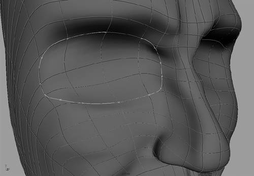
If you look in a hypergraph view, you will notice that there is no transform node for the curve you just created. It is actually part of the head surface, and must be duplicated to create a separate curve from the head. Just select the surface curve and choose Edit Curves, Duplicate Surface Curves. This creates a curve that has its own transform node in the hypergraph view. Name the new curve EyelidCurve1, and duplicate it to create a second curve named EyelidCurve2. Translate and scale EyelidCurve2 so that it is slightly smaller than EyelidCurve1, and offset so that it rises off the surface toward the front of the eyeball. Continue duplicating and transforming to create the rest of the curves for the eyelid. Scale each duplicated curve so that it is smaller than the previous one, and translate them so they form the eyelid shape around the colored part of the eyeball. The curves should gradually rise away from the face, and then go back in around the eyeball to create a lip for the eyelid. To better see the surface you are creating, loft all the curves and group the curves to use the history connection to refine the lofted surface. When Shift-selecting the curves to perform the loft, make sure the first curve you select is the curve you created on the live head surface, and the last curve you select is the one closest to the eyeball. Then choose Surfaces Loft and set the options to Uniform parameterization. Do not close the surface, and make sure you are creating a complete cubic NURBS surface. Select the curve group to move EPs on the curves, which will in turn modify the eyelid surface. Try to make sure the isoparms radiate evenly from the eye socket, and make sure you remove any twisting or stretching of isoparms around the eyeball. Then delete history on the surface and hide the creation curves group. Add or delete isoparms as needed to create a clean surface structure, complete with eye fold (see Figure 2.28). If necessary, rebuild the eye patch as a uniform surface in the direction that radiates around the eye, setting the Uniform rebuild divisions to the same number as will line up with the corresponding isoparms on the face. This makes it easier the line up the surfaces when you create a multipatch head later in this chapter. When finished, delete history and duplicate your finished eye patch, scaling it 1 in X to mirror it to the other side of the face. Name the eye patches of your character's head LtEyePatch and RtEyePatch. 2.28. Clean up your finished eye patch so that the isoparms are straight, and match the head isoparm structure as much as possible. 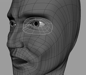
You also can create a simple ear as a radial patch that sits on top of the head. This time, you create the patch by revolving a profile curve that you draw in the top view. Draw the curve so that it defines the basic hole and edge of the ear. Make sure you start the part of the curve that creates the ear cavity at the 0-axis, and draw the rest of the curve down the negative Z-axis. Revolving the profile curve creates a very regular surface that looks more like a hubcap than an ear. Use the Proportional Modification tool or a lattice as described earlier in the chapter to modify CVs with a falloff, and shape the surface to more resemble an ear. Keep in mind that there are more complicated ways of making ears, such as making nonradial ears that are composed of multiple patches. However, ears are usually minor details on the head that are not scrutinized much by viewers. Often, they are obscured or entirely covered by hair. So normally it is not necessary create highly detailed ears that are completely anatomically accurate. After revolving your curve, delete history on the surface and use all the tools and techniques described earlier in the chapter for moving points to refine the ear shape. Add isoparms as needed while you are working. After creating the ear patch, position it on the head and copy out the surface curves. Then make the main head a live surface and move EPs on the ear curve that should connect the ear to the head. The EPs should snap to the head surface, which will improve tangency. When done, turn off the live head surface and reloft the ear curves. Finally, duplicate and scale the finished ear patch to mirror it to the other side of the head, and name the surfaces LtEarPatch and RtEarPatch. Even though the ears are a minor detail on your character's head, they are important to completing the look of your finished radial head (see Figure 2.29). 2.29. Shown here is an example of a finished radial ear patch (character model by Travis Burcham). 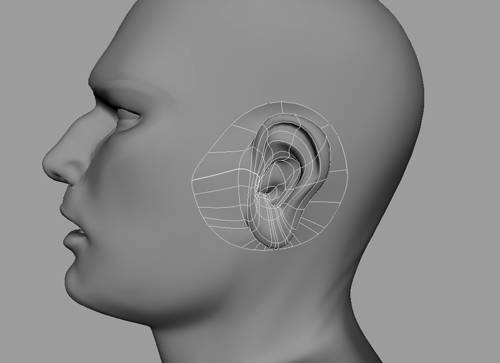
|
|