12.3 Parcel Router Problem
12.3 Parcel Router Problem
The parcel router problem is concerned with the simple parcel-sorting device depicted in Figure 12.7.
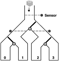
Figure 12.7: Parcel router device.
Parcels are dropped into the top of the router and fall by gravity through the chutes. Each parcel has a destination code that can be read by sensors. When a parcel passes a sensor, its code is read and the switch following the sensor is set to route the parcel to the correct destination bin. In this simple router, there are only four possible destinations numbered from zero to three. The switches can only be moved when there is no parcel in the way. The problem was originally formulated as a simple case study to show that specifications are not independent of implementation bias (Swartout and Balzer, 1982). It was called the Package Router problem. We have renamed packages to parcels to avoid possible confusion with Java packages.
In the following, we develop a timed model of the parcel router and then implement a simulation based on the model. We ignore gravity and friction and assume that parcels fall at a constant rate through chutes and switches.
12.3.1 Parcel Router Model
The overall structure of the parcel router model is depicted in Figure 12.8. Parcels are fed into the routing network by a generator process and emerge from the network into one of four destination bins.
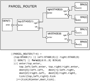
Figure 12.8: Parcel router model structure.
GEN
The generator process GEN, defined below, generates a parcel every T units of time. Each parcel contains the number of its destination. The generator picks a destination for a parcel using non-deterministic choice.
range Dest = 0..3 set Parcel = {parcel[Dest]} GEN(T=3) = (enter[Parcel] -> DELAY[1] | tick -> GEN), DELAY[t:1..T] = (tick -> if (t<T) then DELAY[t+1] else GEN).
BIN
The destination bins are property processes that assert that the parcel delivered by the routing network to the bin must have the same destination number as the bin.
property BIN(D=0) = (dest[D].parcel[D] -> BIN) +{dest[D][Parcel]}.
STAGE
We have subdivided the routing network into three stages. Each stage has an identical structure. The parameter to a stage determines its level in the routing network. The structure of the STAGE composite process is depicted in Figure 12.9.
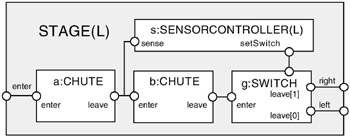
Figure 12.9: STAGE structure.
The composition expression which Figure 12.9 represents graphically is:
||STAGE(L=0) = ( a:CHUTE || b:CHUTE || g:SWITCH || s:SENSORCONTROLLER(L) )/{ enter/a.enter, b.enter/{s.sense,a.leave}, g.enter/b.leave, s.setSwitch/g.setSwitch, left/g.leave[0], right/g.leave[1], tick/{a,b,g}.tick } >>{enter,left,right,tick} @{enter,left,right,tick}.
CHUTE
Each physical chute in the physical device is modeled by a set of CHUTE processes. A CHUTE process models the movement of a single parcel through a segment of a physical chute. To model a chute that can have n parcels dropping through it, we need n CHUTE processes. In modeling the system, we use two processes and so we are modeling a physical chute that can accommodate only two parcels. The CHUTE process is given below:
CHUTE(T=2) = (enter[p:Parcel] -> DROP[p][0] |tick -> CHUTE ), DROP[p:Parcel][i:0..T] = (when (i<T) tick -> DROP[p][i+1] |when (i==T) leave[p] -> CHUTE ).
A parcel enters the chute and leaves after T units of time. We must be careful when composing CHUTE processes that the resulting composition has consistent timing. For example, the following system has a time-stop.
||CHUTES = (first:CHUTE(1) || second:CHUTE(2)) /{second.enter/first.leave, tick/{first,second}.tick}. It happens when a parcel tries to enter the second CHUTE before the previous parcel has left. Time-stop in this context can be interpreted as detecting a parcel jam in the physical device. For consistent timing in a pipeline of CHUTE processes, each process must have a delay which is the same or greater than the delay of its successor.
SENSORCONTROLLER
This process detects a parcel by observing the action caused by a parcel passing from one CHUTE to the next. Based on the destination of the parcel, it computes how the switch should be set. This routing function depends on the level of the stage. Because the network is a binary tree, it is simply (destination≫Level)&1 (in this expression context, ≫ is the bit shift operator and & the bit-wise and operator). The function returns either zero, indicating left, or one, indicating right. SENSORCONTROLLER is not a timed process since we assume that detection of the parcel and computation of the route take negligible time. Each execution occurs within a clock cycle.
SENSORCONTROLLER(Level=0) = (sense.parcel[d:Dest] -> setSwitch[(d>>Level)&1] -> SENSORCONTROLLER).
SWITCH
During the time that a parcel takes to pass through the parcel switch, it ignores commands from the SENSORCONTROLLER. This models the physical situation where a parcel is passing through the switch and consequently, the switch gate is obstructed from moving.
range Dir = 0..1 //Direction 0 = left, 1 = right SWITCH(T=1) = SWITCH[0], SWITCH[s:Dir] = (setSwitch[x:Dir] -> SWITCH[x] //accept switch command |enter[p:Parcel] -> SWITCH[s][p][0] |tick -> SWITCH[s] ), SWITCH[s:Dir][p:Parcel][i:0..T] = (setSwitch[Dir] -> SWITCH[s][p][i] //ignore |when (i<T) tick -> SWITCH[s][p][i+1] |when (i==T)leave[s][p] -> SWITCH[s] ).
The SWITCH process extends the behavior of the CHUTE process with an additional component of its state to direct output and an extra action to set this state. SWITCH can be implemented by deriving its behavior, using inheritance, from the implementation of CHUTE.
Analysis
Having completed the definition of all the elements of the PARCEL_ROUTER model, we are now in a position to investigate its properties. We first perform a safety analysis of a minimized PARCEL_ROUTER(3). This system feeds a new parcel every three timing units into the routing network. This produces the following property violation:
Trace to property violation in BIN(0): enter.parcel.0 tick tick tick enter.parcel.1 tick tick tick enter.parcel.0 tick tick tick enter.parcel.0 tick dest.0.parcel.0 tick tick enter.parcel.0 tick dest.0.parcel.1
The trace clearly shows that a parcel intended for destination one has ended up in BIN zero. However, while it may be obvious to the reader why this has occurred, it is not clear from the trace since we have hidden the intermediate events that occur in each stage. We can elicit more information from the model in a number of ways. We can make internal actions visible and rerun the analysis or we can investigate the problem using the animator tool provided by LTSA. The second approach has the advantage that we do not need to modify the model in any way. We simply select STAGE as the target for analysis (with default level parameter as 0) and run the Animator using the following menu to specify the actions we wish to control.
menu TEST = {enter[Parcel],tick} The trace depicted in Figure 12.10 was produced by initially choosing an enter.parcel.0 action followed by three tick actions, then enter.parcel.1 followed by five ticks. This is the trace produced by the safety violation, without the subsequent parcel entries. The Animator trace clearly exposes the reason for the violation. The first parcel is still in the switch when the sensor detects the second parcel and tries to set the switch to direction 1. Since the first parcel is in the switch, the s.setSwitch.1 action is ignored and the switch does not change. Consequently, the second parcel follows the first in going to the left when it should have been switched to the right.
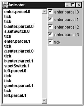
Figure 12.10: Animation trace for STAGE(0).
The physical interpretation of the problem is that parcels are too close together to permit correct routing. We can check this intuition by analyzing a system with a slower parcel arrival rate, PARCEL_ROUTER(4). Safety analysis finds no problems with this system and progress analysis demonstrates that the TIME property is satisfied.
In the next section, we describe a simulation of the parcel router based on the model. This implementation faithfully follows the model in allowing parcels that are too close together to be misrouted.
12.3.2 Parcel Router Implementation
The display for the parcel router simulation is shown in Figure 12.11. A new parcel for a particular destination is generated by pressing the button beneath that destination. Parcels that arrive at the wrong destination flash until they are replaced by a correct arrival. The speed of the simulation can be adjusted using the slider control to the right of the display. This controls the TimeManager described in section 12.2.2.
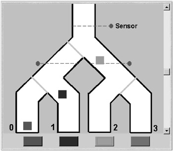
Figure 12.11: Parcel router applet display.
In describing the parcel router implementation, we concentrate on the interfaces and classes shown in Figure 12.12. These classes implement the timed behavior of the simulation. Display is implemented by the ParcelCanvas and Parcel classes. Each Parcel object is registered with the ParcelCanvas, which displays the parcel at its current position once per clock cycle. In addition, the ParcelCanvas displays the background and the current state of each switch. The Parcel and ParcelCanvas code can be found on the website that accompanies this book.
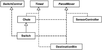
Figure 12.12: Parcel router classes and interfaces.
To permit flexible interconnection of Chute, Switch, SensorController and DestinationBin objects, each class implements the ParcelMover and SwitchControl interfaces listed in Program 12.8. The latter interface is required to allow switches to be connected to controllers.
Program 12.8: ParcelMover and SwitchControl interfaces.
interface ParcelMover { void enter(Parcel p) throws TimeStop; } interface SwitchControl { void setSwitch(int direction); } The Chute class listed in Program 12.9 is a direct translation of the CHUTE process defined in the previous section using the method described in section 12.2.1. If the current field is not null then the chute contains a parcel. After T clock cycles this parcel is transferred to the ParcelMover object referenced by the next field. This field is initialized when the configuration of chutes, switches, etc. is constructed by the ParcelRouter applet.
Program 12.9: Chute class.
class Chute implements ParcelMover, Timed { protected int i,T,direction; protected Parcel current = null; ParcelMover next = null; Chute(int len, int dir) { T = len; direction = dir;} // parcel enters chute public void enter(Parcel p) throws TimeStop { if (current!=null) throw new TimeStop(); current = p;i = 0; } public void pretick() throws TimeStop { if (current==null) return; if (i == T) { next.enter(current); // package leaves chute current = null; } } public void tick(){ if (current==null) return; //update display position of parcel ++i; current.move(direction); } } The Switch class listed in Program 12.10 is derived from Chute. A Switch object has references to the ParcelMover objects to its left and right. The setSwitch method sets the next field of the super class to one of these if there is no parcel currently occupying the switch. If there is, the command to switch is ignored, as in the model. Setting the next field means that when a parcel leaves, it is sent to the ParcelMover referenced by either left or right.
Program 12.10: Switch class.
class Switch extends Chute implements SwitchControl { ParcelMover left = null; ParcelMover right = null; private ParcelCanvas display; private int gate; Switch(int len, int dir, int g, ParcelCanvas d ) { super(len,dir); display = d; gate = g;} public void setSwitch(int direction) { if (current==null) { // nothing passing through switch display.setGate(gate,direction); if (direction==0) next = left; else next = right; } } } The SensorController class is listed in Program 12.11. Parcels pass through within a single clock cycle. The class is not aware of time and does not implement the Timed interface. Only model processes that have tick in their alphabets need to be implemented as Timed classes.
Program 12.11: SensorController class.
class SensorController implements ParcelMover { ParcelMover next; SwitchControl controlled; protected int level; SensorController(int level){this.level=level;} // parcel enters and leaves within one clock cycle public void enter(Parcel p) throws TimeStop { route(p.destination); next.enter(p); } protected void route(int destination) { int dir = (destination>>level) & 1; controlled.setSwitch(dir); } } The ParcelRouter applet class contains a set of methods that create and “wire together” the parts of the simulation. The method listed below creates an assembly that corresponds to the STAGE composite process of the model.
ParcelMover makeStage (ParcelMover left, ParcelMover right, int fallDir, // movement direction for parcel display int level, // 0 or 1 as in the model int gate // identity of gate for display purposes ) { // create parts and register each with TimeManager ticker Chute a = new Chute(16,fallDir); ticker.addTimed(a); SensorController s = new SensorController(level); Chute b = new Chute(15,fallDir); ticker.addTimed(b); Switch g = new Switch(12,fallDir,gate,display); ticker.addTimed(g); // wire parts together a.next = s; s.next = b; s.controlled = g; b.next = g; g.left = left; g.right = right; return a; } The method exhibits a pleasing correspondence with the STAGE model. The model process prefix names become object references and the model relabels become reference assignments.
The DestinationBin class, which may be found on the website that accompanies this book, accepts a Parcel object and displays it in a fixed position. When a new parcel arrives, the old parcel is removed from the display. Parcels that arrive at the wrong destination are flashed by hiding and revealing them on alternate clock cycles.
The reader is encouraged to run the PackageRouter applet and observe that its behavior is as predicted by the model. The restriction that only one-way interactions can be supported by the clocking scheme has not caused a problem in this example. Even though the interaction between Chute, SensorController and Switch requires more than one method call in a clock cycle, it is still a uni-directional interaction in which a chute output causes an input to another chute and a switch.
EAN: 2147483647
Pages: 162