6.2 RAID Levels
| RAID is defined in several levels, which describe different mechanisms for achieving increased performance and reliability. These are numbered starting at zero and going up to five (note that we do not count RAID 10; that is a combination of two already defined RAID levels). The first level of RAID, RAID 0, provides purely performance improvements, without increasing reliability at all, whereas RAID 1 mostly provides reliability improvement. RAID 2 uses a complex algebraic method to provide data reliability, and the other levels use parity-protected mechanisms to provide increased protection as well as performance improvements. The heart of parity-protected RAID systems (levels 3, 4, and 5) is a mathematically simple, reversible parity computation. Every commercial implementation of parity-protected RAID uses some variation on this algorithm. It involves taking the data in an entire stripe width and applying the bitwise exclusive-or function (XOR) to generate a parity bit: The XOR function has the properity of being reversible; if it is applied twice, the original data is regenerated. When any member disk in the system fails, the data can be computed by looking at the data on the surviving members : These volumes can sustain the failure of any one disk, and the reliability of a parity-protected array with n member disks can be given as: It is an extremely common misconception that parity-based RAID systems use a read-and-compare mechanism for reads. This is not generally the case. [1] There are robust error detection mechanisms at the disk and protocol level, and the overhead of such a read-and-compare system would be substantial.
Reliability can be increased by adding hot spare volumes in some RAID configurations, because in the event of one disk failing, a spare is immediately available (significantly reducing the MTTR). This reduces the likelihood , statistically, of data loss. Unfortunately, single-channel parity-protected arrays can suffer problems with controller failure, which appears to the host system as a failure of multiple disk drives . Disk arrays capable of being configured with redundant controllers are not subject to this problem. 6.2.1 RAID 0: StripingIn the first level of RAID, a number of physical disk drives are broken into stripes and addressed as a single logical unit. Each disk drive is divided into units called chunks , so that successive chunk - sized logical blocks are stored on consecutive disks. The chunk size is often called the interlace or stripe unit size . The stripe width refers to the chunk size multiplied by the number of disks in the array. Figure 6-1 shows how RAID 0 organizes data on a set of physical disks. Figure 6-1. RAID 0 disk organization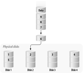 This organizational scheme means that, in many cases, the request is serviced by accessing several disks. Since sequential performance is dominated by the time required to transfer data from the platters, performance is optimal for requests that are the same size as the stripe width. This has the added advantage of distributing disk load evenly across all disks, reducing the utilization of each device in the array and improving random-access performance; recall that random-access performance is a function of seek time, and the less seeking we have to do, the faster we can fulfill the next request. Clearly, RAID 0 arrays universally improve disk subsystem performance.
Given a four-disk array with a 32 KB interlace, a 128 KB data request will be satisfied by reading four consecutive blocks, which will each come from a separate physical disk. The sequential performance of striped logical volumes approaches the aggregate bandwidth of each of the member disks times the number of disks in the array, given that there are limitations for no operating system, SCSI host adapters, array controller, etc. In this example, if each drive has an internal transfer speed of 6 MB/second, the array should be able to sustain about 24 MB/second. Random access performance is not substantially improved in single-threaded operation, because the governing factors for performance are the rotational and seek times of the member disks. In multi-threaded sequential operation, the various requests arrive at the member disks in a random order, and so the array exhibits an essentially random-access pattern. Performance generally does not improve linearly in RAID 0 arrays, since the member disks are not operated in spindle synchronization : each disk spins and seeks individually. We'll discuss spindle synchronization in more detail later, when we talk about RAID 3 arrays. In addition, RAID 0 devices do not improve performance when hot spots are accessed far more frequently than the rest of the volume, which causes an uneven I/O distribution on the member disks. One example is a named pipe that is written continuously, in which the near-continuous update to the last-modified time on the pipe causes a definite hot spot. One sneaky way around this problem is setting the sticky bit (accomplished by means of chmod +t filename ) on the pipe, which causes the system to defer updates to the entry's directory entry. This is slightly risky, because in the event of a system crash, the last modify date may be invalid; however, neither the data sent over the pipe nor the integrity of the filesystem are put at risk. The worst-case performance for a RAID 0 array occurs when the request size is very small and crosses a chunk boundary. Performance of a stripe will almost always be less than that of a single disk when the request size is 1 KB and crosses a chunk boundary; two drives are activated, and latency goes up while throughput is not improved. Choosing the stripe unit size is a somewhat complicated decision, and one that can have a substantial impact on performance. In random-access environments, performance is optimized by involving as many disks as possible. Since only one or two disks are involved in any given request, disk utilization is minimized when the number of disks is maximized. In such a case, the chunk size should be rather large -- about 128 KB. This step sounds counterintuitive, but the intent is to have as many drives active as possible, each satisfying a different request. Performance in sequential environments is optimized when the size of the I/O requests is equal to the size of the stripe width, and the chunk size is large enough to make the I/O overhead worthwhile. The performance benefits granted by RAID 0 do not come without cost. The striping across disks means that the integrity of the logical volume is dependent on every member of the disk. The instant a single disk fails, the entire volume becomes unusable, and nothing but replacing the failed component and restoring from backup media can regenerate the volume. 6.2.2 RAID 1: MirroringIn order to combat the reliability problems associated with RAID 0 arrays and individual disks, RAID 1 was developed. This technique, often called mirroring or disk shadowing, relies on the fact that individual disks are quite reliable. [2] However, in a large installation, where a disk farm might contain 1,500 disks with a 1,000,000 hour MTBF for each disk, the system will suffer a disk failure about every 28 days. This is obviously not sufficient reliability for the datacenter. The core principle behind RAID 1 is to arrange information so that a single disk failure does not incur data loss. Under a mirroring scheme, at least one extra disk is reserved for each data disk; these disks are called submirrors . When data is written, it is written separately to the main data disk and every reserved disk; when data is read, it can be retrieved from any of the disks. If a member disk fails, the data is recovered from the surviving submirrors. Figure 6-2 illustrates RAID 1 disk organization.
Figure 6-2. RAID 1 disk organization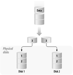 Generally, two-way mirroring is sufficient, but three-way mirrors are useful in some cases, such as providing snapshot data backups without compromising the reliability of the on-line volume. While some implementations allow even more extensive mirroring, it is overkill. Mirroring makes a huge difference in reliability: a two-way mirror of disks with a 1,000,000 hour MTBF per disk has a MTTDL of 5.0 1011 hours! [3]
The performance of a mirrored device is mixed. Writes must be committed to all members, so even best-case write performance is slightly decreased in comparison to a single disk. Most mirroring mechanisms provide two policies for managing mirrored writes :
Read performance of a mirror is substantially different. In terms of single-threaded performance (both random and sequential), the performance is about the same as that of a single member disk. An extremely paranoid implementation might read the data from all member disks and compare, but this is something that is only done in completely fault-tolerant systems. The best case for performance is random-access reads, where the system can pick the least busy disk to satisfy the request, and disk utilization for an N-way mirror is reduced by 1/N. In the event of a mirrored disk failure, the disk must eventually be replaced . The process of bringing a replacement disk up to date is called resynchronization . The most straightforward way to accomplish this update is simply copying all the bits from the surviving disks to the replacement disk. This is exactly what must be done when a full resynchronization is required. Resychronizations are usually performed at a reduced speed (about 1 MB/second/disk) to minimize the impact of the resynchronization on system operation. However, a full resynchronization is not always required; sometimes a submirror is taken offline temporarily -- for example, to conduct a snapshot backup -- in which case only the changed blocks need to be copied . This process is usually accomplished through a dirty region log (DRL), in which a bitmap is provided for each disk. Each bit defines whether a disk region has been changed since the submirror was taken offline. A typical region is 32 KB in size; as a result, the DRL is quite small and its location has a minimal impact on performance. 6.2.3 RAID 2: Hamming Code ArraysOne common mechanism for implementing data corruption detection is a parity code, where the number of ones in a given length of data are counted; the parity bit is 1 if the number of ones is odd and 0 if it is even. A single parity bit can detect an error if any one bit is incorrect, but does not tell which data bit is incorrect. This 1-bit parity scheme is formally called a distance-2 code ; if we look at the data bits, no 1-bit change will result in an identical parity bit being computed. Of course, if we change two bits (either any two data bits or one data bit and the parity bit), the parity matches the data and no error will be detected : there is a distance of two changes between legal combinations of parity and data. If we are interested in detecting more than one error, or in correcting an error, we need a distance-3 code , in which there is a distance of three changes between legal data/parity combinations. [4] This distance will let us correct errors of one bit, and detect but not correct errors of two bits. The number of bits required for a distance-3 code of a given length of data grows slowly compared to the number of bits of data. For example, 64 bits of data require seven parity bits, and 128 bits of data require eight parity bits. This type of encoding is called a Hamming code , after R. Hamming, who described a method of synthesizing this sort of code.
RAID 2 uses this algebraic method to generate the appropriate parity information that allows for data reconstruction in the event of disk failure. However, RAID 2 was never widely deployed due to the complexity of the Hamming code generation algorithms that needed to be implemented in hardware, coupled with restrictions that the algorithms placed on the number and organization of the disks in the array. 6.2.4 RAID 3: Parity-Protected StripingRAID 3 attempts to avoid the problem of poor reliability associated with RAID 0 and the high cost associated with RAID 1. RAID 3 builds upon the idea of striping, but uses an extra disk drive to store a computed parity block. The system computes a parity bit for each bit in the stripe width, and stores the parity data on the corresponding location of the extra disk. It turns out that RAID 3 is extremely difficult to implement technically, because the interlace ranges in size from 1 to 32 bits, and commodity SCSI disks use 512-byte blocks. Most vendors claiming "RAID 3" functionality are actually using RAID 5 arrangements, but with all parity data stored in a single disk. Because RAID 3 is based on the RAID 0 structure, it has a lot of similar benefits: very good performance with operations of sufficient size, and poor performance with small operations (those that only span two disks). While the parity computation itself does not impose a significant (>5%) performance penalty, all writes must involve the parity disk. In read activity, in which parity is not involved, the system performs about as well as RAID 0. The same is true in single-threaded write environments. However, multi-threaded writes start to cause serious problems, because the disk used for parity becomes overloaded; multi-threaded writes to a RAID 3 volume are very similar to that of a single disk. In some environments, this is acceptable. For most multipurpose servers, RAID 3 is not a good choice. RAID 3 is aimed toward optimizing requests that involve all the devices in the array. Since each request to a RAID 3 volume must wait for all the physical subsidiary requests to complete, forcing all the member disks to be in exactly the same position reduces latency problems. This is called spindle synchronization , and works very well for optimizing sequential single-threaded requests. It is a nightmare for random-access performance: it behaves as one very large, very safe disk drive, with the random request rate for the volume the same as the request rate for a given member disk. For all these reasons, RAID 3 is essentially never used. 6.2.5 RAID 4: Parity-Protected Striping with Independent DisksRAID 4 is an expansion on RAID 3; instead of using small chunk sizes, it picks sizes closer to those found in RAID 0 (between 2 and 128 KB). It also does not require the member drives to be spindle synchronized, making RAID 4 much easier to implement using commodity SCSI disks; virtually all devices advertised as "RAID 3" are actually implemented as RAID 4 devices for exactly this reason. RAID 4 has essentially the same strengths and weaknesses as RAID 3; it excels at sequential throughput and reads, but write performance is as slow as a single member disk. 6.2.6 RAID 5: Distributed, Parity-Protected StripingThe weakness of the RAID 3 design philosophy is that it does not adequately solve the problems posed by multitasking environments. RAID 5 addresses this problem by intermixing parity data with actual data in the stripe width, rather than dedicating a single disk or pieces of multiple disks to parity data (see Figure 6-3). Figure 6-3. RAID 5 array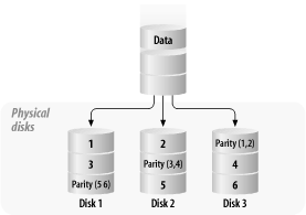 One of the core truths in all parity-based RAID organizations is that they convert logical writes into multiple physical writes. In order to maintain data integrity, these writes must be committed atomically -- otherwise , the computed parity data and the actual data could get out of synchronization, corrupting data. The most common solution to this problem is implementing a two-phase commit process. When a write request is issued, a parity block is computed and written to a buffer area. A log is updated, indicating that a write is pending against the data. Once the data is safely placed in nonvolatile storage, the array management software writes the updated data and parity onto the member disks, and updates the log to reflect a clean status for those blocks. If any part of this process is interrupted , the array management software can restore the volume to a consistent state. This log is written to frequently, but pending writes tend to stay around for only a few milliseconds , so the log is very short. RAID 5 performance is widely misunderstood, particularly for writes. Let's look at the simpler read case first. A single-threaded read to a RAID 5 array is almost as fast as a stripe with one fewer disk; for example, a six-disk RAID 5 array is as fast as a five-disk RAID 0 array. This is because one disk equivalent is held over for parity data in RAID 5. Maximum performance is achieved when the request is aligned on a stripe boundary and the request size is an integer multiple of the data width of the stripe. Multithreaded reads (that is, multiple concurrent reads) from RAID 5 volumes are faster than those on RAID 0 volumes; the additional disk involved in the RAID 5 array distributes the utilization over more drives. As with RAID 0 and RAID 3, performance is at a minimum when the request size is very small and spans two member disks -- this involves activating three disks (two data disk and a parity disk). Unfortunately, write performance is complicated. The first problem is that the write typically involves a read-modify-write cycle. The rest of the data in the stripe (the parity context ) must be read in order to compute the parity data. The new data is then inserted and the data and parity are written back to disk. This gives rise to three situations:
Unfortunately, this situation is even more complex in real life. Because of the necessity for safe two-phase writes, we incur three additional writes: two to update dirty region logs and one to write the updated data and parity. Even worse , the log and data writes must be written in a precise sequential order. RAID 5 is complex, and deciding precisely how to configure such an array can be difficult. The most important strategy is to try and arrange for as many full-stripe writes as possible. If your application is dominated by a particular write transaction, design the array to fit those sizes. This is best accomplished by setting the data width of the volume to be equal to the typical I/O size. If the typical I/O size is 128 KB, and the RAID 5 array has six disks, the chunk size should be 26 KB: RAID 5's real weakness is write performance, especially on small files. This becomes painfully apparent if you are using a RAID 5 volume that is incurring many writes over NFS V2, because of the small I/O sizes allowed by NFS V2. We'll talk about this in greater detail in Section 7.5. When the array has suffered a failure, the performance characteristics change substantially. Under normal operating characteristics, not all disks need to be read, and no reads ever involve a parity computation. When a disk has failed, however, the only way to retrieve data is to read all the member disks and use the parity mechanism (described in Section 6.2 earlier in this chapter) to determine the missing piece of data. When a RAID 5 array is running in a degraded state, a single disk read requires 2 (n-1)/n reads, as opposed to just n reads in fully operational mode, and per-disk utilization approximately doubles. The good news is that write performance is not significantly affected. 6.2.7 RAID 10: Mirrored StripingSimple RAID 1 arrays are now quite unusual, because storage requirements have outgrown single physical disk sizes; as a result, it is now commonplace to create mirrors whose submirrors are stripes. These are often called RAID 10, RAID 1+0, or RAID 0+1 arrays. Figure 6-4 shows RAID 1+0 organization. Figure 6-4. RAID 1+0 organization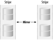 The read performance of a RAID 10 array benefits from both organizations, although random reads benefit only from mirroring when they are multi-threaded. Writes to RAID 10 arrays are typically about 30% slower than those to purely striped volumes, due to the overhead of writing two copies. The order of operations in a RAID 10 array is actually quite important. There are two mechanisms of building such a device with four disks:
Figure 6-5. RAID 0+1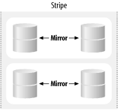 Figure 6-6. RAID 1+0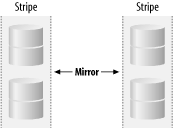 This may seem to be an academic consideration, but the two design philosophies have substantially different behavior when a disk fails. When a RAID 0+1 array suffers a disk failure, an entire submirror is taken offline. Any subsequent failure compromises the entire array. In the RAID 1+0 array, a single disk failure degrades only that component of the stripe: an N-device array can suffer at worst 2 failures, and at best N/2 failures, before data is lost. Unfortunately, vendors are often less than clear as to which sort of design they actually implement. You'll need to check with your vendor to be sure. Solstice DiskSuite is notable in that it forces you to create stripes, then mirror the stripes (RAID 0+1); although this seems wrong, it does actually implement the correct (RAID 1+0) scheme. |
