TCPIP Suite
TCP/IP SuiteAs Chapter 6, "OSI Network Layer," stated, IP does not provide reliable delivery. IP delivers packets on a best-effort basis and provides notification of non-delivery in some situations. This is because not all applications require reliable delivery. Indeed, the nature of some applications suits them to unreliable delivery mechanisms. For example, a network management station (NMS) that must poll thousands of devices using the Simple Network Management Protocol (SNMP) could be heavily burdened by the overhead associated with reliable delivery. Additionally, the affect of dropped SNMP packets is negligible as long as the proportion of drops is low. So, SNMP uses unreliable delivery to promote NMS scalability. However, most applications require reliable delivery. So, the TCP/IP suite places the burden of reliable delivery on the transport layer and provides a choice of transport layer protocols. For unreliable delivery, UDP is used. For reliable delivery, TCP is used. This provides flexibility for applications to choose the transport layer protocol that best meets their delivery requirements. For additional architectural information about the TCP/IP suite, readers are encouraged to consult IETF RFC 1180. UDPWhen packet loss has little or no negative impact on an application, UDP can be used. Broadcast traffic is usually transmitted using UDP encapsulation (for example, DHCPDIS-COVER packets defined in IETF RFC 2131). Some unicast traffic also uses UDP encapsulation. Examples of UDP-based unicast traffic include SNMP commands and DNS queries. UDP Operational OverviewUDP is connectionless. RFC 768 defines UDP, and RFC 1122 defines procedural requirements for UDP. RFC 768 defines the packet format, the packet-level error detection mechanism, and the minimum/maximum packet sizes. UDP leaves all other communication parameters to the upper-layer protocols (ULPs). Thus, UDP adds very little overhead to IP. The only services that UDP provides to ULPs are data-integrity validation (via checksum) and ULP multiplexing. ULP multiplexing is accomplished by assigning a 16-bit identifier (called a port number) to each session layer protocol. Port numbers are conceptually similar to EtherTypes and PPP protocol numbers at the data-link layer, and IP protocol numbers at the network layer. Both UDP and TCP use port numbers to multiplex ULPs. When a port number is assigned to a session layer protocol, it is assigned for use by UDP and TCP. This is done for several reasons. One reason is that some session layer protocols use both UDP and TCP. For example, DNS uses UDP in most situations, but DNS can use TCP to pass through firewalls that block UDP traffic. Another reason is to simplify network management. For example, a session layer protocol that uses UDP today might be modified in the future to use TCP. If that session layer protocol's UDP port number is not reserved for use with TCP, a different session layer protocol could be assigned that TCP port number. This would require assignment of a new port number for the first session layer protocol to use TCP. This complicates firewall configuration, content switching, protocol decoding, and other network management tasks related to that session layer protocol. IANA manages the range of valid port numbers. The range of valid port numbers is 0 to 65,535. It is divided into the following three categories:
Tip The meaning of the term port varies depending on the context. Readers should not confuse the meaning of port in the context of UDP and TCP with the meaning of port in other contexts (such as switching hardware or the SAM addressing scheme). IANA assigns WKPs. WKPs derive their name from their reserved status. Once IANA assigns a port number in the WKP range to a session layer protocol, that port number is reserved for use by only that session layer protocol. Assigned WKPs are used on servers to implement popular services for clients. By reserving port numbers for popular services, clients always know which port number to contact when requesting a service. For example, a server-based implementation of DNS "listens" for incoming client queries on UDP port 53. All unassigned WKPs are reserved by IANA and may not be used. IANA does not assign port numbers outside the WKP range. However, IANA maintains a public register of the server-based port numbers used by session layer protocols that have not been assigned a WKP. These are called Registered Ports. The third category is Dynamic Ports. It is used by clients when communicating with servers. Each session layer protocol within a client dynamically selects a port number in the Dynamic Port range upon initiating communication with a server. This facilitates server-to-client communication for the duration of the session. When the session ends, the Dynamic Port number is released and becomes available for reuse within the client. UDP does not provide data segmentation, reassembly, or reordering for ULPs. So, ULPs that use UDP might suffer performance degradation due to IP fragmentation of large UDP packets. To avoid fragmentation, ULPs that use UDP are required to assess the maximum data segment size that can be transmitted. To facilitate this, UDP transparently provides Session Layer protocols access to the IP service interface. The session layer protocol in the source host queries UDP, which in turn queries IP to determine the local MTU. The session layer protocol then generates packets equal to or less than the local MTU, minus the overhead bytes of the IP and UDP headers. Alternately, path maximum transmission unit (PMTU) discovery can be used. The session layer protocol in the destination host must reorder and reassemble received segments using its own mechanism. UDP Packet FormatsUDP offers a very limited set of services to ULPs, so the UDP packet format does not need to contain many fields. UDP uses a header but does not use a trailer. UDP packets are word-oriented, and an UDP word is 4 bytes. Figure 7-1 illustrates the UDP packet format. Figure 7-1. UDP Packet Format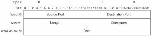 A brief description of each field follows:
For more information about the UDP packet format, readers are encouraged to consult IETF RFCs 768 and 1122. A new variation of UDP (called UDP-Lite) is documented in RFC 3828. UDP-Lite is optimized for streaming media such as voice and video. As such, UDP-Lite is not applicable to modern storage networks. UDP-Lite is mentioned herein only to prevent confusion. UDP Delivery MechanismsUDP supports only one set of delivery mechanisms that provide unacknowledged, connectionless service. Thus, UDP does not augment the delivery service provided by IP. UDP implements the following delivery mechanisms:
For more information about UDP delivery mechanisms, readers are encouraged to consult IETF RFCs 768, 1122, and 1180. UDP Connection InitializationNo UDP parameters are exchanged between hosts before communication. This reflects the connectionless nature of UDP. TCPWhen packet loss affects an application negatively, TCP is used. Most unicast traffic uses TCP encapsulation. TCP Operational OverviewTCP is connection-oriented. Each TCP connection comprises a full-duplex virtual-circuit between a pair of end nodes. Like UDP, TCP provides data integrity validation (via checksum) and ULP multiplexing services (via port numbers). Unlike UDP, TCP provides data segmentation and reordering services, and several end-to-end delivery guarantees to ULPs. RFC 793 defines TCP, whereas RFC 1122 defines procedural requirements for TCP. RFC 793 defines the packet format, minimum and maximum packet sizes, error detection and recovery mechanisms (including a method of packet-loss detection and a procedure for packet retransmission), a flow-control mechanism, connection establishment/maintenance/teardown procedures, a packet reordering mechanism, and timeout values. TCP packetizes and transmits data as TCP sees fit. In other words, data received from a ULP may or may not be sent immediately, and separate transmission requests may or may not be aggregated by TCP. For example, a message-based ULP (such as iSCSI) can pass multiple discrete "chunks" of data to TCP. These data chunks are called Protocol Data Units (PDUs). TCP may aggregate multiple PDUs into a single packet for transmission (subject to PMTU constraints). Likewise, when an ULP passes to TCP a PDU that exceeds the PMTU, TCP may segment and transmit the PDU when and how TCP sees fit. This is known as byte streaming. To TCP, each ULP is the source of a stream of bytes. At the receiving host, TCP does not reassemble segments per se. Because TCP does not segment ULP data as discrete PDUs, TCP cannot reassemble segments into discrete PDUs. So, TCP in a receiving host merely ensures the proper order of received segments before passing data to a ULP. The ULP in the receiving host is responsible for detecting the boundaries between PDUs. Note that TCP in a receiving host may delay passing data to a ULP even when all segments are properly ordered. Sometimes this is done to improve buffer management efficiency. However, a mechanism (the Push bit) is defined to enable ULPs in the transmitting host to instruct TCP in both the transmitting and receiving hosts to immediately forward data (see Chapter 9, "Flow Control and Quality of Service"). In other words, the first PDU received from the ULP may be held by TCP while TCP waits for additional PDUs from the ULP. TCP does not recognize and process data received from a ULP as discrete PDUs. TCP supports an optional keep-alive mechanism to maintain an open connection during periods of inactivity. The keep-alive mechanism is not included in RFC 793, so RFC 1122 addresses the need for a keep-alive mechanism. RFC 1122 requires the inactivity timer to be configurable. So, most modern TCP implementations support an inactivity timer ranging from a few seconds to many hours. Network administrators determine the optimum value for the inactivity timer based on specific deployment requirements. The TCP keep-alive mechanism works by transmitting an invalid packet, which elicits an acknowledgement packet from the peer host. The transmitting host indicates via the Sequence Number field that it is ready to transmit a byte of data that has already been acknowledged by the peer host. The keep-alive packet contains no data. Upon processing the keep-alive packet, the peer host detects the error in the Sequence Number field and retransmits the most recent acknowledgement packet. This two-packet exchange implicitly notifies each host that the connection is still valid. If the connection is no longer valid, the receiving host returns a reset packet to the transmitting host. Multiple simultaneous TCP connections can be open between each pair of hosts. In fact, this is required when multiple ULPs are communicating because ULPs may not share a TCP connection. The combination of a TCP port number and an IP address is called a socket. Each TCP connection is uniquely identified by the pair of communicating sockets. This enables each host to use a single socket to communicate simultaneously with multiple remote sockets without confusing the connections. In the context of traditional IP networks, this is common in server implementations. In the context of storage networks, this is common in storage implementations. For example, an iSCSI target (storage array) may use a single socket to conduct multiple simultaneous sessions with several iSCSI initiators (hosts). The storage array's iSCSI socket is reused over time as new sessions are established. Clients may also reuse sockets. For example, a single-homed host may select TCP port 55,160 to open a TCP connection for file transfer via FTP. Upon completing the file transfer, the client may terminate the TCP connection and reuse TCP port 55,160 for a new TCP connection. Reuse of Dynamic Ports is necessary because the range of Dynamic Ports is finite and would otherwise eventually exhaust. A potential problem arises from reusing sockets. If a client uses a given socket to connect to a given server socket more than once, the first incarnation of the connection cannot be distinguished from the second incarnation. Reincarnated TCP connections can also result from certain types of software crashes. TCP implements multiple mechanisms that work together to resolve the issue of reincarnated TCP connections. Note that each TCP host can open multiple simultaneous connections with a single peer host by selecting a unique Dynamic Port number for each connection. TCP Packet FormatsTCP offers a rich set of services to ULPs, so the TCP packet format is quite complex compared to UDP. TCP uses a header but does not use a trailer. The TCP header format defined in RFC 793 is still in use today, but some fields have been redefined. TCP packets are word-oriented, and a TCP word is 4 bytes. Figure 7-3 illustrates the TCP packet format. Figure 7-3. TCP Packet Format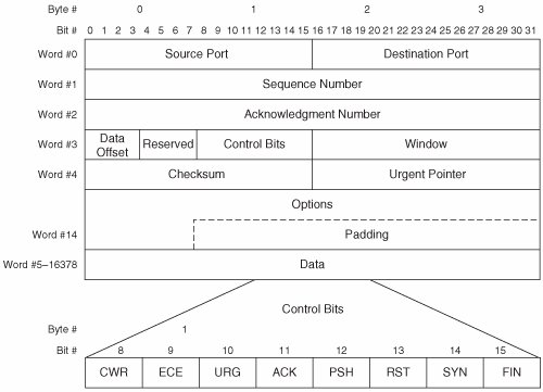 A brief description of each field follows:
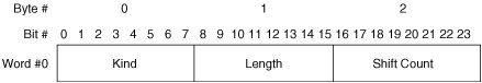
The preceding descriptions of the TCP header fields are simplified for the sake of clarity. For more information about the TCP packet format, readers are encouraged to consult IETF RFCs 793, 1122, 1323, and 3168. TCP OptionsTCP options can be comprised of a single byte or multiple bytes. All multi-byte options use a common format. Figure 7-4 illustrates the format of TCP multi-byte options. Figure 7-4. TCP Multi-Byte Option Format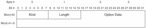 A brief description of each field follows:
Table 7-1 lists the currently defined TCP options that are in widespread use.
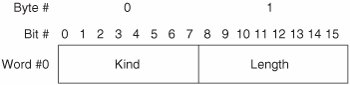
Of the options listed in Table 7-1, only the MSS, WSopt, SACK-Permitted, SACK, and TSopt are relevant to modern storage networks. So, only these options are discussed in detail in this section. Maximum Segment SizeThe maximum segment size (MSS) option is closely related to PMTU discovery. Recall that TCP segments ULP data before packetizing it. MSS refers to the maximum amount of ULP data that TCP can packetize and depacketize. While this could be limited by some aspect of the TCP software implementation, it is usually limited by the theoretical maximum size of the Data field in a TCP packet (65,496 bytes). Each host can advertise its MSS to the peer host during connection establishment to avoid unnecessary segmentation. Note that the MSS option may be sent only during connection establishment, so the advertised MSS value cannot be changed during the life of an open connection. If the theoretical MSS is advertised, the peer host can send TCP packets that each contain up to 65,496 bytes of ULP data. This would result in severe fragmentation of packets at the network layer due to the ubiquity of Ethernet. So, the best current practice (BCP) is to advertise an MSS equal to the local MTU minus 40 bytes (20 bytes for the IP header and 20 bytes for the TCP header). This practice avoids unnecessary fragmentation while simultaneously avoiding unnecessary segmentation. If a host implements PMTU discovery, TCP uses the lesser of the discovered PMTU and the peer's advertised MSS when segmenting ULP data for transmission. Figure 7-5 illustrates the MSS option format. Figure 7-5. TCP Maximum Segment Size Option Format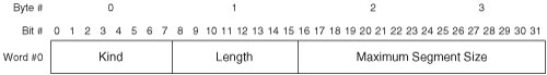 A brief description of each field follows:
Window ScaleOne drawback of all proactive flow control mechanisms is that they limit throughput based on the amount of available receive buffers. As previously stated, a host may not transmit when the receiving host is out of buffers. To understand the effect of this requirement on throughput, it helps to consider a host that has enough buffer memory to receive only one packet. The transmitting host must wait for an indication that each transmitted packet has been processed before transmitting an additional packet. This requires one round-trip per transmitted packet. While the transmitting host is waiting for an indication that the receive buffer is available, it cannot transmit additional packets, and the available bandwidth is unused. So, the amount of buffer memory required to sustain maximum throughput can be calculated as:
where bandwidth is expressed in bytes per second, and RTT is expressed in seconds. This is known as the bandwidth-delay product. Although this simple equation does not account for the protocol overhead of lower-layer protocols, it does provide a reasonably accurate estimate of the TCP memory requirement to maximize throughput. As TCP/IP matured and became widely deployed, the maximum window size that could be advertised via the Window field proved to be inadequate in some environments. So-called long fat networks (LFNs), which combine very long distance with high bandwidth, became common as the Internet and corporate intranets grew. LFNs often exceed the original design parameters of TCP, so a method of increasing the maximum window size is needed. The Window Scale option (WSopt) was developed to resolve this issue. WSopt works by shifting the bit positions in the Window field to omit the least significant bit(s). To derive the peer host's correct window size, each host applies a multiplier to the window size advertisement in each packet received from the peer host. Figure 7-6 illustrates the WSopt format. Figure 7-6. TCP Window Scale Option Format A brief description of each field follows:
Both hosts must send WSopt for window scaling to be enabled on a connection. Sending this option indicates that the sender can both send and receive scaled Window fields. Note that WSopt may be sent only during connection establishment, so window scaling cannot be enabled during the life of an open connection. Selective AcknowledgementTCP's cumulative acknowledgement mechanism has limitations that affect performance negatively. As a result, an optional selective acknowledgement mechanism was developed. The principal drawback of TCP's cumulative acknowledgement mechanism is that only contiguous data bytes can be acknowledged. If multiple packets containing non-contiguous data bytes are received, the non-contiguous data is buffered until the lowest gap is filled by subsequently received packets. However, the receiving host can acknowledge only the highest sequence number of the received contiguous bytes. So, the transmitting host must wait for the retransmit timer to expire before retransmitting the unacknowledged bytes. At that time, the transmitting host retransmits all unacknowledged bytes for which the retransmit timer has expired. This often results in unnecessary retransmission of some bytes that were successfully received at the destination. Also, when multiple packets are dropped, this procedure can require multiple roundtrips to fill all the gaps in the receiving host's buffer. To resolve these deficiencies, TCP's optional SACK mechanism enables a receiving host to acknowledge receipt of non-contiguous data bytes. This enables the transmitting host to retransmit multiple packets at once, with each containing non-contiguous data needed to fill the gaps in the receiving host's buffer. By precluding the wait for the retransmit timer to expire, retransmitting only the missing data, and eliminating multiple roundtrips from the recovery procedure, throughput is maximized. SACK is implemented via two TCP options. The first option is called SACK-Permitted and may be sent only during connection establishment. The SACK-Permitted option informs the peer host that SACK is supported by the transmitting host. To enable SACK, both hosts must include this option in the initial packets transmitted during connection establishment. Figure 7-7 illustrates the format of the SACK-Permitted option. Figure 7-7. TCP SACK-Permitted Option Format A brief description of each field follows:
After the connection is established, the second option may be used. The second option is called the SACK option. It contains information about the data that has been received. Figure 7-8 illustrates the format of the SACK option. Figure 7-8. TCP SACK Option Format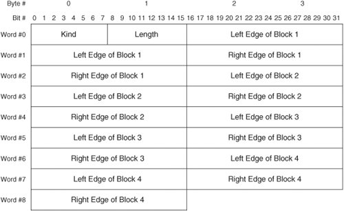 A brief description of each field follows:
TCP's SACK mechanism complements TCP's cumulative ACK mechanism. When the lowest gap in the receive buffer has been filled, the receiving host updates the Acknowledgement Number field in the next packet transmitted. Note that TCP's SACK mechanism provides an explicit ACK for received data bytes currently in the receive buffer, and an explicit NACK for data bytes currently missing from the receive buffer. This contrasts TCP's cumulative ACK mechanism, which provides an implicit ACK for all received data bytes while providing an implicit NACK for all missing data bytes except the byte referenced in the Acknowledgement Number field. Note also the difference in granularity between the retransmission procedures of TCP and FC. Whereas TCP supports retransmission of individual packets, the finest granularity of retransmission in FC is a sequence. TimestampsThe Timestamps option (TSopt) provides two functions. TSopt augments TCP's traditional duplicate packet detection mechanism and improves TCP's RTT estimation in LFN environments. TSopt may be sent during connection establishment to inform the peer host that timestamps are supported. If TSopt is received during connection establishment, timestamps may be sent in subsequent packets on that connection. Both hosts must support TSopt for timestamps to be used on a connection. As previously stated, a TCP connection may be reincarnated. Reliable detection of duplicate packets can be challenging in the presence of reincarnated TCP connections. TSopt provides a way to detect duplicates from previous incarnations of a TCP connection. This topic is discussed fully in the following section on duplicate detection. TCP implements a retransmission timer so that unacknowledged data can be retransmitted within a useful timeframe. When the timer expires, a retransmission time-out (RTO) occurs, and the unacknowledged data is retransmitted. The length of the retransmission timer is derived from the mean RTT. If the RTT is estimated too high, retransmissions are delayed. If the RTT is estimated too low, unnecessary retransmissions occur. The traditional method of gauging the RTT is to time one packet per window of transmitted data. This method works well for small windows (that is, for short distance and low bandwidth), but severely inaccurate RTT estimates can result from this method in LFN environments. To accurately measure the RTT, TSopt may be sent in every packet. This enables TCP to make real-time adjustments to the retransmission timer based on changing conditions within the network (such as fluctuating levels of congestion, route changes, and so on). Figure 7-9 illustrates the TSopt format. Figure 7-9. TCP Timestamps Option Format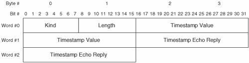 A brief description of each field follows:
The preceding descriptions of the TCP options are simplified for the sake of clarity. For more information about the TCP option formats, readers are encouraged to consult IETF RFCs 793, 1122, 1323, 2018, 2385, and 2883. TCP Delivery MechanismsTCP supports only one set of delivery mechanisms that provide acknowledged, connection-oriented service. Thus, TCP augments the delivery service provided by IP. TCP implements the following delivery mechanisms:
Comprehensive exploration of all the TCP delivery mechanisms is outside the scope of this book. For more information about TCP delivery mechanisms, readers are encouraged to consult IETF RFCs 793, 896, 1122, 1180, 1191, 1323, 2018, 2309, 2525, 2581, 2873, 2883, 2914, 2923, 2988, 3042, 3168, 3390, 3517, and 3782. TCP Connection InitializationTCP connections are governed by a state machine. As each new connection is initialized, TCP proceeds through several states. A TCP client begins in the CLOSED state and then proceeds to the SYN-SENT state followed by the ESTABLISHED state. A TCP server begins in the LISTEN state and then proceeds to the SYN-RECEIVED state followed by the ESTABLISHED state. ULP data may be exchanged only while a connection is in the ESTABLISHED state. When the ULP has no more data to transmit, TCP terminates the connection. TCP proceeds through several additional states as each connection is terminated. The state of each connection is maintained in a small area in memory called a transmission control block (TCB). A separate TCB is created for each TCP connection. RFC 793 defines procedures for establishment, maintenance and teardown of connections between pairs of hosts. Following IP initialization, TCP may initiate a new connection. TCP's connection initialization procedure is often called a three-way handshake because it requires transmission of three packets between the communicating hosts. The initiating host selects an initial sequence number (ISN) for the new connection and then transmits the first packet with the SYN bit set to 1 and the ACK bit set to 0. This packet is called the SYN segment. If the initiating host supports any TCP options, the options are included in the SYN segment. Upon receipt of the SYN segment, the responding host selects an ISN for the new connection and then transmits a reply with both the SYN and ACK bits set to one. This packet is called the SYN/ACK segment. If the responding host supports any TCP options, the options are included in the SYN/ACK segment. The Acknowledgement Number field contains the initiating host's ISN incremented by one. Upon receipt of the SYN/ACK segment, the initiating host considers the connection established. The initiating host then transmits a reply with the SYN bit set to 0 and the ACK bit set to 1. This is called an ACK segment. (Note that ACK segments occur throughout the life of a connection, whereas the SYN segment and the SYN/ACK segment only occur during connection establishment.) The Acknowledgement Number field contains the responding host's ISN incremented by one. Despite the absence of data, the Sequence Number field contains the initiating host's ISN incremented by one. The ISN must be incremented by one because the sole purpose of the ISN is to synchronize the data byte counter in the responding host's TCB with the data byte counter in the initiating host's TCB. So, the ISN may be used only in the first packet transmitted in each direction. Upon receipt of the ACK segment, the responding host considers the connection established. At this point, both hosts may transmit ULP data. The first byte of ULP data sent by each host is identified by incrementing the ISN by one. Figure 7-10 illustrates TCP's three-way handshake. Figure 7-10. TCP Three-Way Handshake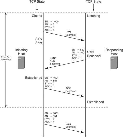 |
EAN: 2147483647
Pages: 196