Internet Protocol
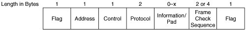
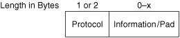
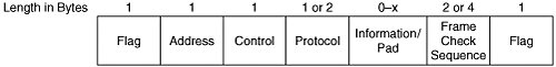
| IP is the most ubiquitous network layer protocol in the world. IP's robust support of data-link layer technologies, ability to service multiple transport layer protocols, and functional extensibility have contributed largely to its success. Leveraging IP to transport Small Computer System Interface (SCSI) was inevitable once SCSI was adapted to serial networking technologies. IPv4 OverviewIP is an open protocol that facilitates network layer communication across internetworks in a packet-switched manner. One or more of the underlying data-link layer networks may operate in a circuit-switched manner, but IP operation at the network layer remains packet-switched. IP provides just the functionality required to deliver packets from a source device to a destination device. Even path determination is left to other network layer protocols called routing protocols (see Chapter 10, "Routing and Switching Protocols"). Thus, IP is a routed protocol. Likewise, IP relies on other network layer protocols for data confidentiality (see the IPsec section of Chapter 12, "Storage Network Security") and control messaging (see the ICMP section of this chapter). IPv4 is currently the most widely deployed version of IP. A newer version has been developed (IPv6), but it is not yet widely deployed. IP version numbers are somewhat misleading. The IP header contains a field that identifies the protocol version number. Valid values are 0 through 15. Version numbers 0 and 1 were once assigned to the first and second revisions of a protocol that combined transport layer and network layer functionality. With the third revision, the combined protocol was separated into TCP and IP. That revision of IP was assigned the next available version number (2). Two more revisions of IP were produced and assigned version numbers 3 and 4. When the next revision of IP was produced, it was decided that the version numbers should be reassigned. Version 4 was reassigned to the latest revision of IP, which was the fourth revision of IP as an independent protocol. That revision is now commonly called IPv4. Version number 0 was reserved for intuitive reasons. Version numbers 1 through 3 were left unassigned. Note the first three independent revisions of IP were unstable and never adopted. Because the original two revisions of IP were actually a combined protocol, those revisions were not considered during version-number reassignment. Thus, IPv4 is really the first version of IP ever deployed as a standard protocol. IPv4 originally was adopted via RFC 760. IPv4 has since been revised, but the protocol version number has not been incremented. Instead, the RFC numbering system is used to identify the current revision of IPv4. RFC 791 is the current revision of IPv4. Subsequent to IPv4 adoption, a completely different network layer protocol was developed by IETF and assigned protocol version number 5. When development of the next generation of IP was undertaken, the new protocol was assigned version number 6 (IPv6). Thus, IPv6 is really the second version of IP ever deployed as a standard protocol. IPv6 was revised multiple times before adoption and one time since adoption, but the protocol version number has not been incremented. Like IPv4, the current revision of IPv6 is tracked via RFC numbers. Originally adopted via RFC 1883, the current revision of IPv6 is RFC 2460. Development of IPv6 was motivated primarily by the need to expand the address space of IPv4. To extend the life of IPv4 during development of IPv6, new techniques were developed to improve the efficiency of address consumption. Chief among these techniques are private addressing, Network Address Translation (NAT), and variable-length subnet masking (VLSM). These techniques have been so successful that they have significantly slowed adoption of IPv6. Because IPv6 is not yet used in storage networks, the remainder of this book focuses on IPv4 when discussing IP. When discussing IP, it is customary to use the term interface rather than port. The purpose is to distinguish between the network layer functionality (the interface) and the data-link layer functionality (the port) in an IP-enabled device. For example, an Ethernet switch can contain a logical IP interface that is used for management access via any Ethernet port. We use customary IP terminology in this chapter when discussing switches or routers because SAM terminology does not apply to networking devices. Networking devices do not implement SCSI; they merely forward encapsulated SCSI packets. However, we use SAM terminology in this chapter when discussing end nodes, to maintain consistency with previous chapters. In the SAM context, an IP interface is a logical SAM port associated with a physical SAM port (such as Ethernet). We discuss this topic in detail in the addressing scheme section of this chapter. The line between end nodes and networking devices is becoming fuzzy as hybrid devices enter the storage market. Hybrid devices implement SCSI but are installed in networking devices. For example, Cisco Systems produces a variety of storage virtualization modules that are deployed in the MDS9000 family of switches. These virtualization modules should be viewed as end nodes, whereas the MDS9000 switches should be viewed as networking devices. Further discussion of hybrid devices is outside the scope of this book, but readers should be aware of the distinction made herein to avoid confusion when planning the deployment of hybrid devices. Another difference in terminology between data-link layer technologies and network layer technologies arises in the context of flow control and QoS. The term buffer is typically used when discussing data-link layer technologies, whereas the term queue is typically used when discussing network layer technologies. A buffer and a queue are essentially the same thing. That said, network layer technologies implement queue management policies that are far more sophisticated than data-link layer buffer management policies. For additional architectural information about the TCP/IP suite, readers are encouraged to consult IETF RFC 1180. Data-Link SupportOne of the most beneficial features of IP is its ability to operate on a very broad range of data-link layer technologies. The IETF is very diligent in adapting IP to new data-link layer technologies as they emerge. Of the many data link layer technologies supported, the most commonly deployed are Ethernet, PPP, high-level data-link control (HDLC), frame relay, asynchronous transfer mode (ATM), and multiprotocol label switching (MPLS). Most Internet Small Computer System Interface (iSCSI) deployments currently employ Ethernet end-to-end. Because Fibre Channel over TCP/IP (FCIP) is a point-to-point technology, most current deployments employ PPP over time-division multiplexing (TDM) circuits for WAN connectivity. Though Internet Fibre Channel Protocol (iFCP) supports mesh topologies, most deployments are currently configured as point-to-point connections that employ PPP over TDM circuits for WAN connectivity. Thus, we discuss only Ethernet and PPP in this section. EthernetAs discussed in Chapter 3, "Overview of Network Operating Principles," an Ethertype value is assigned to each protocol carried by Ethernet. Before the IEEE became the official authority for Ethertype assignments, Xerox Corporation fulfilled the role. Xerox assigned Ethertype 0x0800 to IP. When the IEEE took control, they listed many of the Ethertype values as assigned to Xerox. To this day, the IEEE listing of Ethertype assignments still shows 0x0800 assigned to Xerox. However, RFC 894 documents Ethertype 0x0800 as assigned to IP, and the public at large accepts RFC 894 as the final word on this issue. IANA maintains an unofficial listing of Ethertype assignments that properly shows 0x0800 assigned to IP. As discussed in Chapter 5, "OSI Physical and Data-Link Layers," Address Resolution Protocol (ARP) is used to resolve IP addresses to Ethernet addresses. Xerox assigned Ethertype 0x0806 to ARP, but this is not documented via RFC 894, and the IEEE Ethertype listing shows Xerox as the assignee for this value. The unofficial IANA listing of Ethertype assignments properly shows 0x0806 assigned to ARP. The Ethernet padding mechanism discussed in Chapter 5, "OSI Physical and Data-Link Layers," is sometimes used for IP packets. The minimum size of an Ethernet frame is 64 bytes, but the 802.3-2002 header and trailer are only 18 bytes. The IP header (without options) is only 20 bytes, and there is no minimum length requirement for the payload of an IP packet. Some upper-layer protocols (ULPs) can generate IP packets with payloads less than 26 bytes. Examples include TCP during connection establishment and many ICMP messages. When this occurs, the minimum Ethernet frame length requirement is not met. So, Ethernet inserts padding when the IP packet is framed for transmission. The Ethernet padding is not part of the IP packet, so it does not affect any fields in the IP header. PPPIn the early 1970s, IBM invented the Synchronous Data Link Control (SDLC) protocol to facilitate mainframe-to-peripheral communication. SDLC proved to be very effective, but it could not be used by open systems. So, IBM submitted SDLC to the ISO. In 1979, the ISO developed the HDLC protocol, which used SDLC's frame format, but differed from SDLC in operation. Like all protocols, HDLC has limitations. One of HDLC's limitations is lack of support for multiple ULPs. To address this and other shortcomings, the IETF developed PPP in 1989 based on HDLC. The original PPP frame format was derived from HDLC but was modified to support multiple ULPs. Each ULP is identified using an IANA-assigned 16-bit protocol number. The protocol number for IPv4 is 0x0021. PPP also enhances HDLC operationally in several ways. The most recent version of PPP is RFC 1661. PPP is used on serial, point-to-point circuits that inherently provide in-order delivery. Modern storage networks that employ PPP typically do so on DS-1, DS-3, and Synchronous Optical Network (SONET) circuits. PPP consists of three components: a frame format definition, the Link Control Protocol (LCP), and a suite of Network Control Protocols (NCPs). The standard frame format can be used by all ULPs, or deviations from the standard frame format can be negotiated during connection establishment via LCP. LCP is also used to open and close connections, negotiate the MTU (can be symmetric or asymmetric), authenticate peer nodes, test link integrity, and detect configuration errors. Each ULP has its own NCP. An NCP is responsible for negotiating and configuring ULP operating parameters. The NCP for IP is called the IP Control Protocol (IPCP). IPCP was first defined in RFC 1134, which is the original PPP RFC. IPCP was later separated into its own RFC. The most recent version of IPCP is defined in RFC 1332. The PPP protocol number for IPCP is 0x8021. IPCP currently negotiates only four configuration parameters: header compression, IP address assignment, name server assignment, and mobility. Header compression on PPP links is designed for low-speed circuits used for dialup connectivity. Header compression is rarely used on high-speed circuits such as DS-1 and above. IP address assignment, name-server assignment, and mobility are designed for end nodes that require remote access to a network. None of these options apply to FCIP or iFCP deployments. The original PPP frame format is shown in Figure 6-1. Figure 6-1. Original PPP Frame Format The original PPP frame format has since been modified as shown in Figure 6-2. Figure 6-2. Current PPP Frame Format The new frame format allows PPP to be encapsulated easily within a wide variety of other data-link layer frames. This enables multi-protocol support in data-link layer technologies that do not natively support multiple ULPs. The new frame format also allows the leading byte of the protocol number to be omitted if the value is 0x00, which improves protocol efficiency. This improvement applies to IP. When PPP is used on DS-1, DS-3, and SONET circuits, HDLC framing is used to encapsulate the PPP frames. This is called PPP in HDLC-like Framing and is documented in RFC 1662. Some additional requirements apply to PPP when operating on SONET circuits, as documented in RFC 2615 and RFC 3255. Figure 6-3 illustrates PPP in HDLC-like Framing. Figure 6-3. PPP in HDLC-Like Framing A brief description of each field follows:
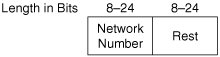
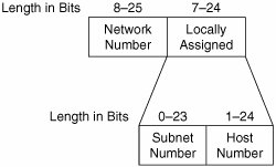
Addressing SchemeIP does not implement an equivalent to SAM device or port names. However, IP does implement a naming mechanism that provides similar functionality to SAM port names under certain circumstances. The primary objective of the Domain Name System (DNS) is to allow a human-friendly name to be optionally assigned to each IP address. Doing so allows humans to use the DNS name of a port or interface instead of the IP address assigned to the port or interface. For example, DNS names usually are specified in web browsers rather than IP addresses. Even though this is a major benefit, it is not the function that SAM port names provide. Another benefit is that DNS names facilitate persistent identification of ports in the context of dynamically assigned IP addresses. This is accomplished by statically assigning a name to each port within the host operating system, then dynamically registering each port name in DNS along with the IP address dynamically assigned to the port during the boot process. Each time a new IP address is assigned, the port name is re-registered. This permits a single DNS name to persistently identify a port, which is the function that SAM port names provide. However, DNS names are assigned to IP addresses rather than to ports, and IP addresses are routinely reassigned among many ports. Additionally, DNS name assignments are not guaranteed to be permanent. For example, it is possible to change the DNS name of an IP address that is assigned to a port and to reassign the old DNS name to a different IP address that is assigned to a different port. After doing so, the old DNS name no longer identifies the original port. Thus, the SAM port-name objective is not met. The primary purpose of a SAM port name is to positively and persistently identify a single port; therefore each name must be permanently assigned to a single port. It is also possible for a port to be assigned multiple IP addresses. Because each IP address is assigned its own DNS name, multiple DNS names can identify a single port. All these factors illustrate why DNS names are not analogous to SAM port names. Likewise, DNS names are not analogous to SAM device names. Each host is assigned a host name in its operating system. The host name represents the host chassis and everything contained within it. Host names can be extended to DNS by using the host name as the DNS name of an IP address assigned to the host. That DNS name then represents the host chassis and everything contained within it. As such, that DNS name represents a superset of a SAM device name. Even when a DNS name represents just an IP address (not a host name) on a single-port interface with only one IP address, the DNS name is not analogous to a SAM device name. Because the primary purpose of a SAM device name is to positively and persistently identify a single interface (network interface card [NIC] or host bus adapter [HBA]), each name must be permanently assigned to a single interface. As outlined in the previous paragraph, DNS names do not comply with this requirement. IP implements the equivalent of SAM port identifiers via IP addresses, which are used to forward packets. In the context of IP storage (IPS) protocols, a node's IP address and data-link layer address both provide SAM port identifier functionality. An IP address facilitates end-to-end forwarding of packets, and a data-link layer address facilitates forwarding of frames between IP interfaces and ports across a single link (in the case of PPP) or multiple links (in the case of Ethernet). The IPv4 address format is very flexible and well documented in many books, white papers, product manuals, and RFCs. So this section provides only a brief review of the IPv4 address format for readers who do not have a strong networking background. To understand the current IPv4 address format, first it is useful to understand the IPv4 address format used in early implementations. Figure 6-4 illustrates the IPv4 address format used in early implementations as defined in RFC 791. Figure 6-4. Early IPv4 Address Format A brief description of each field follows:
This addressing scheme was called "classful" because the interpretation of addresses was determined by the network class. Network numbers were assigned by IANA to companies, government agencies, and other organizations as requested. As the assignment of network numbers continued, the Internet grew, and the limitations of classful addressing and routing were discovered. The primary concerns were the difficulty of scaling flat networks, the rate of address consumption, and degraded router performance. Organizations that had been assigned class A or B network numbers were struggling to scale their flat networks because of the effect of broadcast traffic. The finite supply of network numbers began to dwindle at an unforeseen pace, which raised concerns about future growth potential. Routing between organizations (a process called inter-domain routing) became problematic because route lookups and protocol convergence required more time to complete as routing tables grew. To resolve these issues, several changes were made to the addressing scheme, address allocation procedures, and routing processes. One of the changes introduced was a method of segregating large networks into smaller networks called subnetworks or subnets. Subnetting limited the effect of broadcast traffic by creating multiple broadcast domains within each classful network. Before subnetting, each classful network represented a single IP broadcast domain. Class A and B networks experienced severe host and network performance degradation as the number of host attachments increased because
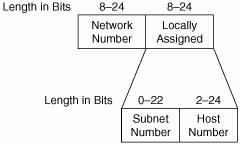
Another challenge resulted from data-link layer limitations. The most popular LAN technologies severely limited the number of hosts that could be attached to each segment. To accommodate the number of IP addresses available in class A and B networks, multiple LAN segments had to be bridged together. Disparate LAN technologies were often used, which created bridging challenges. Subnetting mitigated the need for bridging by enabling routers to connect the disparate LAN technologies. Subnetting is accomplished via a masking technique. The subnet mask indicates the number of bits in the IPv4 address that make up the subnet address within each classful network. Subnet masking provides IP routers with a new way to determine the correct number of bits to inspect when making forwarding decisions. Initially, the subnet mask used within each classful network was fixed-length as described in RFC 950. In other words, a classful network could be subdivided into two subnets of equal size, or four subnets of equal size, or eight subnets of equal size, and so on. Figure 6-5 illustrates the subnetted classful IPv4 address format. Note that the total length of the address remained 4 bytes. Figure 6-5. Subnetted Classful IPv4 Address Format Fixed-length subnetting improved matters, but eventually proved to be less efficient than desired. So, the subnet masking technique was enhanced via RFC 1009 to allow variable-length masks. The new technique is called variable length subnet masking (VLSM). It permits extreme granularity in the allocation of subnets within a network. VLSM resolves the issues associated with scaling flat networks, but only partially resolves the issue of address consumption. So, RFC 1174 and RFC 1466 changed the way network numbers are assigned. Additionally, a method for translating addresses was defined in RFC 1631 (later updated by RFC 3022), and specific network numbers were reserved for "private" use via RFC 1918. To complement these changes, the concept of address masking was extended to the network portion of the IPv4 address format via RFC 1338. This technique was originally called supernetting, but was later renamed classless inter-domain routing (CIDR) in RFC 1519. CIDR resolves the issues associated with degraded router performance by aggregating multiple contiguous network routes into a summary route. CIDR-enabled routers provide the same functionality as classful routers, but CIDR-enabled routers contain far fewer routes in their routing tables. Eventually, CIDR replaced classful addressing and routing. Today, IP addresses are called "classless" because the historically reserved network number ranges in the first byte no longer have meaning. When an organization is assigned a network number, it is also assigned a network prefix. A network prefix is conceptually similar to a subnet mask, but it indicates the number of bits that make up the network number as opposed to the number of bits that make up the network and subnet numbers. Prefix granularity is achieved by supporting 1-bit increments. CIDR complements VLSM; an organization may subnet its network if needed. Figure 6-6 illustrates the classless IPv4 address format. Note that the total length of the address is still 4 bytes. Figure 6-6. Classless IPv4 Address Format A brief description of each field follows:
IPv4 addresses are expressed in dotted decimal notation such as 172.45.9.36. A network prefix also can be expressed in dotted decimal notation, but it is called a network mask or netmask when expressed in this notation. The valid decimal values of a netmask are limited to a specific set of numbers that includes 0, 128, 192, 224, 240, 248, 252, 254, and 255. This results from the convention of masking network numbers in a bit-contiguous manner. In other words, the bits that make up a network number are always the leftmost contiguous bits of an IPv4 address. For example, the network number 172.45.8 is expressed as 172.45.8.0 netmask 255.255.248.0. All bit positions in the netmask that are set to 1 represent network number bit positions in the IPv4 address. Thus, 172.45.9.0 netmask 255.255.255.0 indicates the network number 172.45.9. Alternatively, 172.45.9.36 netmask 255.255.248.0 indicates IP address 172.45.9.36 within the 172.45.8 network. In the CIDR context, network prefixes are expressed as /nn where nn equals the number of leftmost contiguous bits in the IPv4 address that compose the network number. For example, 172.45.8.0/21 is the network prefix notation equivalent to 172.45.8.0 netmask 255.255.248.0. If subnetting is used within a network, the netmask and network prefix must be increased by the assignee organization to include the subnet bits within the Locally Assigned field of the IPv4 address. An extended netmask is called a subnet mask. Likewise, an extended network prefix is called a subnet prefix. To clarify the concepts introduced in this paragraph, Table 6-1 presents an example of dotted decimal notation with equivalent dotted binary notation.
The preceding discussion of the IPv4 addressing scheme is highly simplified for the sake of brevity. Comprehensive exploration of the IPv4 addressing scheme is outside the scope of this book. For more information, readers are encouraged to consult IETF RFCs 791, 950, 1009, 1174, 1338, 1466, 1517, 1519, 1520, 1918, and 3022. Name Assignment and ResolutionBecause IP does not implement SAM device or port names, IP does not need SAM name assignment and resolution mechanisms. Each of the IPS protocols is responsible for implementing its own SAM device and port names (if required). Likewise, each of the IPS protocols is responsible for implementing its own SAM name assignment and resolution mechanisms (if required). Alternately, an external protocol may be leveraged for SAM name assignment and resolution. Chapter 8, "OSI Session, Presentation, and Application Layers," discusses the IPS protocols in detail. As previously mentioned, DNS does not relate to SAM names. However, DNS is an integral component of every IP network, so network administrators undertaking IPS protocol deployment should have a basic understanding of DNS semantics and mechanics. Even though it is possible for system administrators to create static name-to-address mappings in the HOST table on each host, this is typically done only in special situations to accomplish a particular goal. Most name resolution is accomplished dynamically via DNS. DNS employs a hierarchical name space. Except for the lowest level, each level in the hierarchy corresponds to an administrative domain or sub-domain. The lowest level corresponds to individual nodes within a domain or sub-domain. The hierarchy appears as an inverted tree when diagrammed. The root is represented by the "." symbol. The "." symbol also follows the name of each level to signify the boundary between levels. For example, the DNS name "www.cisco.com." indicates the host port named "www" exists in the ".cisco" domain, which exists in the ".com" domain, which exists in the root domain. Note that the "." symbol does not precede "www", which indicates that "www" is a leaf (that is, an end node) in the DNS tree. In practice, the root symbol is omitted because all top-level domains (TLDs) inherently exist under the root, and TLD names are easily recognizable. The most common TLD names are .com, .net, .org, .edu, .gov, and .mil, but others are defined. TLDs are tightly restricted by IANA. The "." symbol is also omitted when referring to the name of an individual level in the hierarchy. For example, "www" exists in the "cisco" domain. Such name references are called unqualified names. A fully qualified domain name (FQDN) includes the full path from leaf to root such as "www.cisco.com". DNS was designed to be extensible. DNS is used primarily to resolve names to IP addresses, but DNS can be used for other purposes. Each datum associated with a name is tagged to indicate the type of datum. New tags can be defined to extend the functionality of DNS. Indeed, many new tags have been defined since the inception of DNS. The DNS database is too large for the entire Internet to be served by a single DNS server. So, the DNS database is designed to be distributed. Each organization is responsible for and has authority over its own domain and sub-domains. This enables the overhead of creating and deleting DNS records to be distributed among all DNS participants. Each organization's DNS servers are authoritative for that organization's domain. As needed, each DNS server retrieves and temporarily caches foreign records from the authoritative DNS servers of foreign domains. This minimizes server memory requirements and network bandwidth requirements. When a DNS client queries the DNS, the query is usually sent to the topologically nearest DNS server. If a client queries a name that does not exist in the local domain (that is, the domain over which the local server has authority), then the local server queries the authoritative server of the domain directly above the local domain in the DNS hierarchy (called the parent domain). The reply contains the IP address of the authoritative server of the domain in which the queried name exists. The local DNS server then queries the authoritative server of the domain in which the queried name exists. Upon receiving a reply, the local server caches the record. The local server then sends a non-authoritative reply to the DNS client. For more information about DNS, readers are encouraged to consult IETF RFC 1034 and RFC 1035. Address Assignment and ResolutionOn the Internet, public network numbers are assigned to each organization by the ISP through which the organization connects. Ranges of network numbers (called CIDR blocks) are assigned to each ISP by their local Internet registry (LIR). LIRs receive CIDR block assignments from their national Internet registry (NIR). NIRs receive CIDR block assignments from their regional Internet registry (RIR). RIRs receive CIDR block assignments from IANA. Private network numbers are also available to every organization. RFC 1918 addresses are known as non-routable addresses because no Internet routers are allowed to route to or from private network numbers. For a device using an RFC 1918 address in one network to communicate with a device using an RFC 1918 address in a different network, the private addresses must be translated into public addresses before forwarding packets on the Internet. Likewise, the public addresses must be translated back into private addresses before delivering packets to the end nodes. RFC 1918 reserves the following network numbers for use within each organization:
Within each network, the network number may be subnetted as desired. Subnetting is accomplished by manually configuring the appropriate subnet prefix on each router interface. Within each subnet, individual IP addresses can be statically or dynamically assigned. It is customary to manually configure each router interface with a statically assigned IP address. Although the same can be done for host ports, the preferred method is to automate the process using dynamically assigned addresses. Each host port requires at least three configuration parameters: an IP address, a subnet prefix, and a default gateway. The IP address of the default gateway is used to forward packets to destination addresses that are not connected to the local subnet. These three required parameters (and possibly many other optional parameters) usually are assigned to end nodes via DHCP. Based on the Bootstrap Protocol (BOOTP), DHCP was originally defined in 1993 via RFC 1531. The most recent DHCP RFC is 2131, which is complemented by RFC 2132 (DHCP options). DHCP is a client-server protocol that employs a distributed database of configuration information. End nodes can access the DHCP database during and after the boot process. When booting, clients discover DHCP servers by transmitting a DHCPDISCOVER message to the local IP broadcast address of 255.255.255.255. DHCP clients do not have an IP address during the boot process, so they use 0.0.0.0 as their IP address until an IP address is assigned. Upon receiving a discovery message, a DHCP server replies with a DHCPOFFER message containing configuration parameters. The client then transmits a DHCPREQUEST message back to the server to accept the offered parameters. The server then replies with a DHCPACK message confirming that the requested parameters have been assigned to the client. The preceding description of DHCP is highly simplified. For more information about DHCP, readers are encouraged to consult IETF RFC 2131 and RFC 2132. OSI Layer 4 protocols, such as TCP, do not facilitate forwarding of packets, so they do not implement network addresses. DNS names are resolved directly to IP addresses, which are in turn resolved to Ethernet or other data-link layer addresses. Thus, there is no need for an IP address resolution mechanism at OSI Layer 4. Network BoundariesAn IP network can be logically or virtually bounded. Logical boundaries are delimited by interfaces in networking devices (such as routers, multilayer switches, and firewalls) and by ports in hosts. OSI Layer 3 control information can be transmitted between IP networks. When a router generates control information, it uses one of its own IP addresses as the source address in the header of the IP packets. When OSI Layer 3 control information is forwarded from one IP network to another, the IP packets are forwarded like user data packets. When user data packets are forwarded from one IP network to another, the source and destination IP addresses in the IP header are not modified, but a new data-link layer header and trailer are generated. If a network is subnetted, each subnet operates as an independent network. Figure 6-7 illustrates the logical boundaries of IP networks. Figure 6-7. Logical IP Network Boundaries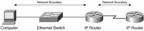 If multiple networks or subnets are configured on a single router interface, network/subnet independence is maintained by protocol behavior. This configuration represents a merit system and is discouraged. Independent operation of multiple networks or subnets on a single router interface can be enforced by creating sub-interfaces on the router interface. Each network or subnet is mapped onto a sub-interface, and each sub-interface is mapped onto a virtual network at the data-link layer (such as an Ethernet VLAN). The virtual network boundaries at the data-link layer then become the virtual network boundaries of the IP networks or subnets. Figure 6-8 illustrates the virtual boundaries of IP networks or subnets using Ethernet VLANs. The "router on a stick" configuration used during the early days of VLANs is shown because it visually depicts the network/subnet separation. However, this configuration is rarely used today. The best current practice (BCP) is a technique called "Layer 3 switching" that collapses the router functionality into the Ethernet switch. Figure 6-8. Virtual IP Network Boundaries IP packets sent to the local broadcast address of 255.255.255.255 do not cross IP network boundaries. However, routers can be manually configured to convert local broadcast packets to unicast packets and forward the unicast packets. This is typically accomplished on a per-protocol basis. The ULP identifier and destination IP address must be configured on each router interface (or sub-interface) expected to receive and forward local broadcast packets. This configuration promotes service scalability in large environments by enabling organizations to centralize services that must otherwise be accessed via local broadcast packets. For example, an organization may choose to forward all DHCP broadcasts from every subnet to a centralized DHCP server. In addition to the local broadcast address, IP packets can also be sent to a subnet broadcast address. This is called a directed broadcast because IP routers forward such packets to the destination subnet. No special configuration is required on any of the routers. Upon receiving a directed broadcast, the router connected to the destination subnet converts the packet to a local broadcast and then transmits the packet on the destination subnet. An example of a directed broadcast address is 172.45.9.255 for the subnet 172.45.9.0/24. Local broadcast packets can be forwarded to a directed broadcast address instead of a unicast address. This further promotes service scalability in large environments. For example, an organization that forwards all DHCP broadcasts from every subnet to a centralized DHCP server might overload the server. By using a directed broadcast, multiple DHCP servers can be connected to the destination subnet, and any available server can reply. DHCP and many other services are designed to support this configuration. Packet FormatsIP uses a header but does not use a trailer. The IP header format defined in RFC 791 is still in use today, but some fields have been redefined. IP packets are word-oriented, and an IP word is 4 bytes. Figure 6-9 illustrates the current IP packet format. Figure 6-9. Current IP Packet Format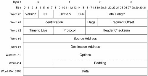 A brief description of each field follows:
The preceding field descriptions are simplified for the sake of clarity. For more information about the IPv4 packet format, readers are encouraged to consult IETF RFCs 791, 815, 1122, 1191, 1812, 2474, 2644, 3168, and 3260. Delivery MechanismsIP supports only one set of delivery mechanisms that provide unacknowledged, connectionless service. Transport layer protocols compliment IP to provide other delivery services. IP implements the following delivery mechanisms:
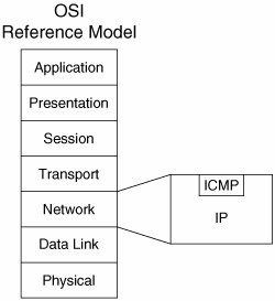
ICMPAs previously stated, ICMP compliments IP. ICMP is an integral part of IP, yet ICMP uses the services of IP for packet delivery. Figure 6-10 illustrates the architectural relationship of ICMP to IP. Figure 6-10. Architectural Relationship of ICMP to IP ICMP can be used for many purposes including error notification, congestion notification, route redirection, route verification, address discovery, and so on. Many ICMP message types are defined to accomplish these functions. A common packet format is defined for all ICMP message types. Figure 6-11 illustrates the ICMP packet format. Figure 6-11. ICMP Packet Format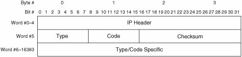 A brief description of each field follows:
Currently, 22 types of ICMP message are defined for IPv4. Of these, 15 are in widespread use today. Table 6-2 lists the currently defined ICMP message types for IPv4 and the codes associated with each message type.
Comprehensive exploration of all ICMP messages and their payloads is outside the scope of this book. For more information about ICMP, readers are encouraged to consult IETF RFCs 792, 950, 1122, 1256, 1812, and 3344. Interface and Port InitializationAfter a router (or other networking device) interface has been assigned an IP address and administratively enabled, it is ready to communicate with other IP devices. No special initialization procedures must be followed before communication. Likewise, no parameters must be exchanged between IP peers. This reflects the connectionless nature of IP. That said, certain routing protocols and ULPs implement initialization procedures, but the transmission of IP packets to facilitate those procedures does not require any initialization beyond address assignment. Aside from potentially different IP address assignment procedures, host ports can be viewed the same as router interfaces. That is, host ports can communicate with other IP devices immediately following IP address assignment. |

EAN: 2147483647
Pages: 196