OSI Reference Model
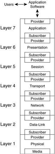
| The OSI reference model is defined in the 7498 series of documents published by the International Organization for Standardization (ISO). The primary document was originally published in 1984 and then revised and republished in 1994 as ISO/IEC 7498-1:1994. The ISO is responsible for thousands of standards, not all of which relate to information processing and communication. For this reason, the ISO is one of most important international standards bodies in the world. The OSI reference model is widely regarded as the preferred network model by which all networking technologies can be meaningfully compared and contrasted. Note Notice the acronym ISO does not align with the full name of the organization. The ISO wanted a common acronym to be used by all nations despite language differences. International Organization for Standardization translates differently from one language to the next, so the acronym also would vary from one language to the next. To avoid that problem, they decided that the acronym ISO be used universally despite the language. ISO derives from the Greek word isos, meaning equal. As a result of choosing this acronym, the organization's name is often documented as International Standardization Organization, which is not accurate. Network Models, Specifications, and ImplementationsA network model typically defines layers and functionality within each layer. A network specification typically defines how to perform the functions defined within each layer of a network model. A network implementation manifests one or more network specifications in hardware or software. The OSI reference model is not a network specification. The OSI reference model does not specify protocols, commands, signaling techniques, or other such technical details. Those details are considered implementation-specific and are left to the standards body that defines each specification. The OSI reference model provides common definitions of terms, identifies required network functions, establishes relationships between processes, and provides a framework for the development of open standards that specify how to implement the functions or a subset of the functions defined within the model. Note that the ISO provides separate protocol specifications based on the OSI reference model. Those protocol specifications are not part of the OSI reference model. Seven-Layer ModelThe OSI reference model comprises seven layers. Each layer may be further divided into sublayers to help implement the model. The common functionality that must be supported for a network to provide end-to-end communication between application processes is broken down into these seven layers. Within each layer, the services that should be implemented to achieve a given level of functionality are defined. Each layer provides services to the layer above and subscribes to the services of the layer below. Each layer accepts data from its upper-layer neighbor and encapsulates it in a header and optional trailer. The result is called a protocol data unit (PDU). The PDU is then passed to the lower-layer neighbor. A PDU received from an upper layer is called a service data unit (SDU) by the receiving layer. The SDU is treated as data and is encapsulated into a PDU. This cycle continues downward through the layers until the physical medium is reached. The logical interface between the layers is called a service access point (SAP). Multiple SAPs can be defined between each pair of layers. Each SAP is unique and is used by a single upper-layer protocol as its interface to the lower-layer process. This enables multiplexing and demultiplexing of upper-layer protocols into lower-layer processes. If a networking technology operates at a single layer, it depends upon all lower layers to provide its services to the layer above. In this way, the layers build upon each other to create a fully functional network model. An implementation of the model is often called a protocol stack because of this vertical layering. Figure 2-1 shows the seven OSI layers in relation to each other. Figure 2-1. Seven Layers of the OSI Reference Model The functions defined within each layer follow:
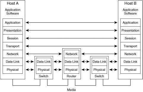
Layer 1Physical LayerThe physical layer (also known as the PHY layer) is responsible for media-related functions. Data units at this layer are commonly called frames. Details such as physical medium characteristics, physical connector characteristics, electrical and optical signal levels, rules for signal transitions, methods for maintaining direct current (DC) balance, acceptable signal-to-noise ratios, methods for filtering noise, receiver sensitivity, maximum physical link distances, medium error detection and notification procedures, signal timing and synchronization, data encoding techniques, and transmission rates are specified within this layer. Repeaters operate at this layer. Layer 2Data-Link LayerThe data-link layer is responsible for transport of data across a physical link. Variable-length data units at this layer are commonly called frames. Fixed-length data units at this layer are commonly called cells. This layer multiplexes network layer protocols into the physical layer process. Details such as medium-access algorithms, duplex settings (half or full), link-level node addressing (also known as physical node addressing), frame types, frame formats, frame sequences, maximum and minimum frame sizes, link-level flow-control mechanisms, handshakes and negotiation methods between Layer 2 entities for support of optional functions, frame and protocol error detection and recovery and notification procedures, protocol timeout values, physical topology, and network layer protocol multiplexing procedures are specified within this layer. A maximum link distance that is shorter than the underlying physical layer technology can support may be imposed by the data-link layer protocol. Multiple similar or dissimilar physical links may be interconnected by Layer 2 devices known as bridges to create an extended Layer 2 network. So, the methods for loop suppression, route discovery and selection, quality of service provisioning, protocol conversion, frame filtering, and frame forwarding are also specified within this layer as appropriate for each technology. Bridging functionality typically is not implemented in end nodes. Data-link layer protocols can operate in connectionless mode or connection-oriented mode. Data-link layer connections facilitate delivery guarantees within a network. So, the procedures for establishment, maintenance, and teardown of connections between pairs of bridges are specified within this layer. If virtual Layer 2 networks are implemented on a shared physical Layer 2 network, this layer is responsible for boundary determination and traffic isolation. Note In common terminology, bridge is somewhat antiquated. It typically refers to a relatively unintelligent device with two ports. The more mainstream term switch refers to a bridging device with very high port density, a crossbar for internal port interconnection, advanced intelligence, and other characteristics not found in the bridges of old. Layer 3Network LayerThe network layer is responsible for interconnection of physical and virtual Layer 2 networks, network path determination, and forwarding of data between interconnected Layer 2 networks. Data units at this layer are commonly called packets. This layer performs fragmentation of Layer 3 packets received on a network segment that supports a larger packet size than the outbound network segment. Fragments may be reassembled by this layer at a downstream Layer 3 device (rare) or at the destination host before the data is passed to the transport layer (common). This layer also multiplexes transport layer protocols into the data-link layer process. Details such as network-level node addressing (also known as logical node addressing), network addressing to identify each Layer 2 network, methods for summarization of network addresses, methods for network address discovery, algorithms for path determination, packet types, packet formats, packet sequences, maximum and minimum packet sizes, network-level flow-control mechanisms, network-level quality of service mechanisms, handshakes and negotiation methods between Layer 3 entities for support of optional functions, packet and protocol error detection and recovery and notification procedures, logical topology, and network protocol timeout values are specified within this layer. Routers operate at this layer. Network layer protocols can operate in connectionless mode or connection-oriented mode. Network layer connections determine the end-to-end path and facilitate delivery guarantees within an internetwork. So the procedures for establishment, maintenance, and teardown of connections between pairs of routers that implement connection-oriented network layer protocols are specified within this layer. Tip The phrase packet switching is often used to generically describe Layer 3 and Layer 2 devices. This sometimes causes confusion because Layer 2 data units are called frames or cells, not packets. Layer 4Transport LayerThe transport layer is responsible for end-to-end communication between network nodes. Data units at this layer are commonly called packets. This layer performs segmentation of data received from the session layer into smaller chunks called segments. Segments may or may not be reassembled by this layer at the destination host before the data is passed to the session layer. Likewise, segments that are received out of order may or may not be reordered by this layer at the destination host before the data is passed to the session layer. This layer also multiplexes session layer data streams into the network layer process. Transport layer protocols can operate in connectionless mode or connection-oriented mode. Transport layer connections facilitate end-to-end delivery guarantees. So the procedures for establishment, maintenance, and teardown of connections between pairs of end nodes are specified within this layer. Details such as packet types, packet formats, packet sequences, packet- and protocol-error detection and recovery procedures, node-level flow control mechanisms, node-level queuing mechanisms, connection establishment and maintenance and teardown procedures, maximum segment sizes, segment sequencing and re-ordering procedures, transport protocol timeout values, methods for packet loss detection, and procedures for packet retransmission are specified within this layer. Layer 5Session LayerThe session layer is responsible for end-to-end communication between applications. Data units at this layer are commonly called protocol data units (PDU). Session-layer protocols can operate in connectionless mode or connection-oriented mode. Session-layer connections facilitate the orderly exchange of data between applications. Various details are specified within this layer such as the identification of well-known server applications, procedures for dynamic identification of client applications, procedures for session establishment and teardown, mechanisms for resynchronization of a session to a known state, mechanisms for arbitration between presentation-layer protocols to support prioritized access to session layer services, and procedures for suspension and resumption of presentation layer dialogues. Layer 6Presentation LayerThe presentation layer is responsible for data representation. Details such as character sets, graphic encoding algorithms, encryption algorithms, and compression algorithms are specified within this layer. This layer identifies the supported data syntaxes and negotiates which to use during each session. Layer 7Application LayerThe application layer is responsible for providing the services of the network to application software. An instance of an application running in one host relies on the application layer to identify other hosts running an instance of the application and to verify the target instance is available. This layer also determines an application's quality of service requirements, negotiates security parameters for authentication and authorization and data integrity, negotiates error recovery parameters, negotiates the mode of dialogue between applications, identifies the abstract data syntax to be used, and synchronizes the activities of cooperating applications. Implementation ConsiderationsIt is possible for end-to-end communication to occur between two nodes that implement only a subset of these layers. The network functionality provided would be less than that achievable by implementing all layers, but might be sufficient for certain applications. Each layer implemented in one network node must also be implemented in a peer node for communication to function properly between that pair of nodes. This is because each layer communicates with its peer layer implemented in another network node. The OSI layer peer relationships are illustrated in Figure 2-2. Figure 2-2. Network Node Communication Strict adherence to the OSI reference model is not required of any networking technology. The model is provided only as a reference. Many networking technologies implement only a subset of these layers and provide limited network functionality, thus relying on the complement of other networking technologies to provide full functionality. This compartmentalization of functionality enables a modular approach to the development of networking technologies and facilitates interoperability between disparate technologies. An example of the benefits of this approach is the ability for a connection-oriented physical layer technology to be used by a connectionless data-link layer technology. Some storage networking technologies implement only a subset of functions within one or more of the layers. Those implementation details are discussed in the following sections. |
EAN: 2147483647
Pages: 196