Summary
|
| < Day Day Up > |
|
Determining Your Need for Additional Resources
Now that we have determined some of the advantages and disadvantages of dividing our backup domains, we will look at when we need to add more device hosts or media servers, tape capacity, or perhaps even both.
| Note | VERITAS uses the terms device host and media server interchangeably to indicate a server that has some control of physical devices for the purposes of backup and restore with regard to VERITAS NetBackup. |
When to Add More Device Hosts
Again using the NetBackup illustration, the good news is that adding device hosts or media servers is not as daunting a task as determining whether or not to divide your backup domain. Typically when you find that you aren't meeting your backup window, but you have plenty of capacity in your tape library, it's a sure sign that you need to add a media server. By performing some very basic mathematical formulas, you can determine the approximate amount of data your current environment can actually handle. First, identify any bottlenecks in your backup environment before you decide that you need to invest in more of anything.
As an example, let's look at a master server with one network interface and a 100-Mbps Ethernet on a switched backup network, illustrated in Figure 9.7.
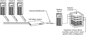
Figure 9.7: 100-Mbps network bottleneck.
A single 100-Mbps interface is capable of handling approximately 12.5 MB/second, or roughly two DLT8000 drives at native speeds of 6 MB/ second. This definitely looks like a potential bottleneck, and one would more than likely benefit by having an additional media server in place to share the burden.
With a GbE between the backup server and the switch, as illustrated in Figure 9.8, you can drive 125 MB/sec into the backup server, or approximately 20 DLT 8000 tape drives. Naturally, all of this would be dependent on the I/O interface to the tape drives, but assuming you had multiple SCSI interfaces or were using Fiber-connected drives, the numbers would hold fairly true. Would you really want to drive 20 DLT drives from one backup server? Probably not. At that point you would want to expand to another media server or another tape drive type. Table 9.2 shows tape drive statistics that you can use to help decide which drive type might be best.
Either by inheritance, slow growth, or, quite frankly, a very tight budget year, we will one day be faced with a backup environment that hops across networks. When the time comes, and budgets are loosening up, you definitely want to consider introducing a media server into this type of environment. Not only are you backing up another network, but also you are pulling all of that data across the network back to the media server to be written to tape. Wouldn't it be better to have that data remain within the network of its origin and only have to send the meta data back to the master server? We hope you answered yes. If you didn't, you are probably still under very tight budgetary constraints.
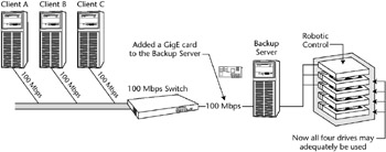
Figure 9.8: GbE network enhancement.
| NAME | NATIVE SPEED | CAPACITY | COMPRESSION | CAPACITY MAX |
|---|---|---|---|---|
| DLT8000 | 6 MB/sec | 40 GB | 2:1 | 80 GB |
| SDLT220 | 11MB/sec | 110 GB | 2:1 | 220 GB |
| SDLT320 | 16MB/sec | 160 GB | 2:1 | 320 GB |
| IBM LTO Ultrium | 15 MB/sec | 10 GB | 2:1 | 200 GB |
| STK T9840B | 19 MB/sec | 20 GB | 2:1 | 40 GB |
| STK T9940A | 10 MB/sec | 60 GB | 2:1 | 120 GB |
Let's look at an illustration to clarify this. In Figure 9.9, there is 1 TB of data located on clients D, E, and F. If that is true, there would be a significant impact on performance when backing up between networks. Adding a media server would streamline this solution by increasing the aggregate throughput through this division of labor.
As you can see from Figure 9.10, we took into consideration that we had more than enough tape drives for our data requirements, but not enough horsepower. So instead of purchasing more tape drives and another tape library, we were able to connect two of the drives to the new media server and keep two of the drives on the master server. This may not be possible in the event that distance plays a role, in which case it would be prudent to then size the appropriate tape library for the second location and deploy another media server along with it.
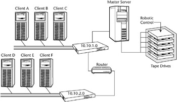
Figure 9.9: Multiple network bottleneck.
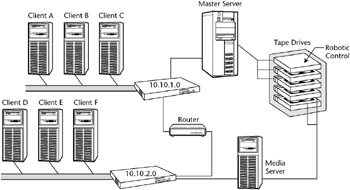
Figure 9.10: Network enhancement.
Another reason to add a media server may be that the amount of data on a particular server has so grossly outgrown even the ability of the network to handle the transfer that it makes good business sense to upgrade that machine to become a media server. For example, let's say that under the best circumstances, it takes a GbE network 23 hours to do a full backup of a server with 1 TB of data that needs to be backed up regularly. That is to say, 43 GB/hour is what our network can handle based on the numbers we charted earlier. We need to carry 1 TB, or 1000 GB, of data to the media server with a full backup, so dividing 1000 GB by 43 GB/hour gives us 22.72 hours. This probably doesn't meet the acceptance criteria for data protection at your facility, so the options are to either break down that server's storage or perform local backups by making this server a media server. Using what you learned in the Laying Out Your Backup Domain section in Chapter 3 to determine the memory, I/O, and processor requirements, make sure this new media server will be adequately outfitted with enough power to produce the results you expect.
More Tapes or Tape Drives, or Both?
Again, we cannot stress enough that, in order to get the most out of your current and future investments, you need to find the bottlenecks in your environment before you start spending money. After you have done your due diligence, adding more tape is reasonably simple, especially if you went through the capacity planning section at the beginning of this chapter. If you find that you are getting errors in your backup reports saying backups are incomplete because of unavailable media, you have an issue you need to address. This is done by understanding what is happening to your media. For example, has it had multiple media errors during a previous backup session? If this is the case, has your backup application, in this case NetBackup, marked this media unusable by freezing it? In this situation, you should create media reports and view the status of all the media, identify those that have been marked unusable or frozen, and then investigate why this is happening. Alternatively, if your media appears to be just fine except for the fact that most of it is in a full condition, you may have to remove some of the full media and replace with scratch media. If that is not an option, consider a larger tape library or an additional tape library.
When should physical tape drives be added? Well, again, it all comes down to math. If you have gathered all of the information related to your clients-tape drives, network speeds, SCSI speeds, fiber speeds-and so on, you are well armed to report whether your current environment will tolerate the amount of data you are looking to protect. See Table 9.3. You want to avoid 'shoe-shining' the drives as much as possible. Shoe-shining is a term used to describe a situation where a drive is not receiving data fast enough to keep writing and must wait to receive data; therefore, it rewinds a bit to reposition, then begins writing when the data finally arrives.
Now we will lay out some basic planning formulas that may be used in your quest for backup utopia. (By the way, if you ever find backup utopia, please let us know.) First, gather the information needed to perform the math:
-
Network speed (10 Mbps, 100 Mbps, 1000 Gbps, etc.)
-
I/O speeds to the storage device (SCSI, Fibre, Disk Channel, etc.)
-
Output device speeds (we use the native speeds)
| TYPE OF SERVER | NETWORK FEEDS | I/O SPEEDS | NATIVE DRIVE SPEEDS | OBSERVATIONS |
|---|---|---|---|---|
| Master server | 100 MB/sec | 40 MB/sec × 2 (2-SCSI) | 11MB/sec × 6 (6 SDLT 220s) | Find lowest common denominator |
| Real numbers | 12.5 MB/sec | 80 MB/sec | 66 MB/sec | Network is a bottleneck |
| Proposed | Upgrade to GbE | 3 -drives / SCSI | Maximum Reached | To achieve maximum throughput |
| 1000Mbps | 40 MB/sec × 2 | 11 MB/sec × 3 on SCSI A | 33 MB/sec | |
| 11 MB/sec × 3 on SCSI B | 33 MB/sec | |||
| 125 MB/sec | 80 MB/sec | Total aggregate 66 MB/sec | ||
| Best practice to avoid shoe-shining | 1GbE | 40 MB/sec × 3 | 11 MB/sec × 2 on SCSI (22 MB/sec) | Headroom for burst speeds on the drives, which may |
| (125 MB/sec) | (120 MB/sec) | 11 MB/sec × 2 on SCSI B (22 MB/sec) | reach 22 MB/sec | |
| 11 MB/sec × 2 on SCSI B (22 MB/sec) |
Now, assuming of course that you used the recommendations in Chapter 4 for your server component selection, such as memory, processors, and so on, you will be on your way to that utopian land we all strive for. All of the 'busy' work may seem a bit mundane, but it is a very worthwhile exercise, especially during budget time. See Table 9.4.
It's very helpful to create charts and spreadsheets like this for each of the servers you plan on using. Not only does it help you with these architectural decisions, but it may be the basis for your own site documentation, a task we all love to do. Furthermore, this exercise applies whether or not you are using NetBackup.
| TYPE OF SERVER | NETWORK FEEDS | I/O SPEEDS | NATIVE DRIVE SPEEDS | OBSERVATIONS |
|---|---|---|---|---|
| Master server | 1GbE | Fibre Channel (100 MB/sec) | 15 MB/sec × 4 (4 LTO Ultrium) | Find lowest common denominator |
| Real numbers | 125 MB/sec | 100 MB/sec | 60 MB/sec | Room for ~2 - 3 more LTO drives |
| Best practice | 125 MB/sec | Fibre Channel | Add two more LTO drives, bringing aggregate total to ~90 MB/sec | To achieve maximum throughput |
What about Tape Technologies?
Many tape technologies are on the market; some were listed earlier in this chapter. How do we answer that question for you in these pages? We really cannot. You will know if you need new tape technology based on your due diligence. Nothing we can write here will tell you definitively that you should change your tape technology (unless, of course, you are using a QIC drive for your backup; in this case, we would feel safe recommending that you at least give it some thought). But even after you have done your due diligence, what if you have a system that cannot push the data any faster than the QIC drive can read? What if we said you should move off of those DLT 8000 drives and get into something faster without first looking at your server, NIC, or I/O to the drives? This would, of course, be ridiculous, and anyone that claims they can tell you different may also have a bridge in backup utopia to sell you too. Do some investigating. Interview the vendors, asking them for real benchmark test results, for the native speeds of their drives, not the theoretical numbers. Always look for the disclaimer, 'your mileage may vary'-another way of saying results are not typical. Take the time to perform the math calculations and see exactly what you are getting yourself into before you put your name on a proposal that carries a price tag of $1.2 million. Otherwise, you might find yourself surprised.
Alternative Network Solutions
How to continue to meet the expectations of the business and finish your backups within the allotted time continues to stand before us. There are some very good alternatives to the traditional approach; most of what will be covered in this section has become more of the norm rather than the exception. In this section we briefly cover the other network solutions you might want to look into as your backup system needs to expand and keep up with the expectations of the business.
-
10 Mbps, 100 Mbps, 1 GbE
-
Dedicated backup network
-
Storage area network (SAN)
10 Mbps, 100 Mbps, 1 GbE
As we were evaluating our network looking for bottlenecks, we touched on the subject of moving up from 10 Mbps to 100 Mbps, or even 1GbE (1000 Mbps). The benefit as you slide up the scale is more and more data being moved along the network pipe, and today most people have a switch in their environment for their large servers. If you don't, that might be the first thing you place on the budget proposal for the next fiscal year.
There are several camps on this subject, but the rule of thumb we have always used has been the effective throughput of an Ethernet network is 1.25 MB/second for 10 Mbps, 12.5 MB/second for 100 Mbps, and 125 MB/sec for 1000 Mbps (1GbE), and even then, we tend to round those numbers down. See Table 9.5.
We know some people, ourselves included, who use these numbers and apply an overhead reduction to them of approximately 30 percent. It is a good baseline to start with while you are looking into the possibilities of uplifting your network to a higher-speed technology. With the knowledge of the previous sections in this chapter, you should be much better equipped to size or plan the deployment of your backup solution.
| 10 BT | 10 Mbps | 1.25 MB/second |
| 100 BT | 100 Mbps | 12.5 MB/second |
| Gig Ethernet (1000 Mbps) | 1000 Mbps | 125 MB/second |
Dedicated Backup Network
You may find that even by upgrading your network bandwidth to 100 Mbps or even 1 GbE your primary network is so busy during the evening hours when backup runs that it would still hinder performance. That's when you want to consider implementing a dedicated backup network. These are great if you can afford to put one in. All of the backup data travels across this dedicated backup network and nothing travels across your public network. Many customer sites that we have visited have dedicated backup networks, and the performance benefits are tremendous. A dedicated backup network requires an additional interface in the servers to be hosted on this new network. This also may require some configuration modifications to your backup software in order to ensure you are using the dedicated network versus the public network. One of our customers has two dedicated networks, as shown in Figure 9.11.
Normally, this would be a good time to recommend that you deploy another device host, or media server. However, while on site, we discovered that they had plenty of horsepower in the master server to drive the tapes and receive the data, so it wasn't necessary to install another server in the domain. Instead we opted for another NIC to allow this server to method and saved the client's budget for other things in the enterprise.
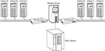
Figure 9.11: Dual networked master.
Another method similar in look and feel is a SAN.
Storage Area Network (SAN)
Sometimes called a TAN, for tape area network (if that's all being hosted on the switches), a SAN usually consists of some kind of fiber or fabric switch, host bus adapters (HBAs) in the servers, and a zoning configuration on the switches to ensure proper routing of devices and information. A SAN is very similar to what you are used to with traditional networking. A LAN, for instance, consists of a switch or even a hub that has servers and other computing devices attached to it for the purposes of sharing resources. Similarly the main purpose of a SAN is to share resources, but instead of a 100-Mbps switch, it is a fiber switch. Not only can servers attach to it but also storage devices, such as disk and tape. A SAN is not as complex as you might think. Really, if you think about it, networking is just plumbing. You have a variety of pipes that connect together in order to deliver something. In a home, it's water; in a data center, it's data. So we have this elaborate piece of plumbing that allows the sharing of resources in a very efficient and surprisingly fast manner.
Figure 9.12 is a basic design of a SAN, two SAN routers for redundancy, a SCSI-to-Fibre bridge in order to bring the tape drives into the SAN, dual HBAs in the servers, and a master server, all connected to the SAN switches. This type of configuration would enable the data to be read from the SAN-attached clients and written to the SAN attached tapes, without having to traverse the public network with large amounts of data.
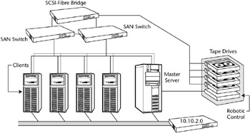
Figure 9.12: SAN attached master server.
There are many more possibilities with SANs in a NetBackup environment, which we discussed in the Backing Up and Restoring in a SAN Environment section of Chapter 7.
|
| < Day Day Up > |
|
EAN: 2147483647
Pages: 176
- Information Security and Risk Management
- Security Architecture and Design
- Business Continuity Planning and Disaster Recovery Planning
- Appendix C The Information System Security Architecture Professional (ISSAP) Certification
- Appendix E The Information System Security Management Professional (ISSMP) Certification