| You'll continue creating the head you began in Chapter 6, "Polygon Character and Subdivision Surfaces Modeling." The critical parts of setting up the face were done in Chapter 6, as you positioned the crucial vertices for the eye, nose, and mouth. Now, the work is more straightforward connecting all the parts and fine-tuning the mesh for optimal layout, while making minor positional changes to the vertices to improve the likeness. However, one of the more complex shapes of the head the ear is modeled in this chapter. Luckily, it doesn't need to be as perfect as the facial features to get a likeness of the person you're modeling. Some of the Maya concepts covered in this chapter include the following: Subdivision Surfaces Maya offers a special kind of geometry called Subdivision Surfaces, which are excellent for modeling and shaping smooth shapes. Smooth Proxy A simpler way to model smooth organic shapes, Smooth Proxy mode has the advantage of being fast and responsive as you edit. In this chapter, you'll use it to help visualize the smoothed face as you work. Instancing An object can be copied in a way that makes it reflect the source object, despite any move, rotate, or scale transform you apply. This is called an instance copy, and it is ideal when you want automatic symmetry, as in this human-head model. Reference layers Sometimes, you want to see a layer but not have it interfere with your work. Setting a layer to Reference mode prevents objects on that layer from being selected as you work.
Key Terms Smooth Proxy An automatic mode Maya can configure that enables you to control a smoothed polygonal object with a lower-resolution unsmoothed polygonal object. nonmanifold Sometimes, geometry can exist in a form that renders correctly but doesn't work well with processes that expect contiguous single-surfaced uniform objects. Improper geometry is sometimes called nonmanifold. quads These four-sided polygons are the preferred shape for polygons that make up a SubD surface because they smooth predictably. SubDs An abbreviation for Subdivision Surfaces. full crease Subdivision Surfaces allow sharp folds using creasing applied to edges. partial crease A less sharp form of a full crease. |
Hotkeys to Memorize Ctrl+Shift+D Open Duplicate Options dialog box. 1, 2, 3 Smoothness settings for Subdivision Surfaces. |
Tutorial: Combining the Parts of the Face First Tweaks In this tutorial, you'll make the final adjustments to the head sections so that you can attach all the parts of the head together. After attaching the parts, you must weld the vertices together so that all the polygons are interconnected. That is, the corner vertices of each polygon are shared with its nearest neighbors; simply combining polygons doesn't make the vertices weld. Finally, you'll make some additional tweaks to improve the head topography. Begin with your ending file from Chapter 6 or load the file noted next to the DVD icon. On the DVD  Chapter_07\movies\ch07tut01.wmv |
On the DVD  Chapter_06\ch06tut06end.mb |
First, enable Wireframe on Shaded mode in your Perspective viewport (choose Shading | Shade Options | Wireframe on Shaded from the panel menu). This mode helps you see the edges you're adjusting as you orbit the Perspective view. Look for places where there's an inconsistency in edge count between parts of the face. When you find them, you can split pieces to add edges or merge vertices to get rid of edges. For this step, split the sections (Hotbox | Edit Polygons | Split Polygon Tool). Create three new divisions in two sections, as shown in Figure 7.1. For each section, click on the edge in the Perspective view, then orbit, zoom, or pan the Perspective view for a better view for the next split, and then click again. After placing the last point, press Enter to perform the split. Figure 7.1. Adding splits to make each section have equal numbers of neighboring edges. 
tip If you want to step backward one step while doing splits, use the Backspace key. Now, select one of the newly subdivided sections of the face. Right-click over it and choose Vertex. Select one of the newly created boundary vertices, and switch to Move mode (hotkey: w). Now, vertex-snap by holding down the v key while moving (also known as point snapping). Snap the vertex to the neighboring vertex. Repeat for the two other boundary vertices, as indicated in Figure 7.1. tip Because the vertices in these boundary areas are next to each other but separate, make sure that you select the two vertices together with a marquee selection so that you can move them together. Now, adjust the position of these three vertices for the new edges to help give them a better shape round them out a little by pulling them forward. Exit Component mode with F8. Draw a marquee-selection window around all the polygon meshes. Combine the separate objects into a single object (Hotbox | Polygons | Combine). Now, the head is one object. Right-click over the head object and choose Vertex. Select all the vertices with a marquee-selection window around the entire head. Click Hotbox | Edit Polygons | Merge Vertices | option box. In the Merge Vertices Options dialog box, set the Distance value to 0.0001 so that only vertices on top of one another are merged together. Because all the vertices were point-snapped to one another earlier, merging all vertices with a very low Distance setting should handle the procedure in a single operation. Confirm that the vertices were welded correctly by going to Component mode, clicking over individual vertices, and testing what happens when they're moved. Try this on vertices at the boundary of where the face sections were before you combined them. If the vertices welded properly, a single vertex should control all the faces it borders. Now, you'll refine the nose to make it look more realistic. Right-click over the head and choose Face. Select the two faces of the nostril, as shown in Figure 7.2. Extrude them with Edit Polygons | Face Extrude. Be sure you've select Polygons | Tool Options | Keep Faces Together first so that you don't create an extrusion for each face. Figure 7.2. Extruding and shaping the side of the nose. 
Move the vertices around to form the outside of the nostril. After you smooth them, this will help make the shape nice and rounded. Use Hotbox | Edit Polygon | Split Polygon to create a split from the leftmost edge you just created running vertically down through the nostril to help round out the front of the nostril and extend the line around the nose. You'll probably find this easiest in the Perspective view, with careful rotational adjustments to follow the split you're creating all the way up the nostril. Use the four views shown in Figure 7.3 as a guide. Figure 7.3. Adding splits to the nostril to create a more rounded shape. 
Adjust the new vertices created by the splits in step 10 to round out the front of the nose. Exit Component mode with F8. Now, you'll do a quick test of what the head will look like when it's smoothed by converting the mesh to a SubD object. With the head selected, choose Hotbox | Modify | Convert | Polygons to Subdiv. Most likely, the conversion won't work because as you created the parts of the face, Maya assigned a "direction" in which the faces point, called the surface normal. If some parts of the face point "in" (toward the center of the head) and some point "out," the geometry won't convert. Luckily, you can easily fix this with a global command: Choose Hotbox | Polygons | Cleanup | option box. Make sure the Nonmanifold Geometry check box is selected and the Normals and Geometry radio button is selected. Click Apply while the head model is selected, and the geometry should be corrected. Problem areas that were fixed are indicated by shading in the viewport (see Figure 7.4). Figure 7.4. Fixing nonmanifold geometry with the Cleanup command. 
Exit Component mode with F8. Try again to convert to Subdivision Surfaces, as shown in step 12. You might notice unnatural creases and grooves, particularly around the eyebrow, nostril, and lower lip. Take a moment to remember the areas in question, and then undo (hotkey: Ctrl+z) the conversion. trap If holes appear in the face when you successfully convert to SubDs, you have vertices that didn't weld in step 6. Go back and vertex-snap any vertices in the areas where the holes appeared to make certain they're directly on top of the nearby facial vertices. Merge the vertex shown in Figure 7.5 by point-snapping the vertex on the upper part of the nose to the one at the eye to get rid of the bump that was showing up. Then, marquee-select both vertices that are next to each other and merge them, as shown in step 6. Figure 7.5. Merging a vertex on the bridge of the nose to reduce the number of faces. 
Adjust the position of other vertices in the area so that the forehead is smooth and flowing and there aren't any bumps. Try to keep edges that connect in a line from zig-zagging.
Tutorial: Smooth Proxy Visualization and Fine-Tuning Splits In this tutorial, you'll use the Smooth Proxy option in Maya to get a fast-response smoothed version of the head. Also, to finally get a look at what you really have, you'll create the other half of the face by mirroring the model as an instance. Then, you'll fine-tune the head shape further. On the DVD Chapter_07\movies\ch07tut02.wmv |
On the DVD Chapter_07\ch07tut01end.mb |
First, you'll make a smooth proxy of the head. Select the head and choose Hotbox | Polygons | Smooth Proxy. You'll notice that two layers are added to the Layers dialog box (if this dialog box isn't displayed, choose Hotbox | Display | UI Elements | Channel Box/Layer Editor). Notice that the coarser "cage" object is semitransparent and the smoothed version is opaque. Maya automatically makes the smoothed result layer a Reference layer. This means it can't be selected, so you can work with the object without accidentally selecting it. Click on the R in the Layers dialog box to clear that check box so that you can edit this layer. Now, select the smoothed mesh instead of the low-resolution cage. (You might need to select the subdivided geometry from inside the head in the Perspective view or select it by right-clicking on its display layer and choosing Select Objects.) tip In the Smooth Proxy Options dialog box, you can increase the number of divisions to make the resulting surface smoother. You can also set this number in the Channel Box. For the time being, leave it set to 1 for faster performance. Duplicate the smoothed half-head (Hotbox | Edit | Duplicate | option box; hotkey: Ctrl+Shift+D). Reset the settings (Edit | Reset Settings). It's always a good idea to reset the settings in any dialog box that hasn't been used recently. Set Geometry Type to Instance and set Scale X to 1. This makes the new copy a mirror, so it copies any changes made to the original. note The two face halves remain separate objects. The centerline between these two sides isn't welded, so you might see a seam along the split. However, the two sides should touch. At this point, you can turn off Wireframe on Shaded mode in your Perspective viewport (choose Shading | Shade Options | Wireframe on Shaded from the panel menu). This keeps the overlay smooth and prevents cage objects from getting confusing. With the new duplicate still selected, right-click over the Layers dialog box on the smooth proxy layer, and choose Add Selected Objects (see Figure 7.6). This puts the new geometry in the same layer as the original half. You can test this by toggling the V (visibility) check box on the layer and confirming that both smoothed halves disappear. Figure 7.6. Adding the instanced and mirrored smooth copy to the smoothproxy layer. 
In the Channel Box, display the smoothing settings by clicking on the polySmoothFace name and changing the Divisions setting to 2 for increased smoothness. Turn the layer with the smoothed geometry back into a Reference layer by clicking on the empty check box in the Layers dialog box until the R is displayed again. Now, the object can't be selected. Now, you can adjust the low-resolution cage mesh and see the results on both sides of the head instantly. You're ready to continue editing the mesh. As a first measure to fix the diagonal crease above the bridge of the nose, use the Split Polygon tool to cut from the outer point of the two triangle faces at the ridge of the nose and make three splits going up the head (see the leftmost image in Figure 7.7 for reference). Make sure to click and drag along the first horizontal edge to the corner point as you start the first split this ensures that you're splitting the polygon at the corner, not at a midpoint of the face. Figure 7.7. Split, delete, delete, and split. The visibility for the smooth layer has been toggled off in this figure. 
Right-click over the mesh and choose Edge. Select and delete the indicated edge (see the second from the left image in Figure 7.7) of the triangular face to turn it into a four-sided polygon a quad. Quads are always best in higher detailed portions of the face because they're less likely to create problems with smoothness. Delete the edge to the left of the one you just deleted to get rid of that triangle, as shown in the third image from left in Figure 7.7. Create two polygon splits to create the edges shown in the rightmost image in Figure 7.7. As in step 8, make sure to drag along the edge to the vertex point for the start and end split points. This moves the triangular split up to the forehead area, which is flatter and easier to shape. Select and move the vertices above the bridge of the nose to make the smooth surface transition more even in this area. This fixes the crease that was evident in the forehead. Begin reshaping the nose, paying attention to how it looks smoothed, so that there are no ugly creases. Also, smooth the outer area of the eye to remove any dents or creases around it. If so, smooth them by moving the appropriate vertex. See Figure 7.8 for guidance. You can judge smoothness by observing the mirrored half in the shaded Perspective view. Figure 7.8. Some facial areas that aren't baby-smooth need a little adjustment. 
Switch to Edge mode, and select the inner edges forming the inside of the lips. Extrude these edges backward (click on the blue circle handle to do an extrusion that goes straight backward), as shown in Figure 7.9. Move the vertices around to form the rest of the lips, leaving a small hole in the center as though the mouth is barely open. Figure 7.9. Extrude the inner edge of the lips to add more thickness and depth. 
Move the vertices to form the shape of the inside of the lips and correct any overlapping polygons. Adjust the vertices going around the head in the Side view to give the head a smooth rounded shape, as shown in Figure 7.10. Where the model's hair covers the shape of the back of the head, use a good guess. The model refused to shave her head for the benefit of this book's readers go figure! Figure 7.10. Side view of the head after making adjustments for smoothness and shape. 
tip A "ring" of edges is also known as an edgeloop. To select an edgeloop quickly, first select an edge, and then choose Edit Polygons | Selection | Select Contiguous Edges. This command selects all the edges that follow in the same path.
Tutorial: Eyes Refining the Face In this tutorial, you'll add some eyes to make the face look more human, and then add splits and refinements to improve the shape. On the DVD Chapter_07\movies\ch07tut03.wmv |
Create a NURBS sphere (Hotbox | Create | NURBS Primitive | Sphere). In the Channel Box, set Scale X, Y, and Z to 1.436 and Translate X, Y, and Z to 2.481, 1.904, and 6.152. You might need to use slightly different values if your head's shape varies a little from the tutorial at this point. This sphere will stand in as an eye to help you judge the look of the face. Now, duplicate it (hotkey: Ctrl+Shift+D) and reset the settings. Change the Translate X value to the negative of the amount used for the first sphere to move this eye to the mirrored point. (For example, if you used the same values for the first sphere, now you'd use 2.481 for Translate X.) On the DVD Chapter_07\ch07tut02end.mb |
The nose and mouth still have some unwanted dimples and topography problems that you'll correct in the next steps. Referring to Figure 7.11, delete the edge for the triangle at the tip of the nose. Figure 7.11. Refining the nose and mouth area. 
Use the Split Polygon tool to add the two splits indicated in Figure 7.11 (second image from left). This edit changes the two polygons to four-sided quads. Another horizontal split in the nose will give you more control for shaping the nose and rounding its outside shape. Using the third image from the left in Figure 7.11, split the polygons with the Split Polygon tool through the center of the lower nose and continue down to the corner of the mouth. A total of 9 divisions are created with 10 clicks. Coming down the side of the mouth, divide along the crease, as shown in the Front view photo, so that a crease can be formed to add dimples later. All splits are more or less at the center of the edge, except for the fourth-from-last and last points, which should be dragged along the edge to connect at the corner points. Referring to the rightmost image in Figure 7.11, create a vertical split in the nose. This split starts at the centerline of the lower nose and works around to the inside of the nostril. Create the splits in the Perspective view, orbiting, zooming, and panning between each split to get the ideal position for placing the next split. In the Side view, tweak the vertices' position to help smooth the nose. Pay attention to the smooth mesh for dents and creases. Use the Split Polygon tool to make the three cuts indicated in the left image in Figure 7.12. This adds a softening line for the mouth crease. Figure 7.12. The left image indicates the splits to be added; the right image indicates an edge to delete. 
Delete the edge indicated in the right image in Figure 7.12. This returns some of the triangles to quads. Take a few minutes to tweak the head's vertices to smooth out any other obvious bumps or zig-zags in the lines of the face. More global edits can be postponed for now. Now, delete all the layers (right-click over the layer name in the Layers dialog box and choose Delete), and delete the face's two smooth proxy halves (select and delete) to prepare to add the ear. Also, make the polygon cage solid again by right-clicking over it and choosing Materials | Assign Existing Materials | Lambert.
Tutorial: Building the Ear The human ear is a complex and curvy shape that's easily modeled. To help you understand the topology you'll use, see Figure 7.13. Figure 7.13. An overview of the boundaries to be used in modeling the ear. 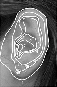
On the DVD Chapter_07\movies\ch07tut04.wmv |
Figure 7.13 shows seven curves that follow the shape of the ear. Start with the outermost line: Line 1: Outer edge of the ear On the DVD Chapter_07\ch07tut03end.mb |
Line 2: Inside limit of the outer rim of the ear Line 3: Edge of the first rim Line 4: Edge of the lower ear rim Line 5: Edge of the second rim Line 6: Ear funnel top (hole edge rim) Line 7: Ear funnel (hole edge) Each boundary is built from edge extrusions, as in the face construction methods used in Chapter 6. To create the ear, choose Hotbox | Polygon | Create Polygon Tool to draw the outline of the ear in the Side view. Use 13 points around the ear to match the figures in this tutorial. Press Enter to finish creating the polygon. Switch to Move mode and position the new ear polygon on the side of the head to make it easy to locate. Translate X should be approximately 7 in the Channel Box (see Figure 7.14). Figure 7.14. Position the ear polygon. 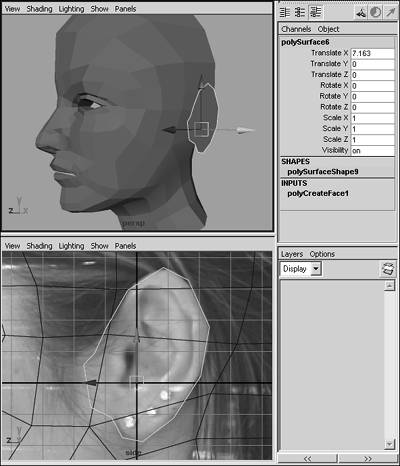
Select the ear polygon, and then extrude it and scale it smaller so that the shape moves inward (Hotbox | Edit Polygons | Extrude Face), as shown in the leftmost image in Figure 7.15. Figure 7.15. Building the first rings of the human ear. 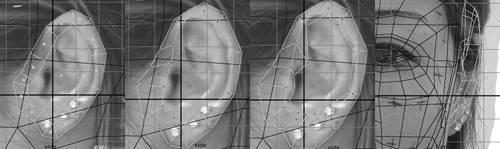
Move the vertices so they line up about halfway with the outer ring of the ear. Use the second image from the left in Figure 7.15 as a guide. Select and extrude this new row of edges inward. Move the vertices to align them to the inside part of the outer ring, as shown in the third image in Figure 7.15. In the Side view, edit the image plane settings for the currently dominant headSIDE.jpg image (View | Image Plane | Image Plane Attributes), and select the image plane showing the female face with projected grid lines. In the Attribute Editor, under Placement Extras, change the Center X value from 19 to 21. This moves the image plane to the back to expose the original image plane, which you can confirm in the Side view. Repeat for the Front view, but set Center Z to 21 because the Front view is looking down the Z-axis (the Side view looks down the X-axis). The original image planes might not match very well now, and they're somewhat cut off in the Side view. However, the key point here is how far the ear extends out from the head in the Front view. In other words, what is her Prince Charles factor? Before things get more complicated, you'll give the ear some thickness. Switch to the Front view and move the points along the X-axis to match the rightmost image in Figure 7.15. Select the inner polygon face, extrude it, and scale it inward again. Move the vertices so that they lie inward near the outer ring, creating the ring shape. Then, adjust the vertices further to create the tab in the ear that protrudes up from the earlobe, as shown in the leftmost image in Figure 7.16. Figure 7.16. Progression of building the human ear. 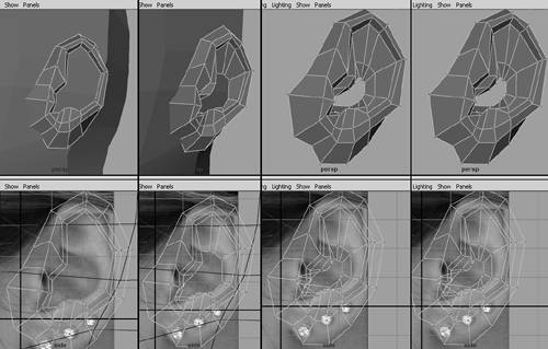
note In case you've ever wondered, that little tab in your ear is called the antitragus. Select the center face again. Extrude it inward and scale it smaller. Move to the new vertices to create the first major dips down by the earlobe. The upper vertices you created fall much farther below the top edge to form the sloping shallow area of the upper ear (see the second image from the left in Figure 7.16). Select the center face again. Extrude it and scale it inward, and then move it toward the ear hole, as shown in the third image from the left in Figure 7.16. Create a layer in the Layers dialog box and assign the head to it. To do this, select the head, right-click over the new layer, and choose Add Selected Objects. Now, you can easily toggle the head on and off by clicking the V check box for this layer when you need to work on the inside of the ear. This makes it easier to prepare a correctly built hole in the side of the head for the ear attachment point. You'll also merge three pairs of vertices in the center of the ear shape. These points are close together, so it will simplify your work to have fewer points as the ear shape converges at the center. Right-click over the mesh and choose Vertex. Carefully select the two vertices you'll merge (refer to Figure 7.16). Choose Hotbox | Edit Polygons | Merge Vertices | option box. Change the Radius setting to 5.0 this ensures that the two vertices will always merge. Repeat for the other two pairs of vertices. Select the middle face again. Extrude it inward slightly and scale it a little smaller. Then, switch to Vertex mode and move all the vertices in the negative-X direction in the Front view to form the inside of the ear hole. At this point, you can delete the center face. Switch back to Vertex mode, and merge each group of inner ear vertices (see Figure 7.17). Don't select all the vertices at once because they might merge into one point if the Radius setting for the Merge Points tool is too high. Figure 7.17. A few merges to simplify the inner ear. 
Tutorial: Refining the Ear In this tutorial, you'll make the final adjustments to get a great-looking ear without resorting to otoplasty. In the next tutorial, you'll attach the ear to the head. On the DVD Chapter_07\movies\ch07tut05.wmv |
Select the five faces shown in Figure 7.18 for the inner area of the upper ear, and extrude them to thicken this portion. Figure 7.18. A few merges to simplify the inner ear. 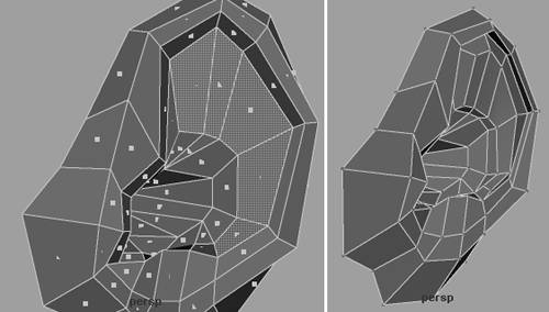
Adjust the vertices to form the ring of the upper ear, and blend the new extrusion with the rest of the ear, as shown on the right in Figure 7.18. On the DVD Chapter_07\ch07tut04end.mb |
Create the forked split edges shown in the left half of Figure 7.19 to create the indentation shown in the Side view photo. Use the Split Polygon tool to create these three separate splits for the upper part of the ear. Figure 7.19. Two polygon split operations to add the indentation shown in the Side view photo. 
Switch to Vertex mode and move the newly created vertices inward to form the indentation. Add an extra split to clean up this area, as shown in the right half of Figure 7.19. Switch to Edge mode and select the outer ring of edges for the ear, as shown in Figure 7.20. The edges near the front of head are not selected. Figure 7.20. Selecting part of the outer edge of the ear. 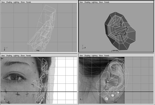
Now, extrude these edges inward to form the back of the ear, as shown in the leftmost image in Figure 7.21. Figure 7.21. Extruding the ear, then merging the ends of the extrusion (the merge is already completed in the figure), and then merging two other pairs of vertices. 
Adjust the vertices so that they form the shape for the back of the ear. Also, merge the first and last vertices of the extrusion to form triangular polygons where the back of the ear starts, as shown in the middle image in Figure 7.21. Merge the two indicated pairs of vertices, as shown in the rightmost image in Figure 7.21. This reduces the detail in the back of the ear so that fewer cuts need to be made to the head to attach the ear.
Tutorial: Making an Attachment Point for the Ear Now that the ear is complete, you'll need to cut a hole in the side of the head to weld this new object. The hole needs to have the same number of edges as the ear's outer edge. On the DVD Chapter_07\movies\ch07tut06.wmv |
Make the head visible by enabling the layer's visibility. Turn on Wireframe on Shaded and X-Ray modes in the Perspective view (choose Shading | Shade Options from the panel menu) so that it's easier to see where splits need to be made to attach the ear to the head. On the DVD Chapter_07\ch07tut05end.mb |
Choose Edit Polygons | Split Polygon Tool to create four new edges on the head, as shown in the left image in Figure 7.22. Create them so that the head has edges positioned for the edges of the ear to connect to. Figure 7.22. Subdividing the head for the ear opening and point-snapping head vertices to the ear boundary. 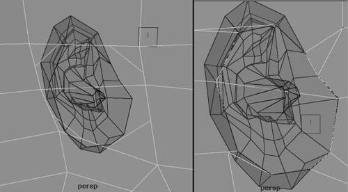
Switch to Vertex mode and point-snap the head's new vertices to the nearest outside vertex of the ear, as shown on the right in Figure 7.22. Switch to Face mode. Select and delete the two unneeded inside faces of the head that are being overlapped by the ear. This creates the hole that the ear will fill. Adjust the head's vertices next to the ear's attachment point so that the four triangles at the corners of the ear point away from the ear diagonally. This helps ensure that faces aren't being distorted too much (this distortion is known as shearing). Move the vertical column of edges directly behind the ear forward along the top of the head to help keep the shape flowing a little better. The edges should flow in a straight line up from the top of the ear (see Figure 7.23). Figure 7.23. Selecting part of the ear's outer edge. 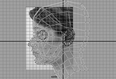
Disable X-Ray mode in the Perspective view. Switch to Edge mode and delete the edges indicated in the leftmost image in Figure 7.24 to get rid of all the triangles in that area. Figure 7.24. Deleting two edges and three sets of splits helps adjust the head shape for the merged ear. 
Use the Split Polygon tool to create the edges indicated in the second image from the left in Figure 7.24. This divides the polygons where the top of the ear connects to the head. It also adds another division for rounding the top of the head. Move each of these vertices outward to add roundness to the top of the head. Use the Split Polygon tool again to create the edges under the ear, as shown in the third image in Figure 7.24. This divides the area where the bottom of the ear connects to the head. As in step 9, pull these vertices slightly outward to add roundness in this area. Because the row of vertices above the ear was moved forward earlier, a new row needs to be created to allow for more roundness in the back of the head. Use the Split Polygon tool to create the edges shown in the rightmost image in Figure 7.24. Then, move the vertices to add roundness to the back of the head.
Tutorial: Attach the Ear and Mirror the Face In this tutorial, you'll connect the ear to the head and do the final mirroring and attachment. On the DVD Chapter_07\movies\ch07tut07.wmv |
Select the head and then Shift-select the ear. Choose Hotbox | Polygons | Combine to make them a single object. Switch to Vertex mode and select all the head's vertices. Choose Hotbox | Edit Polygons | Merge Vertices | option box, and set Distance to a small value, such as 0.0001, so that only neighboring vertices are merged. The ear boundary should now be welded. On the DVD Chapter_07\ch07tut06end.mb |
Exit Vertex mode (hotkey: F8) and mirror the head (Hotbox | Edit | Duplicate | option box). Reset the settings. Set Scale X to 1 and the Geometry option to Instance, and click Apply. The head mesh is apparent now, but has some problems. The face is somewhat gaunt and looks like an old man rather than a young woman. Check the Front viewport, and you'll see that the jawline and other areas of the head need adjustment. Switch to Vertex mode and move the vertices of the cheeks and jaw to reshape the face so that it better matches the current image planes. Use Figure 7.25 as a guide. Figure 7.25. The head after broadening the jawline and accentuating the cheekbones. 
Delete the instanced mirror of the face. Delete the edge shown in Figure 7.26 and then snap and merge the remaining vertex down to its nearest neighbor. This leaves one solid edge running vertically where the right side of the deleted edge connected. Figure 7.26. Delete an edge and merge two vertices to get rid of the horizontal edge break. 
Mirror the head (hotkey: Ctrl+Shift+D). Reset the settings. Set Scale X to 1 and the Geometry option to Copy, and click Apply. You're not using an instance duplicate this time because the head will be welded into a single piece. Combine the two halves of the head into a single object (Hotbox | Polygons | Combine). Right-click over the head and choose Vertex. Merge the vertices (Hotbox | Edit Polygons | Merge Vertices | option box), and set Distance to 0.0001 so that only neighboring vertices are welded together. Click the Merge Vertex button to apply. The head is now a single object. From this point, you must be careful about maintaining symmetry when you work on the head.
Tutorial: Subdivision Surfaces Conversion, Cleanup, and Refinement In this final tutorial, you'll convert the head to Subdivision Surfaces, a fundamentally different type of geometry in Maya. This part has been saved for the end because making adjustments to detailed SubD models can be tedious with the large computational overhead. If you make an adjustment and it takes a few seconds for the computer to catch up and display the change, it might help to delete the object's construction history (Edit | Delete by Type | History). Other factors, such as the speed of your computer and its display card, can affect performance as well. On the DVD Chapter_07\movies\ch07tut08.wmv |
On the DVD Chapter_07\ch07tut07end.mb |
First, to keep a backup of the geometry, make a duplicate of the head (hotkey: Ctrl+Shift+D). Reset the settings and click Duplicate. Put this new head on its own layer (named polyHead) in the Layers dialog box, and then hide the new layer by toggling the V next to the layer name. Clean up the head polygons (Hotbox | Polygons | Cleanup | option box). Make sure the Nonmanifold Geometry check box is selected for cleanup and that the Normals and Geometry option is selected. Convert the model to Subdivision Surfaces (Hotbox | Modify | Convert | Polygons to Subdiv). The head should take on a rounded appearance (see Figure 7.27). You can confirm that it's a SubD object by using the 1, 2, and 3 hotkeys to set the smoothness level. Set the level back to minimum (hotkey: 1) for fast interactivity. Figure 7.27. The head before and after converting to Subdivision Surfaces. 
The head looks good smoothed, but there are obvious problem points, such as creases along the centerline in the forehead and neck. The lines from the nose to mouth corners need to be smoothed, too. To continue editing as before, you need to activate the polygon proxy of the SubD model. This enables you to edit the SubD model's CVs. Right-click on the SubD model, and choose Polygon. After a slight pause, a polygon proxy cage appears on top of the SubD model. Right-click on the polygon proxy cage and choose Vertex. Now, you're editing the SubD model based on the proxy cage approach used in previous tutorials. tip Make sure you have the mesh selected and aren't in Component mode when you try the conversion. note Switching in and out of polygon proxy mode is handled by right-clicking over the mesh. As in the previous step, choose Polygon to enable the cage. When the cage is active, right-clicking over the object changes the menu to display Standard instead of Polygon use this menu to switch back to non-polygon proxy mode. First, you'll work on removing the crease down the center of the face. Right-click over the model and choose Vertex. Above the bridge of the nose, select the centerline vertex and the vertex on each side (see Figure 7.28). Merge them (Edit Polygons | Merge Vertices | option box) and set Distance to 5. Click Apply so that the Merge Vertices Options dialog box stays open; you need to use it for the next steps. Figure 7.28. The first three vertices to merge into one. 
trap All three vertices and only those three vertices must be selected at the same time for step 5 to work. Be careful to check the back of the head after any selection to make sure you haven't accidentally selected vertices on the back side. Select the three vertices above the ones you just merged and merge them, setting Distance to 5 so that the point-snapping step can be skipped. tip Temporarily turning off Subdivision Surfaces in the viewport's display menu (choose Show | SubD from the panel menu to toggle it off) in all four views makes it easier to select vertices obscured by the shaded SubD model. It also helps you complete the operation more quickly because Maya doesn't have to recompute the SubD result each time you change the polygon proxy cage. Repeat step 6 for the next two rows of vertices above the one you just merged. Merge each trio of vertices individually. Repeat for the vertices below the ones shown in Figure 7.28. Go down the nose, merging the four trios of vertices shown in Figure 7.29. Figure 7.29. Merging the nose vertices be sure to merge each horizontal trio of vertices individually. 
Now, you'll work on the nose and forehead. Merging the vertices along the nose changed its shape to a ski-ramp slope in the Side view. The forehead also has a prominent ridge at the centerline. Again, you'll solve the forehead problem by simplifying the mesh in that area. Select and merge the three forehead vertices shown in Figure 7.30 to get rid of the ridge. Figure 7.30. Merging the trio of vertices on the forehead. 
Realign the vertices along the ridge of the nose in the Side view so that the nose takes on the correct shape. Instead of moving the perimeter vertices, use the vertices marked in Figure 7.31 to get rid of the large dent in the nose seen in the Side view. Figure 7.31. Move the marked vertices to get the nose back to a smooth shape. 
Delete the edges indicated in Figure 7.32 to get rid of the triangles and create quads. Figure 7.32. Delete the indicated edges. 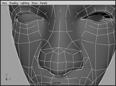
As in step 6, the process of merging vertices to the center is used to merge vertices along the neck to smooth the front of the neck. Merge trios of vertices around the centerline from the front base of the neck up to the last edge at the inside of the lower lips. The chin, neck, and lower lips should now look smooth. Next, you'll adjust the creases from the sides of the nose to the corners of the mouth. Tweak the vertices around this area, aligning the points with the marks drawn on the model's face in the reference image and observing the viewport until the model becomes smooth. Deselect the SubD mesh in the Perspective view periodically to check your results. Figure 7.33 illustrates the changes. Figure 7.33. Bringing vertices forward slightly in the "smile lines" reduces this crease. 
trap At this point, the model is no longer automatically symmetrical, so you must take care if you want to maintain symmetry. Always select vertices that will be adjusted in the Side view by using a marquee selection to get both sides of the face. For moving the vertices in the X-axis, use the Scale tool to move the vertices closer to or farther away from the centerline. Using the same techniques as in step 13, narrow the nose ridge and reshape the nose until it matches the front and side image planes. Exit Polygon mode by right-clicking over the model and choosing Standard. If you have hidden SubD objects from the Perspective view, you can re-enable them now. Then, right-click over the model and choose Edge. Shift-select the edges forming the top of the eyelids, where the brow curves back and connects to the eyelids (see Figure 7.34). This is best done in the Perspective view so that you can tumble the camera to see what you're selecting. Figure 7.34. A set of edges selected to crease the eye fold. 
Choose Hotbox | Subdiv Surfaces | Partial Crease Edge/Vertex to partially crease the selected edges. Repeat step 16 for the other eye. Select the edges going around the rim of the eyelid, leaving the two inner edges of the eye corner unselected (see Figure 7.35). Choose Hotbox | Subdiv Surfaces | Full Crease Edge/Vertex to crease the selected edges. Figure 7.35. The result of creasing the eye fold. 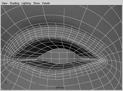
Now, you'll soften this crease slightly by keeping the same edges selected and performing a partial crease (Hotbox | Subdiv Surfaces | Partial Crease Edge/Vertex). Repeat for the other eye. That's it you've created a human head! You now have an idea of what the human head's general topology is and see how to turn a rough lump of polygons into silky smooth, finely detailed SubDs. On the DVD Chapter_07\ch07tut08end.mb |
Going Further If you want to continue improving the quality of this head, you might explore filling out the cheekbone areas. You could also refine the nose more and add subtle dimples at the corners of the mouth. For the more ambitious, you can begin modeling the full body from the base of the neck down. To get the full-body images of this model, go to the book's web site at www.mayafundamentals.com. |
|