| Before you start modeling an architectural project in Maya, you should sketch a rough drawing of what you want it to look like. It's a good idea to make a plan that includes at least top view and side view drawings. Additional drawings can be helpful to illustrate other detail that's easier to see from other angles of view. If you just try to improvise, you'll wind up spending a lot more time correcting errors instead of creating a nice architectural space. Planning ahead by creating drawings helps you progress much faster to the results you want. tip You can scan a sketch of your office entrance and apply the images to an image plane, a bitmap viewer in Maya that's specific to one of the orthogonal views.
Loading an Image for Reference Before you load scans of your architectural sketches in Maya, you need to make sure they're as close to the same size as possible, particularly in height. In this chapter's example, the drawings a top view called the plan view and a side view called the elevation view should be proportional so that you can switch between the two views and maintain the correct proportion while building your model. With this in mind, you should try to sketch both drawings at the same scale so that you can simply scan them, but if you're in doubt, just resize them to match in a bitmap editor (such as Photoshop). For this chapter, the reference images have been supplied for you, so you can load the images into the camera views and begin modeling. trap When saving your image file in Windows BMP format, do not use this format's optional compressed mode. Maya cannot decode BMP image files that have been compressed. Other preferred options for image formats include JPEG (.jpg files) and Targa (.tga files).
Tutorial: Loading Image Planes for Reference Continue from the previous tutorial or load the scene file listed next to the DVD icon. To model your office lobby, you'll start off with floor plans, so first, you'll need to load some reference images. On the DVD  Chapter_05\movies\ch05tut02.wmv |
Right-click on the Top viewport to make it active. To import an image, choose Hotbox | View | Image Plane | Import Image. Insert the Maya 5 Fundamentals DVD, select the file noted next to the DVD icon, and then click the Open button to create imagePlane1. On the DVD  Chapter_05\ch05tut01end.mb |
Open the Attribute Editor for the image (Hotbox | View | Image Plane | Image Plane Attributes | imagePlane1). Change the name of imagePlane1 to floorplan. On the DVD Chapter_05\floorplan.jpg |
In the Attribute Editor, expand the Placement Extras section, and set Width and Height to 18. Confirm that Coverage Origin X and Y are set to 0. Under the Placement section, confirm that Offset is set to 0, 0. Next, in the Image Plane Attributes section, change Alpha Gain to .375. Your model should be semitransparent now, giving you a less obstructed view. (see Figure 5.6). Figure 5.6. With the Attribute Editor, you can load images into your scene and modify how they're displayed. 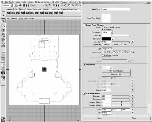
To load the image for the side walls, make the Side view active (right-click on it), and then repeat the procedure used to load the Top view's image, but use elevation1.jpg this time (see Figure 5.7). In the Attribute Editor, change Coverage Origin X and Y to 0. In the Placement Extras section, change the Center settings to -8.8, 8.5, and 0. Name the new image plane leftside, and resize it with the same Width and Height settings you used in step 3. Figure 5.7. The viewports with the image planes loaded. 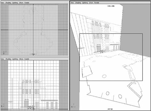
On the DVD Chapter_05\elevation1.jpg |
The reference images are now set up, so you can start modeling your office lobby. The three images should be about the same proportions in the viewports. If not, you can open the Attribute Editor for each image plane and compare them while tweaking settings.
tip At the bottom of the Attribute Editor (hotkey: Ctrl+a) is the Copy Tab button. You can use it to make a floating window that becomes the attribute panel for a specific scene element. You can tear off a tab for one object's attributes, and then open other attributes in the Attribute Editor while still viewing the tab that was "torn off." It's an easy way to compare settings.
Modeling the Walls Whether you're building an environment or a character from polygons, the process is generally the same. Reference images are useful for giving your model a direction and giving you a sound proportional base to begin from. Your next task is roughing out a shell so you can begin adding detail. You'll be using only a few simple tools Split Polygon, Extrude Faces, and Create Polygon to model. As you create the main elements of the environment, try to think in terms of working with key areas of detail. You're going to be slicing and adding to your model by combining polygons. As you work through the modeling process, gradually, the space will take form. If you have difficulty visualizing the steps for creating parts of the environment, you can always refer to this chapter's figures for help. Tutorial: Blocking in the Floors and Walls Continue from the previous tutorial or load the scene file noted next to the DVD icon. On the DVD Chapter_05\movies\ch05tut03.wmv |
Begin in the Top view and maximize the view by pressing the spacebar. To create an accurate work area, start by zooming into the upper-left corner of the floor to begin drawing your polygon shape. Before you trace the outline, turn off the Fast Interaction option (Window | Setting/Preferences | Preferences | Display | Performance). Interactivity will slow down, but this is necessary to keep the image plane visible while tracing it. On the DVD Chapter_05\ch05tut02end.mb |
Using the Create Polygon tool (Hotbox | Polygons | Create Polygon Tool), start in the upper-left corner of the floorplan. Trace the outside perimeter of the floorplan, holding the Shift key down to keep the lines straight (see Figure 5.8). While tracing the outline, don't draw in the doors or windows. When you make it all the way around the perimeter, stay one vertex point away from the corner where you began. Press Enter to close the polygon and exit the operation. Figure 5.8. Trace the floor plan's outline, creating a polygon to match the shape exactly. 
tip Remember to enable the Fast Interaction option after you finish tracing the floor plan (Window | Setting/Preferences | Preferences | Display | Performance, and set Fast Interaction to On). This option speeds your interaction with Maya by freeing up valuable system memory, which is required to constantly redraw background images while the camera is moving throughout the scene. Switch to the Side view. Now, you'll start extruding faces from this new polygon shape. First, select the outlined polygon that matches the floor. Name it Walls, and open the Extrude Face Options dialog box (Hotbox | Edit Polygons | Extrude Face | option box). Set all Translate values to 0 and Divisions to 8, and click the Apply button. When you create an extrusion with Construction History enabled, you'll see a combined translate, scale, and rotate manipulator. Use the manipulator handles in your viewport to pull the height of Walls up to where the side image represents the ceiling. In the Channel Box, Local Translate Z is set to approximately 10.869. Matching the image is more important than the numeric value, so be sure to adjust the height of Walls to match the image. Using the same method you learned in the first polygon tutorial, right-click over the model and choose Vertex. Select the lowest line of vertices and use the translate handle to move this line of vertices into position above the first line of baseboard trim at the bottom of the image. Repeat this process of selecting each line of vertices and moving them over the top of the baseboard trim lines in the image until only the top row is left for the ceiling (see Figure 5.9). Figure 5.9. The top face of the cube has been extruded upward, and the vertices are redistributed to match the image. 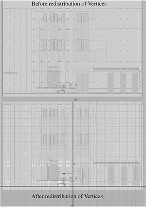
In the Perspective viewport, choose Shading | Shading Options | X-Ray from the panel menu. This option makes objects in your scene semitransparent so that it's easier to see what you're working with. Switch to the Side view, where you'll see dark tan strips of color that represent a half-inch-thick border. Right-click over the model and choose Face. Select only the faces that lie on top of where the image has the tan color to indicate a different material. Next, extrude this set of faces (hotkey: Ctrl+e). Use the extrude handle to pull the faces out slightly. Repeat the step of extruding faces for the line of faces that correspond with the other two dark strips in the image. (Note that these borders are only on the first floor.) As you work through the upcoming edits, be careful not to translate faces in any direction other than pointing toward the center of the room, as shown in Figure 5.10. Figure 5.10. The space in Perspective view after extruding the borders. 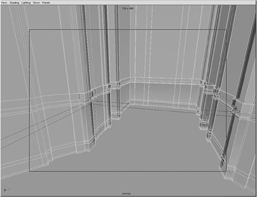
tip Remember that you need to switch out of Component Selection mode (hotkey: F8) or you won't be able to select objects. Component mode confines you to selecting parts of objects, such as endpoints. Between the planters on each side of the lobby is a dark stone waterfall. Select the face on the center of the darker stone region and extrude it (hotkey: Ctrl+e). For the extrusion amount, in the Channel Box, set Local Translate Z to -0.12. Repeat this extrusion on the opposite wall for a second waterfall (see Figure 5.11). Press F8 to exit Face selection mode. Figure 5.11. Extruding faces using the background images as reference. 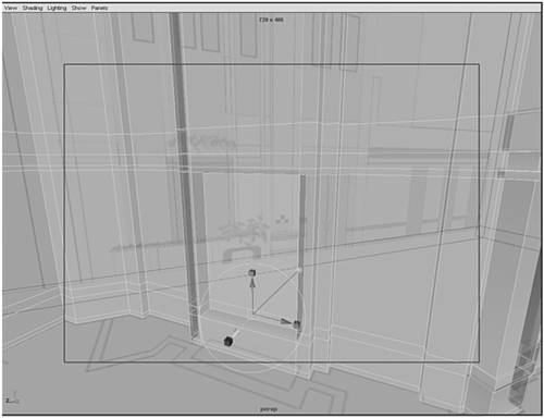
Switch to the Perspective view. In the floorplan image, you'll see an outline for a planter beneath the left-side waterfall. Create a cube and name it Planter. In the Channel Box, set Translate X, Y, and Z to -4.981, 0.357, 2.62; Rotate X, Y, and Z to 0, 45, 0; and Scale X, Y, and Z to 5.386, 1.213, 0.718. Under the Channel Box's INPUTS section, change Height to 1, 0.6, 1 and Subdivisions to 9, 4, 1. These settings position the Planter object on top of the planter image and adjust its size to match the image's planter. Switch to the Side view. Right-click over the planter and choose Vertex. Select each row of vertices, one at a time, and position them over the lines in the image plane on the left. Remember to use only the manipulator handle representing the Y-axis, just as you did earlier to position the borders in the main room. Switch to the Top view. Marquee-select what looks like a single vertex in the Top view. This also selects the vertices beneath it you just won't be able to see them in the Top view. Position these vertices over the image of the planter, moving only the vertices in the room at first. After the basic shape is finished, right-click over the model and choose Face. Marquee-select the bottom row of faces and the top two rows of faces. Extrude the faces (hotkey: Ctrl+e) in the Local Translate Z direction to 0.035. Next, select only the faces on the top row. Extrude again in the Local Translate Z direction to 0.035 to create the lip on the planter's top edge. Switch to the Perspective view, and select the innermost faces. Extrude them inward in the Local Translate Z direction to -0.05 to create an area for dirt and plants (see Figure 5.12). Figure 5.12. In the Perspective view, you can see that the new extrusions have created borders at the front of the planter and an indentation in the top for plants. 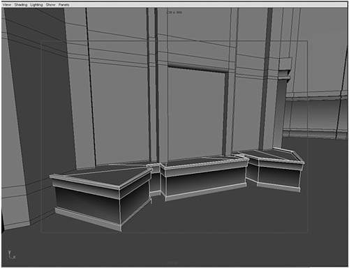
You need to copy a planter to the opposite wall on the right side. Press F8 to exit Face mode, and open the Duplicate Options dialog box (hotkey: Ctrl+Shift+D). In the Duplicate Options dialog box, set the Translate options to 10, 0, 0; the Rotate options to 0, -90, 0; and the Scale options to -1, 1, 1. Leave the default settings of Geometry Type set to Copy and the World option set to Group. No other check boxes should be selected. Click Apply to create the duplicate planter.
Working with Primitives Now, you'll get to model with more solid forms, such as the cube, the cylinder, and the sphere. Deciding ahead of time which basic shapes will work best for the job makes your work easier in the long run. In the upcoming tutorials, you'll begin to model the next two floors, the plant stands, and the lobby furniture. To do this, you'll use some of the techniques you've learned in previous tutorials and explore using beveling and Booleans to add detail and complexity. Although these techniques might seem simple, you can use them to create a level of detail suitable for even the most complex projects. Tutorial: The Upper Floors Continue from the previous tutorial or load the scene file noted next to the DVD icon. On the DVD Chapter_05\movies\ch05tut04.wmv |
To create the second floor, choose Hotbox | Create | Polygon Primitive | Cylinder | option box. Set Subdivision Axis to 20 and Subdivision Height to 3, and select Axis Y. Click Apply. In the Channel Box, name the cylinder floor2, and then set Translate X, Y, and Z to 0, 4.363, -3.244 and Scale X, Y, and Z to 1.861, 1.041, 0.942. On the DVD Chapter_05\ch05tut03end.mb |
Switch to the Side view. Use the background image as reference, and adjust each row of vertices in floor2 to match. The two rows of vertices in the center should match the small indentation shown in the image. Switch to the Top view. Right-click over the model, and choose Vertex. Marquee-select the three vertices to the left (this also selects all the vertices in the row under them) and flatten them with the Scale tool, scaling them on one axis until the three vertices are in line with one another. Repeat this with the three rows of vertices on the right so that both sides of the cylindrical shape are flat. Select the vertices facing the back wall, and scale them on one axis until they are in line (hotkey: r). Use the Z-axis manipulator handle to make sure the scaling is limited to the Z-axis. Switch to Move mode (hotkey: w) to translate the row of vertices near the back wall. Again, use the Z-axis handle to constrain movement in that direction, and move the vertices so that they are just through the back wall. Press F8 to exit Vertex selection mode, and in the Perspective view, select the floor2 object. To make the floor2 object the only object that can be seen in the viewport, choose Show | Isolate Select | View Selected from the panel menu. Right-click over floor2, and choose Face. Select the flattened faces that are facing the side walls. Using the Z-axis handle, extrude the faces away from floor2 and toward the walls (hotkey: e) to create the floor of the second level (see Figure 5.13). In the Channel Box, set Local Translate Z to 2.261, which leaves the floor extending past the walls on each side. However, this won't be a problem because you'll see only the interior of this building. Figure 5.13. Extruding from primitives to build the second floor. 
To build another floor, you'll use the same methods used to build the planters in the previous tutorial. While still in Face selection mode, select the face on top of floor2, and scale it inward (hotkey: r) until it's about the thickness of a wall. Next, extrude this face (hotkey: e) by pulling the yellow manipulator handle inward. For a precise setting, change Local Translate Z to -0.85 in the Channel Box. Now, create a cylinder and name it lightcanister. In the Channel Box, set lightcanister's Translate values to -2.524, 3.333, -3.429 and Scale values to 0.154, 0.154, 0.154. The bottom side of floor2 has 20 recessed lights to provide lighting for the first floor, so you'll need to create duplicates of lightcanister. Switch to the Top view, and use the reference image to duplicate lightcanister into the 20 positions indicated in the reference image. Next, Shift-select all the canisters and combine them into one object (Hotbox | Polygons | Combine). You might find it easier to select the 20 canisters in the Outliner (hotkey: Alt+o). The pivot point for the new combined object has changed. To center the pivot point, use Hotbox | Modify | Center Pivot (hotkey: Ctrl+c). Now, select floor2, and Shift-select the light canisters. To cut the canister shape out of floor2 and create holes where you'll place the light canisters, choose Hotbox | Polygons | Booleans | Difference. Select floor2 and open the Duplicate Options dialog box (Hotbox | Edit | Duplicate | option box). Reset the options from your last use by choosing Edit | Reset Settings. Click the Apply button to duplicate the floor. Then, move it up in the Y-axis (hotkey: w) using the image as a reference, or enter 8.5 for Translate Y in the Channel Box (see Figure 5.14). Figure 5.14. Creating a third floor. 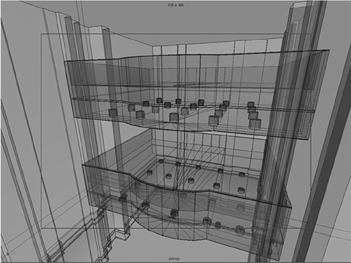
Now that you've finished the two upper floors, you need to add some details for a more realistic look. In architecture, no edges have an exactly 90-degree angle. Edges might look sharp from a distance, but on closer inspection, they reveal a beveled or softer curved edge. Beveling the edges creates subtle differences in shadows and lights, which are two main factors in creating a realistic-looking scene. Switch to the Perspective view, and zoom into the front edge of the floor2 object with the curve in the middle. Right-click over the floor2 object, and choose Edge. Prepare to smooth the top and bottom edges of floor2 by selecting the bottom edge in the front, and then hold down the Shift key and select all the edges that connect around the floor2 object until the entire front edge is selected. Open the Bevel Options dialog box (Hotbox | Edit Polygons | Bevel | option box). In the Offset section, enter .02, and for the Roundness setting, enter .5. For the Segments setting, enter 4 to keep the model light and easy to move around. Click the Apply button. Now, the edge is slightly rounded, as a real corner should be. Repeat this rounding step for the top edge of the wall and then for the top floor. The finishing detail for the upper floors is the small groove set in the front face of both floors. Switch to Face selection mode, and Shift-select the faces positioned toward the interior of the lobby. The other faces are on the outside of the walls, so you can disregard them. Now, extrude the faces (hotkey: e), moving the Z-axis handle until it's inside the floor object, setting Local Translate Z to -0.05. Repeat this step for the third floor (see Figure 5.15). Figure 5.15. Detail grooves to complete the upper floors. 
tip Bevels are based in the scale you're using, and it can take some time to determine the best size. Click the Apply button after entering a setting because this leaves the Bevel Options dialog box open while you're trying different sizes. When you're satisfied with the settings, click OK to close the dialog box.
Tutorial: The Plant Stands Continue from the previous tutorial or load the scene file noted next to the DVD icon. On the DVD Chapter_05\movies\ch05tut05.wmv |
Create a cylinder and name it plantstand. In the Channel Box, set Translate X, Y, and Z to -2.905, 0.345, 6.043. Leave the Rotate settings at zero, and set Scale X, Y, and Z to .285. On the DVD Chapter_05\ch05tut04end.mb |
You'll use the Bevel tool on the top and bottom rings of the plantstand object. In the Bevel Options dialog box (Hotbox | Edit Polygons | Bevel | option box), set Offset to 0.0-2, Roundness to 0.5, and Segments to 4. Switch to the Perspective view, right-click over the model, and choose Face. Select the innermost faces at the top of the planter, and extrude (hotkey: e) them inward by setting Local Translate X to -0.068 in the Channel Box. Deselect plantstand by pressing F8. If the plantstand doesn't look smooth enough, you can use the Smooth Polygon tool (Hotbox | Polygons | Smooth). Set Subdivisions to 1 and click the Apply button to test the smoothness. If one subdivision doesn't look smooth enough, use undo (hotkey: Ctrl+z) to erase your last action and set Subdivisions one level higher. trap Remember to use the Smooth tool carefully increase the Subdivisions setting only in small amounts. Changing the setting in large amounts increases render time and drastically slows down interactivity in the viewports. Switch to the Top view. Notice the plantstand has been positioned over a circle (the plantstand template) on the background image, which corresponds to a certain planter size in the lobby interior. Duplicate this plantstand to all the remaining plantstand templates in the scene. Notice also that under the second and third floors, the majority of circles are dotted outlines. Do not place planters on these locations, because they represent canister lights in the ceilings. You'll also see eight smaller circles representing smaller plantstands. Make one duplicate of the previous plantstand. To scale it to the size of the smaller circles, in the Channel Box, set Scale X, Y, and Z to 0.152 and Translate Y to 0.197. Duplicate this new smaller plantstand and position it using the background image as a reference.
Tutorial: Couches and Lounge Chairs Continue from the previous tutorial or load the scene file noted next to the DVD icon. On the DVD Chapter_05\movies\ch05tut06.wmv |
To begin building the lobby furniture, start by creating a polygon cube. Change Translate X, Y, and Z to 0.14, 0.234, -7.745, keep the Rotate settings at 0, and change Scale X, Y, and Z to 1.684, 0.239, 0.54. In the INPUTS section, set Subdivisions Width to 3 and Subdivisions Depth to 3. On the DVD Chapter_05\ch05tut05end.mb |
Now, apply the Smooth Proxy operation to the cube (Hotbox | Polygons | Smooth Proxy | option box). Set Subdivisions to 2 and click the Smooth button. With the Smooth Proxy object cage active, you can begin moving the cage vertices into position in the Top view. Select the two inner sets of vertices. Scale them out, away from the narrow ends (hotkey: r), using the scale manipulator handle in the X-axis (see Figure 5.16). Figure 5.16. Scaling equal rows of vertices away from each other. 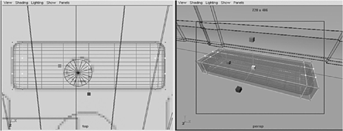
Now, select the two rows of vertices running across the center of the box. Scale these two rows from the center toward the edges using the scale handle in the Z-axis. Right-click on the cage, and choose Face. Select the faces on top of the couch that have been pushed out to the edge. Extrude them slightly (hotkey: Ctrl+e). In the Channel Box, set Local Translate Z to 0.05. Extrude the faces that are still selected from step 5 again, setting Local Translate Z to 0.15. With the basic shape set, press F8 to exit Face selection mode. Hide the Proxy mesh layer by clicking on the V in the Layers dialog box. Click on the Smooth Proxy mesh where "R" is marked to make the smooth version of the couch active. Now, you need legs for the couch. To maintain the streamlined furniture style used in this lobby, create a cylinder and name it couchleg1. Set Translate X, Y, and Z to -0.572, 0.065, and -7.578. Under INPUTS in the Channel Box, set Height to 2, Subdivisions Axis to 8, and Subdivisions Height to 4. Switch to the Front view, and center the view on the selected couchleg1 object (hotkey: f). Right-click on the couchleg1 object, and choose Vertex. Begin scaling vertices in the first row from the top. Select the next row down, and scale it until the leg tapers slightly. Switch to the Top view. To create the two lounge chairs, just duplicate the couch (hotkey: Ctrl+d), and name the new object chair. Change Rotate Y to 90. Set Translate X, Y, and Z to -1.04, 0.234, -7.134 and Scale X, Y, and Z to 0.52, 0.239, 0.54. Repeat step 10 for the second chair, but change Rotate Y to -90. Duplicate couchleg1 11 times (hotkey: Ctrl+d) and move each copy into position under the four corners of the couch and under the two lounge chairs. To complete the lounge area, you need a coffee table. Create another cylinder and name it table. In the Channel Box, set Translate X, Y, and Z to 0.116, 0.199, -6.855 and Scale X, Y, and Z to 0.337, 0.112, 0.337. As you did with the planter, right-click over the model, and choose Edge. Select the edges that create the top and bottom edges of the cylinder. Next, bevel those edges (hotkey: b) to give the table a softer-looking edge. For the table's bevel, set Offset to 0.02, Roundness to 0.5, and Segments to 4. Now, duplicate the legs under the lounge chairs and place them under the coffee table (see Figure 5.17). The height for both sets of legs is the same, but the table legs can be adjusted more, if you like. Figure 5.17. Simple furniture for the lobby. 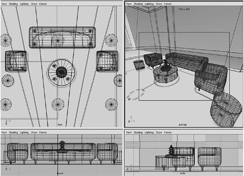
Tutorial: The Doors and Handles To finish the scene, you'll need doors at the entrance and at several locations on each side as well as three elevator doors near the back. Continue from the previous tutorial or load the scene file noted next to the DVD icon. On the DVD Chapter_05\movies\ch05tut07.wmv |
Switch to the Side view. Right-click over the model, and choose Vertex. Select the vertical row of vertices on the left side of the glass doors in the image plane, and move the row in the Z-axis until the row lines up with the edge of the doors in the reference image. On the DVD Chapter_05\ch05tut06end.mb |
Switch to the Front view, and position your cursor where the doors are indicated in the reference image. Select the Split Polygon tool (Hotbox | Edit Polygons | Split Polygon). You'll use this tool to draw a line, starting where the top of the doorway should be. First, click on the edge of the recessed portion of the wall. Before clicking on the other side of the polygon face, position your view so that you can see the opposite side clearly. After you click on the other side of the polygon face and a line connects the two edges, press Enter to end this operation. To reactivate the last tool (Split Polygon), use the hotkey y. The cursor changes to a small arrow. Use the tool again to create another split on the polygon face just above the last split. Press Enter to end the operation. Right-click over the wall, and choose Face. Marquee-select the faces in the doorway. Be sure to select only the faces beneath the last split made in step 3. Move the faces back, using the manipulator handle in the X-axis, until they create a space deeper than the width of the door opening (see Figure 5.18). Figure 5.18. Splitting polygons to create doorways into a side office. 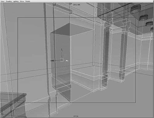
Now, create a cube for the glass door (hotkey: Shift+C). In the Channel Box, set Translate X, Y, and Z to -3.335, 1.273, and -0.904 and Scale X, Y, and Z to 0.03, 2.476, and 0.713. Duplicate the glass door (hotkey: Ctrl+d) and adjust Translate Z to 0.713. All other values remain unchanged. Now, you need door handles for the door. Create a cylinder, setting Translate X, Y, and Z to -3.263, 0.81, and -1.341 and Scale X, Y, and Z to 0.012, 0.174, and 0.012. Under the INPUTS section, set Subdivisions Axis to 12 and Subdivisions Height to 7. Switch to the Front view. Right-click over the model, and choose Vertex. Begin moving each horizontal row of vertices upward from the center. You should now have four rows of vertices at the top of the cylinder and four at the bottom. Select the top three rows of vertices and rotate them in the X-axis about 30 degrees. Now, position the vertices using the Move tool (hotkey: w) so that they're halfway between the body of the cylinder and the glass door's surface on the left. While holding down the Shift key, marquee-select just the selected row of vertices closest to the center of the cylinder to deselect them. Be careful not to begin the marquee window within the Rotate manipulator, because you could accidentally rotate the vertices. Now, you should see only two rows selected. Repeat step 10 on the next row. The last row can be positioned just within the glass door's surface at a 90-degree angle. Repeat this for the lower section of the cylinder. Name the cylinder doorhandle and duplicate it. Set its Translate Z to -1.175 (see Figure 5.19). Figure 5.19. Glass doors and handles made from cylinders. 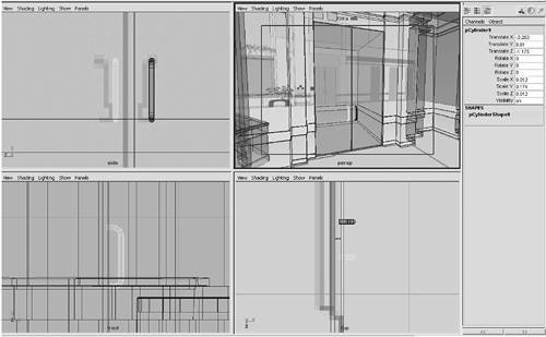
Duplicate the doorhandle object. Now, you can rotate these handles 180 degrees in the Y-axis and move them into position on the other side of the door. Select both handles, duplicate them, and move them over to the right-side door so that they're in a mirror image of the originals' position on the left-side glass door. Select both doors and both handles. Group them (hotkey: Ctrl+g), and name them glassdoors. Duplicate the glassdoor group and move the resulting glassdoor1 group to the front entrance. In the Channel Box, the values should be about 3.292, 0, 8.595 for Translate X, Y, and Z and 90 for Rotate Y. For the remainder of the front entrance, select glassdoors1 and duplicate it (hotkey: Ctrl+d). Move the resulting glassdoors2 into position over the reference image in the Top view. The Translate Z value should change to 9.882. Now, it's time for the walls of the front entrance vestibule. Create a cube (hotkey: Shift+C), and set its Translate X, Y, and Z values to 1.384, 1.276, 8.012 and its Scale X, Y, and Z values to 0.022, 2.506, 1.316. Under the INPUTS section, change Subdivisions Depth to 3. Right-click over the model, and choose Vertex. Scale the center vertices in the Z-axis away from the center. You should see the vertices line up with the inner wall displayed in the reference image. Switch to the Perspective view. Right-click over the model, and choose Face. Select the two thin faces you just created, and extrude them (hotkey: Ctrl+e) toward glassdoors1 until the Local Translate Z value is 0.641 in the Channel Box. Press F8 to exit Face selection mode. Name the new glass walls vestibule. Duplicate the vestibule (hotkey: Ctrl+d), and move it to the opposite side, using these settings: Translate X, Y, Z to -1.372, 1.276, 8.012 and Rotate X, Y, Z to 0, 180, 0. tip When using the Face, Vertex, and Edge selection modes, you might find it easier to maximize the viewport and zoom in tighter to select and move items with precise details. Notice that the wall runs through your entrance at this point. Right-click on the wall, and choose Face. Select any faces inside the vestibule, and delete them. You might need to use the Split Polygon tool if the faces don't line up with the vestibule's walls. For the last piece, you'll need a roof for the entrance. Create a cube (hotkey: Shift+C). In the Channel Box, set Translate X, Y, and Z to 0, 2.671, and 8.076; Scale to 2.84, 0.308, 1.829; and Subdivisions Depth to 3. Switch to the Side view. Right-click over the model, and choose Vertex. Then, adjust the vertices using the background image as reference (see Figure 5.20). Figure 5.20. Creating the front entrance vestibule. 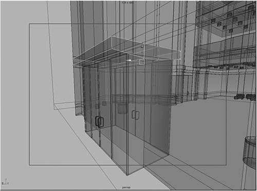
As your final step, use the Outliner to select similar objects and group them. Give those groups descriptive names and remove any empty or unnecessary nodes. If you like, you can compare your finished scene to the one noted next to the DVD icon. You've created an architectural environment in some detail. Using a mix of repeated edits to a polygon cage, you have added surface detail where needed and fleshed out the main space with several elements to add scale. As you might guess, creating the rest of the lobby involves a similar process, combining splits, extrudes, and edits in a method that's a bit like sculpting. Best of all, you can increase the level of detail and add beveled edges to many surfaces, yet still have a fairly low polygon count that allows for a high degree of interactivity in the Maya OpenGL display. This gives you fast interaction for animating and helps reduce complexity when it's time to texture, light, and render the space. On the DVD Chapter_05\ch05tut07end.mb |
Going Further You'll find that your model still needs a lot of work to seem like a real environment, but attention to lighting and texturing can make a less detailed model seem real. An extra step you could take to add more detail is to use the techniques you've learned so far to add several large panes of glass near the front and rear windows. Later in this book, you'll learn how to apply textures in Chapter 9, "Materials," and add lighting in Chapter 10, "Lighting." After you successfully create this environment in detail, consider creating another environment, perhaps something you've drawn, and attempt to model it with polygons. |
|