Transforming Objects
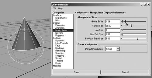
| An object's "transform" sounds like it should mean its position, but it actually describes three functions: position, rotation, and scale. Each function has three components for X, Y, and Z so the transform is made up of nine variables. When you create a scene entity, its transform appears in the Channel Box. You change an object's transform with the Move, Rotate, and Scale buttons in the Tool Box. More often, you'll use the hotkeys for these modes: w, e, and r. When you're changing any of these three transform types, a manipulator appears that enables you to modify the object's position, rotation, or scale constrained to one axis at a time. The axis you are adjusting on turns yellow to indicate the constraint. If you click at the center of the manipulator, you can adjust on all three axes at once. The manipulator's handles appear in three colors: red, green and blue. These colors correspond with X, Y, and Z. It's easy to remember: X-Y-Z, R-G-B. Say it three times. tip Sometimes, you might find that the manipulator handles are too small or large for your liking. You can adjust their size easily with the + and keys. If you want more control over the exact size and appearance, edit this setting by choosing Window | Settings/Preferences | Preferences on the menu. In the Categories list under Display, click Manipulators to open their settings (see Figure 3.6). Here, you can adjust the manipulators' global scale, handle size, and other helpful attributes. Figure 3.6. Adjusting the size of the manipulators in the Preferences dialog box.
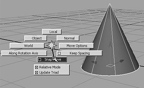
Using TransformsWhen you are in the Move (hotkey: w), Rotate (hotkey: e), or Scale (hotkey: r) mode, you have several options for transforming the object, described in the following sections. Generally, if you click and drag on the surface of a selected object, or on the center point for the manipulator handles, you can freely move or rotate the object. In Scale mode, the object scales uniformly. You can also click and drag on any of the handles to have the action constrained to that axis. The Move ToolClick-dragging on the center point in the middle of the manipulator moves the object in relation to the screen, and click-dragging on one of the axis arrows moves the object along that axis. Clicking on one of the axis arrows selects it, and an MMB-drag anywhere in the viewport causes the object to move along that axis. Ctrl+clicking on an axis arrow changes the center point to be constrained to a plane perpendicular to the selected axis. For example, if you Ctrl+click on the Y axis, and then click+drag in the center point, your translation is constrained to the X-Z (ground) plane. A little yellow plane appears at the center of the manipulator to indicate the plane that movement is constrained to. Normally, this yellow indicator faces the viewer and looks like a square, indicating screen-relative movement mode. If you are in planar movement mode, Ctrl+clicking on the center point resets it to screen-relative movement. MMB-dragging in the viewport moves the object in relation to the current settings for the center point. You don't have to select the object or center point of the manipulator to move the object; any part of the viewport will work. For example, if you have just moved the object in one direction, that arrow remains yellow, and MMB-dragging anywhere in the viewport moves the object constrained to that axis. Shift+MMB+drag moves the object along the axis that most closely aligns to the drag direction. You don't have to click on the object or the manipulator to do this; again, anywhere in the viewport will work. By aligning the drag direction to one of the three XYZ axes, you can move the object on that axis. This is the most efficient way to quickly move objects constrained to one axis. Move SnappingIf you double-click on the Tool Box icons for move, rotate, and scale, you get options for the tools (none appear for scale, but at least an empty dialog box appears). A useful option in this dialog box is snap spacing. You can enable snapping so that the object moves in discrete increments, and you can set the spacing of those increments. To easily enable or disable snapping and other move options, use the marking menu that appears when you hold down the Move hotkey (w) with the LMB, as shown in Figure 3.7. Figure 3.7. The move options marking menu appears when you hold down the w key and click the LMB.
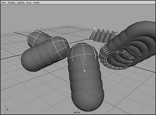
The Rotate ToolClick-dragging on the outer blue ring rotates the object in relation to the screen, and click-dragging inside the manipulator produces free rotation. Click-dragging on a particular rotation axis constrains the rotation to that particular axis. When an axis or the outer ring is selected, MMB-dragging in the viewport constrains the rotation to that axis. Rotation SnappingIn the rotate options, you can find the option to set snaps, which is helpful when you want to rotate objects in discrete increments. A good setting might be 15 degrees to make it easy to rotate objects to precise 30-, 45-, 60-, and 90-degree positions. Note that this snapping happens only when you use a manipulator's axis handle. Rotation options also appear with a marking menu when you press the e key and hold down the LMB. This makes it easy to toggle snapping and other options. The Scale ToolClick-dragging on a particular scale axis constrains scaling to that axis, and click-dragging on the center of the manipulator constrains rotation to all three axes for uniform scaling. After a manipulator axis has been selected, MMB-dragging in the viewport constrains the scale to that axis. Transforming Multiple ObjectsWhen you have selected multiple objects, you can apply transforms to them together. For Move and Rotate mode, revisit the tool options so that you can choose whether your changes happen to the objects locally or globally. For example, after you rotate an object, if you add another object to the selection and move them in local mode along the Z axis, each object moves along its local Z axis completely different directions, as shown in Figure 3.8. Global mode movement forces them all to move together as though they were one object. Double-click the Move button in the Tool Box to switch between modes. Figure 3.8. Movement along the Z axis means something different to each sphere when moving in local mode.
|
EAN: 2147483647
Pages: 198