Chapter 1 - Router Basics

  Chapter 1: Router Basics  
  Objectives  
  The objectives of this chapter are as follows:  
    Explain the role of a router in an internetwork.  
    Discuss how a router is both similar to and different from other network computing devices.  
    Introduce the Cisco router user interface.  


Router Concepts  
  This section introduces router technology and its responsibility in an internetwork, an accepted networking industry term for a set of many interconnected networks. Each individual network will have its own network number that must be unique for that particular internetwork. If some of the terms used here are unfamiliar, don't worry; all the ideas presented in this overview are discussed in more detail and explained fully in later chapters.  
  Routers direct traffic through an internetwork, based on information learned from network protocols. Let's discuss some of the goals of these computer network protocols.  
  With an internetwork that has hundreds or even thousands of computers linked together, there has to be some agreed-upon way for those devices to address one another and communicate. As a network grows larger, it is not feasible for each computer to keep track of the individual address of every other computer on the internetwork. There must be some scheme for reducing the amount of information each computer has to hold locally in order to communicate with every other computer.  
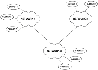
  The scheme used involves splitting an internetwork into many discrete but connected networks, which may themselves be split into subnetworks (Fig. 1-1). The job of keeping track of these discrete networks is then given to specialized computers called routers. Using this method, the network computers need only keep track of the networks on the internetwork, rather than keeping track of every network computer.  
   
  Figure 1-1: Interconnection of networks and subnetworks on an internetwork  
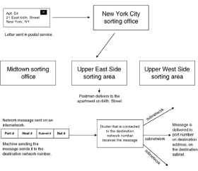
  The best analogy I can think of for describing how computers on an internetwork address each other is the postal service. When you address a letter, you provide an apartment number, street name and number, town, and state. In computer terms, messages are delivered by application port number, host number, subnet number, and network number (Fig. 1-2). These terms will be discussed fully in subsequent sections.  
   
  Figure 1-2: Comparing the Postal Service to an internetwork addressing scheme  
  The key concept is that when the postal service receives a letter for delivery to another town, the first thing postal workers do is to send it to the distribution office in the destination town. From there the letter goes to the people that deliver for that particular street, and finally, the letter is delivered to its destination.  
  Computer networks follow a similar process. The message sent on the internetwork initially gets sent to a router that is connected to the destination network number. This router, in effect acting as a distribution center for this network, will send the message out on the destination subnet number, and finally the message is delivered to the destination port number in the destination machine.  
  Figure 1-3 shows a simple internetwork with routers connecting different network numbers. In this figure, networks 1, 2, 3, and 4 have hosts on them and networks 5, 6, and 7 do not. Networks 5, 6, and 7 are there purely to connect the routers over a local or wide area network. In this internetwork, hosts X and Z must be configured for the same network number (in this case, 2). In addition, the router interfaces that are connected to the same network (for example, interface 2 on router C and interface 1 on router A), must be configured for the same network number (in this case, 5).  
   
  Figure 1-3: Simple internetwork connectivity  
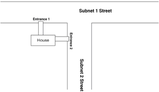
  Using the postal service analogy again, routers that are connected to two networks can be thought of as houses that have entrances on two streets. In Fig. 1-4, we see a house that has two entrances, one on Subnet-1 Street and the other on Subnet-2 Street. Both the address on Subnet-1 Street and the address on Subnet-2 Street are good for purposes of delivering a letter to the house. This is analogous to a router being connected to two network numbers. In Fig. 1-3, the address for interface 1, interface 2, or interface 3 is good for delivering a message to router A.  
   
  Figure 1-4: Illustration of multiple addresses reaching the same location  
  Routers by their very nature seek to route packets from one network number to another. This statement has two immediate practical implications for us. First, you cannot configure the same network number on more than one interface on a router. (Much later we will cover the case in which subnet masks allow the same network number, but different subnet numbers, to be configured on different interfaces on the same router.) Second, because a broadcast has a destination network number, a router does not forward broadcasts by default. (Again, we will discuss later how a router can be configured to forward broadcast packets).  
  Routers Compared to Bridges  
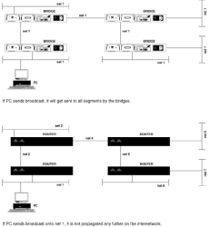
  Routers typically are used to connect geographically dispersed networks together, and to make feasible connecting a large number of computers together. Before routers became popular, bridges often were used to achieve the same goals. Bridges were good for small networks, but had problems working in larger environments. Bridges keep track of all the individual computers on a network. The problem with using bridges to connect large numbers of computers together is that bridges do not understand network numbers, so any broadcast generated anywhere on the network gets sent everywhere. The difference between how routers and bridges handle broadcasts is illustrated in Fig. 1-5.  
   
  Figure 1-5: Illustration of how routers and bridges handle broadcasts differently  
  Many PC networking systems make extensive use of broadcasts, which leads to bridged networks having significant amounts of their usable bandwidth consumed by broadcasts.  
  At this point, it is worth contrasting the routing decisions made by routers and typical workstations or hosts on an internetwork.  
  A typical workstation (a PC running a popular TCP/IP stack, for example) will require some manual configuration before it can operate on a TCP/IP network. At a minimum, you will have to configure an IP address, a subnet mask, and a default gateway.  
  The routing decisions of a workstation configured in this manner are simple. If the workstation has to send a packet to another machine that is on the same network number, the packet is sent directly to the destination machine. If the destination is on a different network number, the packet is forwarded to the default gateway for routing through the internetwork and on to the final destination.  
  Routers make more complex decisions. They must know how to get to all other network numbers on the internetwork and the best way to route the packets, and they need to keep track of an internetwork topology that is constantly changing due to equipment or other failures. To execute these responsibilities, a router maintains a routing table, which lists all the known network numbers and how to get to them. Routers also use routing protocols that keep the routing table accurate for a changing internetwork.  
  Routers Compared to Other Computers  
  Now let's look at how a Cisco router is similar to and different from other computers on an internetwork. A router is similar to other computers in that it has memory, an operating system, a configuration, and a user interface. (In Cisco routers, the operating system is called the Internetwork Operating System, or IOS, and is proprietary to Cisco.) A router also has a boot process similar to other computers in that bootstrap code is loaded from ROM, which enables the machine to load its operating system and configuration into memory.  
  What makes a router different from other computers is the user interface and the configuration of memory.  
  Router Memory Types.     Typically a DOS or Unix system has one physical bank of memory chips that will be allocated by software to different functions. Routers have separate banks of memory, each dedicated to a different function. The function of these memory banks also differs between routers. An overview of the function of router memory types is presented in Table 1.1.  
  ROM.     Read-only memory (ROM) contains a copy of the IOS that the router is using. The 7000-series routers have ROM chips on the route processor board. The 4000 has ROM chips on the motherboard. In the 7000 and the 4000, the ROM chips can be upgraded to contain new versions of IOS. In the 2500 router and 1000-series LAN extender, the ROM chips cannot be upgraded and contain a very limited operating system, just enough to make the router operational. The IOS for a 2500-series router is contained in what is known as flash memory.  
  Table 1.1: Summary of Router Memory Details  
 
 
  Type of Memory  
  7000  
 
  4000  
 
  2500  


  ROM  
  Upgradeable IOS  
 
  Upgradeable IOS  
 
  Non-upgradeable basic OS  
 
  RAM Shared  
  Storage Buffers  
 
  Storage Buffers  
 
  Storage Buffers  
 
  RAM Main  
  IOS loaded from Flash, plus route tables and other data structures  
 
  as 7000  
 
  Routing tables and other IOS data structures only  
 
  Flash  
  Contains IOS  
 
  Contains IOS  
 
  Contains IOS (Router runs IOS from flash)  
 
  NVRAM  
  Config files  
 
  Config files  
 
  Config files  
 
  Note: Because the 2500 series runs its IOS from flash memory, a 2500 might not have enough memory in it to have the IOS upgraded while the router is running. In the 7000 and 4000 series the IOS is running in main RAM; therefore flash can be upgraded while the router is running.  
 
 
  If you are running a version of Cisco IOS earlier than version 11, you will see one unnerving feature of the 2500 series if you attach a terminal to the console port during boot-up. The ROM IOS checks the configuration file and will not recognize most of the commands. This results in many error messages being reported to the screen. This is normal operation. When the IOS in flash memory loads, normally no error messages are displayed.  
  RAM.     Random access memory (RAM) is split by the IOS into shared and main memory. Main memory is used to store router configuration and IOS data structures relevant to the protocol being routed. For IP, main memory is used for such things as holding routing tables and ARP tables; for IPX, main memory holds SAP and other tables. (These terms are explained later.)  
  Shared memory buffers packets waiting to be processed. This type of memory is only used by 4000- and 2500-series routers. The 7000 routers have a switch processor that controls the flow of packets through the router.  
  Flash Memory.    Flash memory holds the current version of IOS running on the router. Flash memory is erasable memory that can be overwritten with newer versions of the IOS unlike ROM, which is located in physical chips that cannot have their contents overwritten.  
  NVRAM.     Nonvolatile RAM (NVRAM) does not lose its contents when the router is switched off. NVRAM holds the router configuration.  
  Booting a Router.     Routers boot up in a similar fashion to PCs; the procedure is as follows:  
  1.   Load bootstrap program from ROM.  
  2.   Load operating system (IOS, the Internetwork Operating System) from flash memory.  
  3.   Find and load configuration file in NVRAM or on a prespecified network server. If no configuration file exists, the router enters setup mode.
 
Getting to Know Your Router  
  This section explains connecting a terminal to a router, understanding the Cisco user interface, and executing basic Cisco commands.  
  Connecting a Terminal to a Cisco Router  
  The discussion here uses connection to a Cisco 2500-series router as an example. Throughout this section, it is assumed that the router to which you are connecting has already received a basic configuration. A later section will cover configuring a router from scratch.  
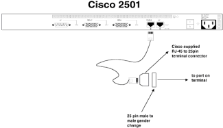
  Figure 1-6 shows the connections that we need to make at the rear of a 2501. Each router will come with a console connection kit, which comprises a black RJ-45 cable and an array of connectors. To connect a Wyse or other standard ASCII terminal as the console, do the following:  
  1.   Connect the RJ-45 cable to the console port on the back of the router.  
  2.   Connect the 25-pin attachment labeled "terminal" to the other end of the RJ-45 cable.  
  3.   Connect a male-to-male gender changer to this 25-pin connector.  
  4.   Connect this 25-pin attachment to the Wyse port.  
   
  Figure 1-6: Router console port to ASCII terminal connections  
  A gender changer is needed because many ASCII terminal providers supply only female connectors on their terminals.  
  If you want to connect your router to a PC and run a terminal emulator of some kind, life is easier. Most PCs come with 9-pin serial port connectors, so just connect the 9-pin serial connector to the RJ-45 cable and link the router console port to the PC serial port. As long as you set your terminal emulation program to 9600 bps, with 8 data bits, no parity, and 1 stop bit, you should be okay.  
  The Cisco User Interface  
  A large part of this text will be devoted to entering configuration, reporting, or other commands, and viewing the router's responses. To do this efficiently in practice, it will help you to know how the Cisco user interface works. Think of this as similar to learning DOSKEY in the PC world or the vi editor in the Unix world. It's important to know at the beginning that you do not have to type in the entire command for the router to know what to do for you. As long as you type enough to identify a unique command, the router will accept it. Here's an example:  
  Hostname#wri t  
  This is the abbreviation for the command write terminal; the string wri t is enough information for the router to interpret the command correctly, and, as we shall see later, this command will cause the router to display its configuration to the screen.  
  Assuming you have connected a terminal to the console port of a previously configured router, you will be presented with a password or router prompt. After entering an appropriate password, if necessary, the display will look something like this:  
  Hostname>  
  At this stage, we can start to enter commands. In the Cisco user interface, there are two levels of access: user and privileged. The first level of access that allows you to view router status is known as user EXEC mode.  
  The privileged mode is known as privileged EXEC mode. This mode is needed to view router configuration, change configuration, and run debugging commands. Privileged EXEC mode often is referred to as Enable mode because, in order to get into privileged EXEC mode, you have to enter the enable command followed by an appropriate password. This is achieved as follows:  
  Press the Enter key  
  password:Supply the Enable password, then press Enter  
  Hostname#  
  The visual evidence that you now have Enable privilege is that the command prompt has now changed to a # character alone.  
  Before we proceed, you also need to be aware that the router can be in one of two modes. The first is what I will term view mode. With this mode, you can enter the show and debug commands. This allows you to view the status of interfaces, protocols, and other items related to the router. It is the mode that the router will be in after you first log on. The second is configuration mode. This allows you to alter the configuration running in the router at that time. This is important to realize, because as soon as you press the Enter key after entering a configuration command, that command takes immediate effect even before you leave configuration mode. You can get into configuration mode only after gaining Enable privilege. This is achieved as follows:  
  Press Enter  
  Enter configuration commands, one per line. End with Ctrl/Z.  
  Hostname(config)#  
  Note that the line telling you to end with Ctrl-Z is echoed back by the computer. The command to get into configuration mode in this case tells the router that it is to be configured from the terminal. The router also can be told to get its configuration from a network server; this will be covered later. You will notice that the prompt changes to remind you that you are in configuration mode.  
  The following is an example of how to enter configuration commands for the Ethernet 0 interface:  
  Press the Enter key  
  Hostname(config-int)#  
  To move back one level, type in the following:  
  Press the Enter key  
  Hostname(config)#  
  If you wish to exit configuration mode from any level, simultaneously hold down the Ctrl and press the Z key:  
  Press the Enter key  
  Hostname#  
  To exit Enable mode, type in the following:  
  Press the Enter key  
  Hostname>  
  You now have the basics for navigating the user interface.  
  Shortcuts.The following lists the more useful of the available keystrokes for the Cisco IOS. If <Ctrl-x> appears, it means you should hold down the Ctrl while pressing the character x key.  
  Arrow Keys.     The arrow keys are useful only with an ANSI/VT100-emulating terminal. The up and down keys display the command history; for example, pressing the up arrow will display the previous command. By default, 10 commands are kept in the history. If you want to change that, go into configuration mode and type in terminal history xx, where xx is the number of commands to remember. The down arrow key will go forward in the command history.  
  If you are not using an ANSI/VT100 terminal or emulation, the command history can still be accessed by using the <Ctrl-N> and <Ctrl-P> key combinations, for Next and Previous command in the command history.  
  Backspace or DEL.     Either of these keys deletes the character before the cursor.  
  Tab or Enter.     Each of these keys executes the command entered.  
  The ? Key.     Possibly the most useful key in the user interface, the "?" key, can be entered at any time to find out what can be entered next. This is best illustrated with an example:  
  Hostname>show ip route ?  
  Press the Enter key  
 
  bgp  
  Border Gateway Protocol  
 
  Connected  
  Connected networks  
 
  egp  
  Exterior Gateways protocol  
 
  eigrp  
  Enhanced Interior Gateway Routing Protocol  
 
  igrp  
  Interior Gateway Routing Protocol  
 
     
  ISO is-is  
 
  ospf  
  Open Shortest Path First  
 
  rip  
  Routing Information Protocol  
 
  static  
  Static routes  
 
  summary  
  summary of all routes  
 
  supernets-only  
  show supernet entries only  
 
  Hostname>show ip route  
     
 
  After the question mark is entered, the router informs you of the options available to complete the command, and re-enters the command typed in so far, so that all you need to do is select the appropriate option. As soon as you see a <cr> option in the available command listing, you know that you can press the Enter key and the router will execute the command.  
  A point to note here is that if the list of options extends past one screen, the last line of the display will show More. Pressing the keyboard space bar will show the next page of information, and pressing the Enter key will show the next single line of information.  
  The following key combinations illustrate useful commands:  
    <Ctrl-A>
Move cursor to beginning of line.  
 
    <Ctrl-B>
Move cursor back one character.  
 
    <Ctrl-D>
Delete the character the cursor is on.  
 
    <Ctrl-H>
Same as backspace, i.e., delete the character before the cursor.  
 
    <Ctrl-K>
Delete characters to end of line. The characters are held in a buffer and can be recalled for later insertion in a command line.  
 
    <Ctrl-U>
Delete to end of line; again, the characters go to a buffer.  
 
    <Ctrl-V>
Used to insert control characters in the command line. It tells the user interface to treat the next character literally, rather than as an editor command.  
 
    <Ctrl-W>
Delete the previous word.  
 
    <Ctrl-Y>
Paste the character from the buffer (same as the yank command in Unix).  
 
    Esc <
Show the first line from the history buffer.  
 
    Esc >
Show the last line from the history buffer.  
 
    Esc b
Move cursor back one word.  
 
    Esc d
Delete the word in front of the cursor.  
 
    Esc f
Move the cursor forward one word.  
 
    Esc Del
Delete the word before the cursor.  
 
  Many administrators with either a PC or UNIX background ask about a full-screen editor within the IOS for altering configuration. This is unlikely ever to be available. A full-screen editor within the IOS raises questions of when command syntax is checked, at what time the changed configuration takes effect, and so forth. Once you are familiar with the user interface, it does seem efficient and simple to use. In Chapter 3 we'll look at how a full screen text editor can be used to edit an ASCII file, which can then be loaded via a TFTP server on to a router. The router configuration files are stored as ASCII. This is particularly useful if you have multiple routers to configure, each needing a similar configuration.
Summary  
  This chapter looked at the role of a router in an internetwork, and contrasted that with the operation of other network devices, such as PCs and bridges. We also saw how to connect a terminal to the console port of a router, so that the basics of the Cisco user interface could be explored.


Cisco TCP/IP Routing Professional Reference
ISBN: 0072125578
EAN: 2147483647
Year: 2005
Pages: 11

flylib.com © 2008-2017.
If you may any questions please contact us: flylib@qtcs.net