The Enterprise: Managing the VPN
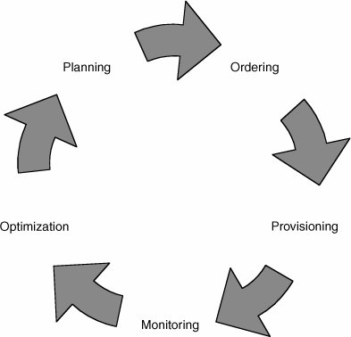
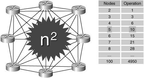
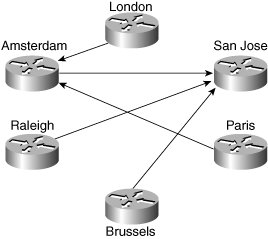
| This section focuses on providing the network manager with information and guidelines to help him or her prepare for the introduction and subsequent management of an MPLS VPN service. Figure 8-5 shows a life-cycle model to be used for reference within this section. Figure 8-5. VPN Life-Cycle Model PlanningAn important part of the network manager's responsibility is ensuring availability of network resources and performance to meet end-user needs. To do this, it is essential to establish a profile or baseline. Another reason why a profile is useful is because it allows the network manager to plan a monitoring strategy between locations. It is good practice for enterprises to test reachability between key locations. This can be used to validate SLAs and also provide fast detection of connectivity problems. In a large enterprise with many sites, however, it may simply be impractical to monitor in a full-mesh style, as shown in Figure 8-6. Figure 8-6. Full-Mesh VPN Monitoring As shown, the number of probe operations increases proportionally to the square of the number of sites. This can be problematic from a management perspective, because it takes up resources on the CE routers and can be difficult to maintain as the network grows. A better approach for large networks is a partial mesh, as shown in Figure 8-7. Figure 8-7. Partial-Mesh VPN Monitoring In this system, specific critical paths are monitored, such as branch office to headquarters or remote site to data centers. This can dramatically reduce the number of probes, as well as management and performance overhead. OrderingEvolving business requirements will require changes to the VPN service. Such changes might take the form of new sites, changes to routing tables/protocols, and decommissioning of sites and circuit upgrades. It is good practice to agree to a moves/adds/changes/deletes (MACD) process with the service provider. A basic version of this might simply involve filling in a change request form and e-mailing it to the appropriate contact within the service provider, such as the account manager. A more sophisticated system might automatically request bandwidth upgrades. ProvisioningThe impact of the provisioning process varies according to whether the service is managed or unmanaged. The main difference is that in an unmanaged service, the enterprise is responsible for providing and configuring the CE routers, whereas in the managed service, this is largely transparent. In both cases, however, the enterprise should perform a number of tests during and after the provisioning process. CE ProvisioningWith unmanaged CEs, the enterprise is responsible for configuring the following:
When the enterprise wants to manage the CE routers themselves, it must cooperate with the service provider to ensure that the devices are configured correctly. In addition, the service provider may require access to the CE routers to deploy probes and read-only access to the router configuration and SNMP MIBs. The requirement to access SNMP MIB and CLI data introduces a security concern for the enterprise. The service provider management systems require connectivity to the enterprise CE routers via the PE-CE connection. Access to the CE routers can be tightly controlled by access control lists (ACLs) or the equivalent with predefined source/destination addresses and protocols. Secured access can be implemented through the following mechanisms:
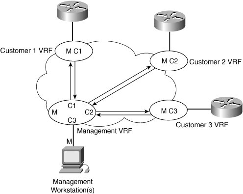
CE Management AccessThe need to access CEs depends on whether the service being offered is managed or unmanaged. Both these scenarios are discussed. Unmanaged CE RoutersIf the CEs are unmanaged, the service provider can use IP version 4 (IPv4) connectivity for all management traffic. Figure 8-8 shows a basic topology with unmanaged CEs. The network management subnet has a direct link to the service provider MPLS core network. Figure 8-8. Network Management of Unmanaged CEs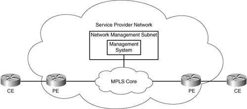 Managed CE RoutersIn managed or hybrid (partially managed) scenarios, connectivity to the CEs from the service provider network is required. This is usually provided in the form of a network management subnet. However, as soon as a CE is in a VPN, it is no longer accessible by means of conventional IPv4 routing. To enable IP connectivity between the service provider network management systems and enterprise-connected CE routers, you must configure a VRF instance on every PE router port connected to an enterprise location to import service provider management system routes. These routes are distributed within the VPN via a dedicated "management VPN" having a unique route target value. All customer-facing PE ports that connect to a service provider-managed CE router must be configured to import this specific route-target value, as shown in Figure 8-9. Figure 8-9. Using a Management VPNCisco Managed MPLS VPN Solution Guide, http://www.cisco.com/univercd/cc/td/doc/product/vpn/solution/manmpls/overview/mmpls_ov.pdf A network management VRF table contains the circuit addresses of all CE routes. The service provider management workstation(s) originate from this VRF. Each customer VRF should contain the address of the service provider management workstation(s) to allow two-way communication between the management workstation and the CE router. When a management VRF is created,
All CE routers are easily identified because they all use a circuit address from the same service provider-managed address space. Example 8-1 shows a sample configuration of a customer VRF for use with a management VRF. This is an excerpt from the output obtained using the show running-config command. Example 8-1. Customer Management VRF Configuration
Example 8-1 shows the use of two additional route targets:
The management VRF is configured at the PE that connects to the service provider management subnet. Example 8-2 is a sample configuration (taken from the show running-config output). Example 8-2. Management VRF Configuration
In Example 8-2, the VRF uses the service provider-specified route distinguisher (RD) and route target (RT) of 1000:1. In addition to the normal import/export route targets for the VRF, two route maps are specified: IN-Management and OUT-Management. The IN-Management route map limits any imported addresses to those of the PE-CE circuit address space. In other words, the address prefix must be a /30 subnet beginning with 8.1.1.0, 9.1.1.0, and so on. This prevents all other routes in the customer VRFs from being imported. Because the management VRF is connected to an interface, which originates many subnets, static routing is used to specify how to reach it. In this example, the management subnet is 190.1.42.0. To guarantee that only the host addresses of management workstations are exported from the management VRF, static routes are used to identify each management address individually. The OUT-Management route map then sets all management host addresses (those that match access list 0) to the extended-community attribute of 1000:10. They are then imported into the customer VRF with a corresponding import map. Network Management Configuration ConsiderationsIf the management host addresses in the preceding configuration are redistributed to a CE through a routing protocol such as Routing Information Protocol version 2 (RIPv2), the CE can readvertise the route back to the PE in a summarized form. This occurs even though split horizon (which does not send routes out an interface on which they were received) is enabled. For example, if the host route 190.1.42.3 255.255.255.255 is advertised to a CE with auto-summary enabled, that route is summarized to a B-class address of 190.1.0.0 255.255.0.0 and is advertised back to the PE. The split-horizon process lets the route pass because it is not the same as the route that was received. There are two ways to avoid re-advertising routes back to the PE router:
Another useful technique is to configure CE devices with a loopback interface, the IP address of which is used as the management address of the CE router. The CE router must be configured to advertise this address with a 32-bit mask to the PE router. The PE router in turn exports only this loopback interface address with a 32-bit mask to the service provider management VPN using a second unique route target value (different from the import value previously mentioned). In this scheme, there should not be any requirement to export the PE-CE interface network address to the management VPN. All other IP prefixes received by the PE router from the CE router are exported to the customer VPN only. No customer IP prefixes other than the CE router loopback address are advertised within the management VPN. Acceptance TestingIt is highly recommended that the enterprise perform some form of formal acceptance testing of new circuits and sites. This typically consists of the following steps:
Tip Use an extended ping to test a range of packet sizes. This will help you discover failures that occur only near the 1500 maximum transmission unit (MTU) limit. Note that this requires the Do Not Fragment (DF) bit to be set in the header, as shown in Example 8-3. Example 8-3. Using Extended Ping to Test a Connection
For QoS, a basic test can be performed using extended ping commands to insert QoS markings and validate that the service provider is handling them correctly by capturing appropriate statistics on the remote devices. Note Because extended ping allows the type of service (ToS) byte to be set, you must be careful to use correct values when mapping from Differentiated Services Code Point (DSCP). For example, if you intend to simulate voice, it has a DSCP value of 101110. However, the ToS byte needs to be set to 10111000 (decimal 184), not 5 as is sometimes assumed. Tip For best results, originate the tests from behind the CE devices to test firewall capability. It is also useful to perform these tests after the VPN goes live. MonitoringEven though the service provider may monitor its network for SLA purposes, it is highly recommended that the enterprise perform its own monitoring. There are several reasons for this:
There are basically two relevant forms of monitoring: availability and performance or service degradation. For availability, this may be a measurement at the host or site level or both. Because of network glitches and transient conditions, the monitoring solution should contain an element of "damping." This helps keep false alarms from being raised. An example might be a solution that pings hosts every 10 seconds but uses a sample period of several minutes to derive an availability measurement. The second form of monitoring is for performance or service degradation. A relatively simple metric can be obtained using the same scheme as for availability, but taking into account round-trip times. A more sophisticated scheme might involve dedicated probes. For example, the Cisco IOS IP SLA provides a mechanism to monitor performance for different classes and types of traffic over the same connection. This technology could be used to monitor the response time between a Cisco device and an HTTP server to retrieve a web page. OptimizationThe main objective of optimization is to increase application performance (because this can be directly correlated with productivity). An important part of optimization is calculating required bandwidth. Recent technologies have tried to simplify this whole process by providing bandwidth recommendations based on individual traffic classes. An example is bandwidth estimation within Cisco IOS. This technology produces a Corvil Bandwidth value, which is the minimum amount of bandwidth required to meet a specific QoS target. This technology is most applicable at the WAN interface point between enterprise and service provider networks. Note This feature is currently restricted to IOS 12.3(14)T and requires a special license. More information can be found at http://www.cisco.com/en/US/tech/tk543/tk759/tech_brief0900aecd8024d5ff.html and http://www.cisco.com/univercd/cc/td/doc/product/software/ios123/123newft/123t/123t_14/gtcbandw.htm Of course, increasing bandwidth may not always be an option. Other techniques include caching, compression, and increasing transmission/application speed. All of these require dedicated management system support, but the return on investment (ROI) would make such an investment worthwhile. |
EAN: 2147483647
Pages: 136