Basic Security Techniques
| This section examines five network techniques or capabilities that can be considered basic or required implementations for entry-level security for systems connected to today's Internet:
Remote-Triggered Black-Hole FilteringThe idea behind the remote-triggered black-hole filtering technique is to use a routing protocol to quickly disseminate a route to Null0, which essentially drops the traffic that is part of an attack. Here's a scenario: Imagine that an enterprise has a web server under attack. The attack's address is specific to the web server itself. Therefore, no matter what technique an attacker is using to conceal the attack's real source (or, indeed, using multiple compromised hosts to launch an attack from many locations), the destination is known and constant. The objective is to quickly disseminate to the edge of the network something that will instruct the edge routers to drop the attack packets. The result is that both attack and valid packets to the attack destination are dropped, so service is not restored to the attack host at this stage. However, the rest of the resources on the attacked network are available, such as web access, other servers, e-mail, and so on. This is so while the attack is going on, service may be denied to the entire network, either due to router resource exhaustion (if the attack consists of small packets) or bandwidth exhaustion (if the attack consists of large packets). However, without the attack packets, everything except the object of the attack can have service restored, and no collateral damage occurs. Note The technique just discussed uses a routing protocol as a security tool. Let's digress and examine why this approach is superior to ACLs. It is tempting to rely on implementing an ACL scheme to block attack packets from entering a network while the attack is under way. However, consider the challenges of that approach in the case just defined. With a host under attack, the standard ACLs have failed. The attack is getting through. So to update the ACLs, the attack has to be identified and a new ACL created and pushed to all edge devices. This is a significant operational challenge. As the number of routers that need this new protection grows, so does the challenge of updating their ACL configuration. So, if you were to look at ACLs as the solution to dropping these attack packets, you would have to be able to update the ACL configuration of 50, 100, or more routers within a minute or so, not have this make any impact on forwarding performance, and be able to use the feature in a consistent manner across all products. Providing ACL features to do this on hardware- and software-based forwarding systems simultaneously is not trivial. However, all platforms support BGP. They drop packets to null0, and the entire network is updated as quickly as BGP (or another routing protocol) updates the edge devices. So how does this get done? Here's how:
The first question that may arise is why not send an update directly to null0 for the attacked host to all edge routers? Well, the answer is that when advertising route updates, BGP needs to send an IP address as the next hop. It cannot send an interface as a next hop, so you must introduce this step. How is this set up? First, the static route to null0 must be defined on each router that will be asked to drop packets destined for the attacked host. The IP address used in this static route must be one that you never expect to have to transit traffic for, or use within your network. A recommended address space is the one set aside for documentation, 192.0.2.0/24, so this would manifest itself as a static route on each router as follows: ip route 192.0.2.1 255.255.255.255 null0 255This sets the next hop for the 192.0.2.1/32 address to the null0 interface. Next, the trigger router has to be set up. It is most commonly set up as a route reflector client. The configuration on the router must achieve the following objectives:
So, the preattack configuration on the trigger router includes the following: Router BGP 65534 ! redistribute static route-map black-hole ! route-map black-hole permit 10 match tag 99 set ip next-hop 192.0.2.1 ! route-map black-hole permit 20 Here, the router is told to redistribute static routes if they have a tag of 99 and then to set the next hop to 192.0.2.1 for them. The entire process is triggered when you now enter a single static route, tagged to 99 on this router (in the following example, you want to black-hole traffic for 177.77.7.1): ip route 177.77.7.1 255.255.255.255 null0 tag 99The trigger black-holes traffic to 177.77.7.1 and, via BGP updates to the rest of the routers, tells them to do the same. After the trigger router has picked up the tagged route, an update for route 177.77.7.1 is sent with a next hop of 192.0.2.1. As soon as each edge router receives that, the recursive process of determining which interface to use for 177.77.7.1 begins, resulting in all traffic for 177.77.7.1 being sent to null0. What has been done so far is a very quick way to eliminate that specific attack. The process of tracking this to the source can now begin, safe in the knowledge that collateral damage has been eliminated and all other services are up and running on the network that was under attack. After the source of the attack has been identified and removed, full service to the web server that was attacked can be provided. There is one issue to consider before we move on to discuss how you can quickly eliminate attack traffic from specific sources (whether spoofed or not). Routing to null0 is fine for hardware-based forwarding devices (it merely takes the clearing of a hardware register), but this can be an issue for software-based forwarding. The reason for this is that the routing software is optimized to forward packets, not drop them. So for forwarding-based devices at the edge, it may be preferable to set the next-hop interface to a physical interface that has no other peers or hosts connected to it. This allows the router to continue forwarding packets optimally and sending attack packets to a destination that leads nowhere. Loose uRPF for Source-Based FilteringAfter the attack packets to the specific host under attack have been stopped, you have time to research the attack and determine its source. Using the Arbor system delivers that information in a timely fashion. As soon as the attack's source is identified, you need to drop packets coming from that source so that you can then allow packets destined for the attacked host to start flowing, safe in the knowledge that the attack packets have been stopped. To do this, you need to check source addresses at the network's ingress. That could be accomplished with ACLs with a lot of manual intervention during an attack. However, by using a feature called unicast Reverse Path Forwarding (uRPF) in conjunction with the remote-triggered black-hole filter technique described in the preceding section, it is possible to use the routing protocol to more quickly and intelligently block these unwanted packets.
Although it is not essential to understand this technique to use it, loose uRPF checks to see if a route back to the source address exists in the forwarding information base (FIB) of the router performing uRPF. If a route does not exist, the packet is dropped. Likewise, if the packet is being forwarded to a next hop with a value of null 0, it is also dropped. This allows you to use exactly the same configuration that was used for destination-based black-hole filtering. However, the trigger route set up on the trigger router no longer is the destination you want to black-hole traffic for, but the sources you want to black-hole traffic from. The only extra piece of configuration needed to enable this technique is to set up loose-mode uRPF on each interface on the edge routers. This can be achieved by using the following interface-level command: ip verify unicast source reachable-via anyStrict uRPF and Source Address ValidationStrict uRPF is a way to implement part of the filtering requirements defined in RFC 2827, Network Ingress Filtering: Defeating Denial of Service Attacks Which Employ IP Source Address Spoofing. This is called BCP0038. It defines ingress filtering to defeat DoS attacks using spoofed addresses. RFC 2827 recommends that an Internet service provider's (ISP's) customer should not send any packets to the Internet with a source address other than the address allocated to him or her by the ISP. This is a good goal, but the question is how to scale its implementation. This becomes operationally feasible if it can be implemented without the need for a unique ACL for each interface and if the filter can be dynamically updated to accommodate changes in address allocation. uRPF can meet these goals with a single configuration for each interface. uRPF uses the CEF table for drop decisions, which is updated by routing protocols. uRPF works for all single-homed connections. Extra configuration may be necessary for some dual-homed configurations. This feature is useful not only for ISPs to be assured that no customers are spoofing source addresses. It is also useful for enterprises to implement on their edge routers. Basically, no packets from the Internet should arrive with a source address in the range that's allocated to the enterprise. The typical implementation inserts the ip verify unicast reverse-path command under the interface configuration of the serial interface connecting the enterprise router to the provider. Figure 7-9 shows the two operations of uRPF. Figure 7-9. uRPF Strict and Loose Modes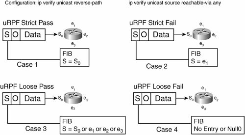 In Figure 7-9, Case 1 is where we implement strict uRPF and the packet entering the router on serial 0 passes the check. The pass is based on the source address of the packet matching an entry in the FIB for the interface the packet was received on. Case 2 is a situation in which the packet gets dropped, because the packet coming in to serial 0 has a source address that can be reached via Ethernet 1. This packet would be permitted in the uRPF check of Case 3, where the packet's source address can be any address that the router knows. Case 4 shows what causes uRPF loose to drop the packet. Either there is no FIB entry for the source, or the source address has a next hop of null0 (which is what we use to trigger black-holing). With strict uRPF enabled, attacks like the smurf and its cousin, fraggle (which uses User Datagram Protocol [UDP] echo packets in the same fashion as ICMP echo packets), are not possible. The smurf attack, which is named after its exploit program, occurs when an attacker sends a large amount of ICMP echo (ping) traffic to an IP broadcast address. By sending traffic to the broadcast address, each host on that network (or subnet, more specifically) responds to the ping, amplifying what was a single packet sent into however many hosts there are on the subnet attacked (see Figure 7-10). There are two variants of this:
Figure 7-10. Smurf Attack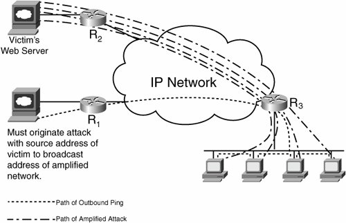 Clearly, an attacker cannot use this form of attack if strict uRPF is implemented on the ingress to the IP network shown in Figure 7-10. Whether the attacker spoofs with bogon source addresses or the source address of an intended victim, neither passes the uRPF check. Sinkholes and Anycast SinkholesThe concept of a sinkhole is simple: If a destination is under attack, divert the attack traffic to a safe place on the network, where the attack traffic no longer causes collateral damage and can be further analyzed, classified, and mitigated. Sinkholes are an essential piece of the security infrastructure. More uses for them are being created within the security community all the time. In fact, sinkholes typically are gainfully employed even when there is no attack alert. It is common practice to have a sinkhole router or UNIX machine advertise pieces of bogon addresses and dark IP space (which are IP addresses that were legitimately allocated but that are not in use by the owner) to see if anyone is probing to find an attack. In fact, sinkholes can get more sophisticated than just advertising bogon or dark IP addresses to lure attackers. They can also be set up with web servers to make attackers think that they have found something to exploit, while the source of the attack can be traced. Sinkholes can be set up in one of two ways:
Sinkholes should be deployed in multiple layers of the IP network, in the service provider, in the demilitarized zone (DMZ) network, and within the enterprise. In fact, coupling a sinkhole with an analysis tool such as the Arbor Peak flow system provides an excellent tool for identifying, classifying, and mitigating many forms of DoS attack. One example is within the Cisco network, where this setup is common. During an attack, the sinkhole attracts traffic, and the Arbor system identifies it and creates a recommended ACL to stop the attack. This can then be brought in to something like CiscoWorks or a Perl script to distribute to the entire network. In some of these cases, the Arbor system picks up the scans that some worms deploy to proliferate. (More on worm behavior and mitigation appears in the section "Worm Mitigation.") For example, in the case of the Sapphire/Slammer worm, Arbor would have picked up the new activity on UDP port 1434 and created an ACL definition to block that traffic far quicker than any mechanism using human intervention. Note You can find more details on the Sapphire/Slammer worm at http://www.caida.org under the papers link. Backscatter TracebackBackscatter traceback is a quicker method of the hop-by-hop tracing technique. It uses several of the previously mentioned techniques in combination, so it had to be saved for last. The concept you want to realize is getting the edge routers to tell you which ingress interface the attack using spoofed source addresses is coming from. As you know from setting up destination-based black-hole filtering, if a host is under attack from a stream of packets with spoofed source addresses, you can push a route to null0 to the edge for the attacked host address. This causes the edge routers to drop the attack packets. From RFC 1812, you know that the router must generate a destination-unreachable ICMP message in response to dropping a packet being routed to null0. With the black-hole filtering discussed so far, there is no route back to the source originating this ICMP message, so the destination-unreachable messages go nowhere. However, what if you gave the router a place to send those unreachables and logged them for viewing? The result is that you would instantly be able to identify the edge router receiving the spoofed source address attack and the interface that router is receiving them on, because both would be identified in the unreachable message sent to the logging device. So, the components are implemented in this fashion. The sinkhole advertises large amounts of bogon and dark IP space, with the expectation that if an attack comes in, it uses random spoofed addresses, and some match the address space advertised by the sinkhole. An example of this is 96.0.0.0/6. The edge routers are set up with the usual static route of 192.0.2.1 to null0. The trigger router is ready to redistribute the route of the attacked host (picking 172.16.18.1 for this example) to have a next hop of 192.0.2.1. The trigger router that advertises the 96.0.0.0 space (of course, care must be taken not to advertise this outside your network by egress filtering) needs to be set up with an ACL to generate log messages for the ICMP unreachables it receives. The ACL is implemented inbound on the interface you expect the ICMP unreachables to reach the sinkhole router on. It would look something like this: access-list 101 permit icmp any any unreachables log access-list 101 permit ip any any Figure 7-11 shows the complete process. Figure 7-11. ICMP Backscatter Traceback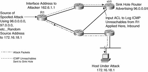 So, assuming that an attack is in progress on 172.16.18.1 and that one of the attack packets uses a spoofed source address of 96.0.0.1, what will be seen in the log of the sinkhole router? The first thing to do is issue this command on the sinkhole router: router2#show access-list 101 Extended IP access list 101 permit icmp any any unreachable log (20000 matches) permit ip any anyThis tells you that the sinkhole router is seeing lots of unreachables inbound on the interface the ACL was applied to. The next thing is to look at the log on the sinkhole router to get information on where all these unreachables are coming from. The output of the log on the sinkhole router looks something like this: 01:03:04: %SEC-6-IPACCESSLOGDP: list 101 permitted icmp 162.6.1.1 -> 96.0.0.1 (3/1), 99 packets Now you know where this is coming from. The router with customer-facing interface 162.6.1.1 is sourcing ICMP unreachables when it is trying to tell source 96.0.0.1 that it can no longer reach 172.16.18.1 (because 172.16.18.1, the target of the attack, has now been black-holed). The code 3/1 tells you that these are unreachable messages, because ICMP unreachable code 3 means destination unreachable and type 1 refers to a host address. However, there are a few issues to consider. First, you must check that your equivalent to R1 in Figure 7-11 does in fact generate ICMP unreachables under these conditions. Also, generating large numbers of ICMP unreachables can cause CPU overload, depending on the hardware. The workaround for this is to implement ICMP rate limiting: router(config)#ip icmp rate-limit unreachable nn is the number of milliseconds between two consecutive ICMP unreachable packets. The default value is 500, which means that one ICMP unreachable packet is sent every 500 ms. Note Full details on this issue are available at http://www.cisco.com/en/US/products/products_security_advisory09186a0080094250.shtml. These techniques are applied with the enterprise network. They take on more significance when MPLS VPNs add richer connectivity to the WAN infrastructure. MPLS VPNs add any-to-any connectivity within the WAN to support applications, such as VoIP. In many cases, they enable quicker extranet connectivity. These business benefits are significant; however, they do come at a pricethe additional effort needed to trace attacks and provide security in the new environment. Cisco GuardCisco Guard is a relatively new product that automates some of the actions described here. It now forms a key part of the DDoS mitigation plan of many enterprises with large IP networks, as well as service providers. Cisco Guard and Cisco Detector are two pieces of the anomaly detection and mitigation solution that are marketed by Cisco. Cisco Detector performs attack detection and identification. The Detector communicates with the Guard, which diverts specific traffic for on-demand protection. Placement of these devices is shown in Figures 7-12 and 7-13. Figure 7-12. Dynamic Diversion Architecture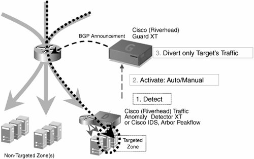 Figure 7-13. Dynamic Diversion Architecture, Continued Figure 7-12 shows what happens when an attack occurs: attack traffic to the targeted zone passes freely. However, when this new attack traffic flows, it is detected by Cisco Detector, which notifies Cisco Guard automatically. Cisco Guard then uses BGP or another routing protocol to redirect attack traffic, as shown in Figure 7-13. The primary benefit here is that the Guard and Detector can work in unison not only to detect the anomaly but also to implement a mitigation schema, all without human intervention. After the traffic is diverted, you can further inspect it to detect its source and remove it from the network. As a matter of design, the Detector needs to be as close as possible to potential targets of attack, and the Guard has to be as far upstream as possible. In the case of an enterprise connecting to a provider, the enterprise cannot install the Guard any further upstream than the PE-to-CE link unless specific provisions are negotiated with the provider. In that situation, the Guard can protect downstream resources from the attack but does not stop the attack from getting as far as the provider PE router. In that case, communication with the provider is necessary to stop the attack traffic. |
EAN: 2147483647
Pages: 136