Case Study: Implementing Multicast over MPLS for Acme
| Acme and the service provider agreed that PE router interfaces would always be enabled for multicast, irrelevant of bandwidth. Acme would decide on the CE router WAN interface whether to enable multicast. The configuration on the CE router to enable MVPN requires you to enable multicast on the CE router first. Then, to enable MVPN on the CE WAN interface connecting to the PE, you use the standard PIM sparse-dense mode command. You can use this command to enable multicast on a traditional WAN interface. Multicast AddressingA multicast group address is a destination IP address within an IP packet. The packet has no single destination within a network. An IP packet with a multicast group address has the destination of an arbitrary group of IP hosts that have joined the group and that want to receive the traffic sent to the group. The multicast group address range 224.0.0.0/8 (assigned by IANA) is broken into a number of smaller ranges for specific purposes, as shown in Table 6-3.
IANA has reserved the range of 239.0.0.0/8 as administratively scoped addresses for use in private multicast domains, as shown in Table 6-3. This address range is similar to RFC 1918, and IANA does not assign this to any other group or protocol. Table 6-4 shows the present multicast admin scope standard that allocates specific ranges of group addresses within 239.0.0.0/8 to be used for certain bit rate streams.
Multicast Address ManagementThe key to allocating multicast group addresses is working with the teams sourcing multicast traffic and fully understanding their requirements. One of the main reasons it's important to work with teams using IP multicast is because no mechanisms exist today on the network to notify or alert operational network engineers or the team sourcing traffic that the wrong group addresses are being used or the wrong rate is being transmitted on the allocated addresses. For example, suppose an IPTV server starts sourcing 1 Mbps of IP multicast content using a group address from the low bit rate admin scope, and users at the remote office ask to receive this content. The 1 Mbps streams attempt to flow across the T1 or E1 (1.5 Mbps or 2 Mbps) WAN link connecting the remote site. The result of such an action would affect other multicast traffic unnecessarily by using more bandwidth than required, thus dropping IP multicast packets. Chances are, users will think that this is poor service. Therefore, it's important for network engineers to work closely with teams sourcing IP multicast to explain these potential issues and allocate IP multicast group addresses appropriately per the requirements. The IP multicast group addresses allocated must be reserved in the appropriate address management tool employed. Predeployment ConsiderationsThe primary IP multicast application using the MVPN service is IPTV. It generates 1480-byte packets because the default setting in the server's iptv.ini file is 1452. The IPTV server produces 1452-byte Routing Table Protocol (RTP) packets, which results in multicast packets of 1504 bytes from the following calculation: 1452 + 8 UDP + 20 IP + 24 GRE = 1504. The PE router needs to fragment the 1504-byte packets if a 1500-byte interface for PE-P and/or P-P links is used in the network. If the network has all WAN interfaces with a 4 Kbps maximum transmission unit (MTU), it's not an issue. Depending on the hardware and topology used, a service provider might be able to increase the MTU of all PE-P and/or P-P interfaces to be slightly more than 1500 bytes to account for the GRE overhead. Caution should be taken when changing the MTU, because it is a difficult-to-administer workaround. As a result of fragmentation on the PE, the route processor must handle each of these packets. The Selective Packet Discard (SPD) punt limit is set to the default of 1 k pps. Thus, it does not take long before this threshold is exceeded and the PE router starts to discard packets to protect the route processor. The workaround for this problem is to lower the MTU from 1452 bytes to 1280 bytes on all Acme internal IPTV servers globally. The server administrator can change this figure in the IPTV server's iptv.ini file. 1280 bytes was chosen because it is the lowest supportable figure for IPv6. This solution is much more preferable than having the service provider manipulate the MTU setting it has set for the enterprise. MVPN Configuration Needs on the CEThe first step of enabling multicast on a Layer 3 device is to enable multicast routing, which is not enabled by default. Enter the following command to enable multicast routing on a router: router(config)#ip multicast-routingFor high-end routers, such as 75xx or 12xxx, that support distributed forwarding of multicast traffic, the following command should be used to enable multicast routing: router(config)#ip multicast-routing distributedEnabling the SSM range on a router defines the group address range that will be used to deliver SSM content. This is especially important on edge routers, known as the "source server's first-hop routers," which connect to the VLAN/subnet hosting the source server, and the "receiver's first-hop routers," connecting directly to the user's VLAN/subnet. Enabling SSM on the "source server's first-hop routers" prevents the router from forwarding the multicast traffic encapsulated in a unicast register to the RP. Enabling the SSM range on the "receiver's first-hop routers" prevents (*,G) joins from being sent by the DR toward the RP to build a shared tree when a new receiver wants to join a specific SSM group. The DR now realizes that this is an SSM group address and sends an (S,G) toward the source IP address: router(config)#ip pim ssm range multicast_ssm_range router(config)#ip access-list standard multicast_ssm_range router(config-std)#REMARK ACL to define SSM admin range router(config-std)#REMARK 232.0.0.0/8 IANA allocated SSM range router(config-std)#permit 232.0.0.0 0.255.255.255 router(config-std)#REMARK 239.232.0.0/16 Internal SSM range router(config-std)#permit 239.232.0.0 0.0.255.255 Note The preceding SSM configuration should be applied to all multicast-enabled routers in the global transport network. Applying the commands to all multicast-enabled routers in the network has no detrimental effect, but instead keeps the configuration consistent. This approach also simplifies the multicast configuration being deployed rather than having only SSM applied where it's truly required, which is on the "receiver's first hop" routers. The main requirement is to ensure that PIM sparse-dense mode is configured on the CE WAN interface connecting to the PE. PIM sparse-dense mode must also be configured on the WAN interface of the PE connecting toward the CE. While the PE is under the control of the SP, it serves as a useful troubleshooting reminder that this must be enabled on the local CE-PE interfaces to work properly. The commands required are as follows: CE router: router(config-if)#ip pim sparse-dense-modePE router: router(config-if)#ip pim sparse-dense-modeA carrier deploying an enterprise-wide MPLS VPN cloud should be instructed to enable ip pim sparse-dense-mode on all WAN interfaces of the PE connecting to the customer. This ensures that the control exists on the Acme side to determine if PIM should be enabled. This is especially important in regions that have WAN links less than 256 kbps. Boundary ACLWhen multicast is enabled in an enterprise network, the environment naturally consists of various WAN circuits of differing speeds. At Acme, content is primarily produced from central locations, and these source servers offer various quality multicast streams. The better-quality streams have a higher bit rate. Therefore, they can be delivered only over WAN circuits with sufficient bandwidth to handle that higher bit rate. A method is required to control the flow of multicast streams in this type of environment. You need to ensure that remote sites with slow WAN circuits can view only low-bit-rate streams. They must not be able to view a high-bit-rate stream that could saturate the WAN circuit and affect other traffic traversing the link. One method to control the flow of multicast traffic based on destination address and the feature is multicast boundaries. In Figure 6-7, the routers block medium- and high-bit-rate streams and allow the low-bit-rate stream to pass over the WAN circuit. Figure 6-7. Multicast Boundaries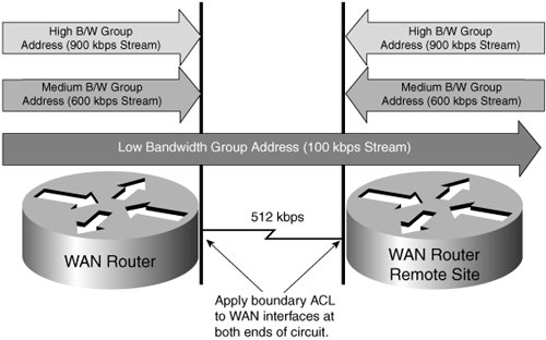 Note Using boundaries to protect resources from high-bandwidth multicast is only an administrative boundary. If an IP multicast source server is connected to the network and it starts streaming 1 Mbps of IP multicast traffic using a group address that should be used for low bit rate, this could result in problems. Thus, it is very important that teams sourcing IP multicast traffic be educated on the importance of good IP multicast group address management. Boundary ACLs must be configured on the WAN interfaces of the CE only. Each access list allows only a certain range of multicast destination addresses to pass while blocking other bit-rate streams. When an access list is applied to a router interface that allows only certain bit-rate streams to pass, this is known as defining a multicast boundary. At lower-speed sites, the application of the boundary ACLS should be applied on the local site's ingress interfaces, where distribution switches are downstream from the WAN edge. At such sites, processing of boundary ACLs could easily be employed on the distribution to offload processing of the boundary ACLs, allowing the ACLs to be processed in hardware. The standard access list defining the multicast boundary should be applied to WAN circuits falling into specific bandwidth ranges. The access list allows only specific address groups to pass that are the destination addresses of multicast streams with a specific bit rate. Which standard access list should be applied to what bandwidth interface can be determined from Table 6-5.
Positioning of Multicast BoundariesMulticast boundaries should be deployed in the network at the CE aggregation routers and remote-site CE routers. The following sections explain the content of the standard access lists, where to locate them, and how to configure them on a router. Using named ACLs benefits network engineers because it removes an element of uncertainty and confusion by documenting the bandwidth range covered by the ACL in the ACL title itself. Leading practice should be used in the form of the REMARK statement in the ACL to further enhance documentation. The global multicast range is from 224.0.0.0 to 238.255.255.255, as highlighted in Table 6-3. Note that this boundary ACL blocks only 224.2.x.x because IPTV uses that range by default. To avoid any issues with IPTV servers being connected to the network at remote sites and using default addresses, this range is blocked to prevent the content from potentially affecting the WAN link. Note Care should be used to ensure that the blocking of global ranges does not potentially block Internet-based content or other applications. You are urged to confirm the use of the ranges to ensure that there is no impact on applications that are unintentionally using the global multicast range. Configuration to Apply a Boundary Access ListTo apply a multicast boundary to a router interface, use the following command, and associate it with one of the standard named access lists. It is also a best practice to apply multicast boundaries to the router interfaces at both ends of a WAN circuit. This keeps sources at the remote site from causing issues. router(config-if)#ip multicast boundary acl-name Two standard access lists have been developed for multicast boundaries: multicast_boundary_lowbw and multicast_boundary_medbw. The ACL multicast_boundary_lowbw allows low-bandwidth streams, as shown in Example 6-1. Example 6-1. multicast_boundary_lowbw
The ACL multicast_boundary_medbw allows bandwidth streams of less than 700 kbps, shown in Example 6-2. Example 6-2. multicast_boundary_medbw
Rate LimitingRate limiting should be applied to protect the bandwidth of a WAN circuit connecting a remote office to the corporate network. This is critical for lower-bandwidth circuits or when sending higher-bit-rate streams over midrange bandwidth, especially if multiple multicast streams are being transmitted over the WAN circuit. The carrier may also implement the "mroute rate limit" feature to restrict the number of mroutes Acme, Inc. can advertise into the cloud. This is done to prevent the CE from advertising too many mroutes to the PE that would consume too much of the PE router's memory. Table 6-6 is a simple guideline that can be used to help you determine if rate limiting should be applied. If rate limiting is to be applied, it's important to determine what percentage of available bandwidth should be made available to multicast. This list covers most of the circuit bandwidths currently used in Acme's internal network. This does not mean that the proposed rate limiting must be applied to higher-bandwidth circuits if the operational engineers deem it unnecessary. When applied, it rate-limits the multicast traffic. Table 6-6 shows the circuit bandwidth application of rate limits.
The best approach to calculate the rate-limit figure that should be applied in your configuration is to first determine the bandwidth of the WAN circuit in question. Take the bandwidth figure from the first column of Table 6-6, and then determine the recommended percentage in the next column. If you feel the resulting figure is too high or too low due to facts such as current utilization figures or demand at the site, alter the percentage as you feel necessary. However, remember that this command must be applied in a manner to protect your WAN circuit bandwidth from being overrun by multicast traffic. Take the percentage figure and calculate the kilobits per second (kbps) multicast rate limit from the circuit bandwidth that you want to apply. The best practice is to apply rate limiting to both interfaces at the A and B ends of a WAN circuit. This approach protects the circuit bandwidth if the remote site is hosting a multicast source. When working with smaller-bandwidth circuits, the minimum rate-limit figure should be 160 kbps to allow for a media bandwidth of one stream @ 100 kbps video + 16 kbps audio + burst. Note The example used would only apply to a link of 256 kbps. If you were to apply 50 percent to a circuit of this size (which results in 128 kbps available for multicast), you would fall below the minimum required figure of 160 kbps. Remember to use the figure of 160 kbps if 50 percent of the link bandwidth is less than 160 kbps. Rate-Limiting ConfigurationAfter you have calculated the kbps rate-limit figure that you want to apply, use the following configuration command to apply that to the router interface: router(config-if)#ip multicast rate-limit out max-mcast-bw-in-kbpsMVPN Deployment PlanThe migration plan to MVPN requires several stages to ensure that the IPTV service can be supported through each phase of the core transition. The following stages, including precutover testing, postproduction testing, and configuration preparation, are carried out to complete thorough testing: Precutover Testing: Nonproduction
Postproduction Testing
Configuration Preparation
Preproduction User Test SequenceThe preceding test procedure was carried out during the preproduction checks with users in London, Amsterdam, and Brussels. This is to see if any packet duplication occurs when multiple joins are made. Figure 6-8 depicts the test setup. As you can see, users are based in Brussels and Amsterdam. The rendezvous point is configured to point to Amsterdam. It also provides a view of the deployment scenario. Figure 6-8. Test Setup for Multicast over MPLS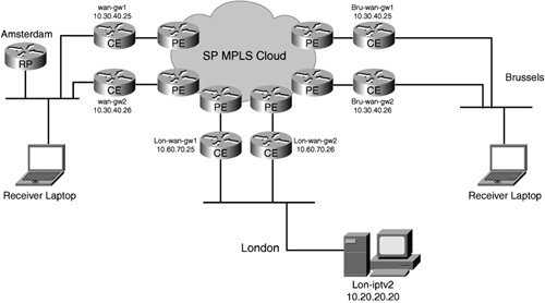 The preproduction test environment that is used is the closest to capturing the post-production setup before the cutover. This helps test IPMC behavior and the end-user scenarios. The sequence of testing aims to thoroughly verify that no looping issues occur when join requests are made by users at each of the sites. First, verify that few or no active streams in the network exist before cut testing.
It is important to verify that users are not having any difficulty viewing streams in different locations. The following checks were made:
The following testing was carried out to see if any issues were occurring:
The following test criteria were used to receive feedback from users on the quality of the test streams: User feedback survey IPTV multicast test plan and checklist
Test 100 kbps test streamlon-iptv2 Content Manager
Test 900 kbps U.S. test streamsj-cm Content Manager
Test 500 kbps U.S. test streamsanjose-cm Content Manager
Test 100 kbps U.S. test streamsj-cm Content Manager
Internet: TV-broadcast stream | ||||||||||||||||||||||||||||||||||||||||||||||||||||||||||||||||||||||||||||||||||||||||||||||||||||||||||||||||||||||||||||||||||||||
EAN: 2147483647
Pages: 136