Defining the Object Model
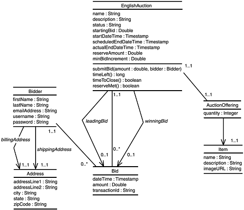
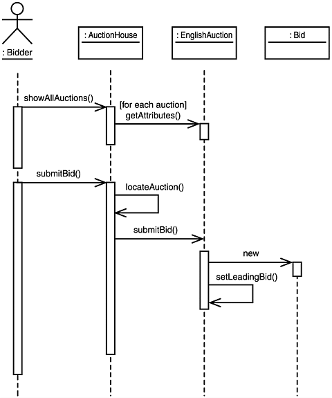
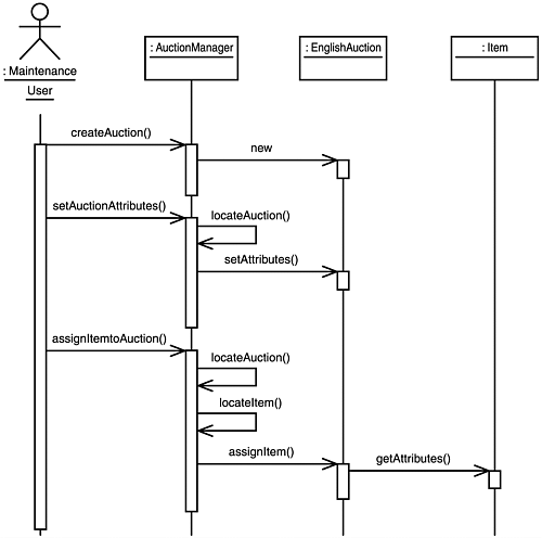
| The code for the auction site's application tier will evolve as new concepts are introduced, but an initial object model can still be defined as a foundation. A good bit of analysis and design work is needed to go from use cases to an object model, but most of that detail will be skipped for now so that the interesting design decisions can be looked at relative to EJB in later chapters. Even though it's too early to talk about where EJB fits into the design, some basic architectural goals can still be covered to start firming up what needs to be built. First of all, the subject of this book makes it a given that the auction site will be built on a multi-tiered J2EE architecture. In a nutshell , this means that all HTML generation for the user interface will be performed using servlets and JSPs in a Web tier that is decoupled from the business logic. All business logic will be contained in EJBs running within an application tier that is responsible for all communication to the enterprise information systems tier (a single relational database in this case). These decisions alone short-circuit a lot of potential design issues that would normally have to be considered . To stay focused on EJB, the detail in the remainder of the chapter will focus on defining a set of initial class and sequence diagrams for the application tier. Identify the Business ObjectsIn addition to using a multi-tiered architecture, the auction site should also reflect a layered architecture. This is especially true in the application tier where both business objects and application logic are found. Business objects represent the key concepts of a problem domain and are typically the persistent objects associated with an application. These objects need to encapsulate the details of the entities they represent, but they should be isolated from the application logic that knows how to use to them collectively to perform application-specific tasks . For example, the items offered for auction by the site might be represented by an Item business object that holds the attributes that define an item and the methods that manipulate them. However, an item can be used in applications other than an auction, so the Item business object shouldn't hold any auction-specific processing. The code that knows how to use an item in an auction should instead be captured in an application controller layer. Maintaining this type of separation makes it easier to reuse business objects across applications. This section comes up with an initial list of business objects needed by the auction site, and the following one looks at a set of application controllers. You'll see in later chapters how the EJBs known as entity beans play a role in business object implementation and those known as session beans do the same for application controllers. In the case of an auction site, a designer would quickly conclude that entities such as the individual auctions, the items available for auction, the participating bidders, and the bids submitted are the primary business objects to be represented in the system. Again, detailing a design process is outside the intent of this chapter, so we'll cover only what you need to get to the results needed to build the example. Many designs are possible, so the one presented here is simply one that was selected to meet the requirements laid out and make for an interesting example. All that's needed at this point is a basic understanding of the classes involved and how they're associated. Figure 2.3 illustrates this using a class diagram. Figure 2.3. Business objects represent the persistent entities needed by the auction site. A class diagram identifies a set of classes in a system and the relationships among them. These relationships include both inheritance relationships and associations between classes. Using UML, a class is represented by a box that contains the name of the class and a list of its attributes and methods. As an example, Figure 2.3 shows an auction business object represented as an EnglishAuction class. This class has several attributes that include a name for the auction and a startingBid . For this particular example, the methods listed in the diagram are limited to the true business methods; so simple get / set methods for the fields aren't shown even though they would likely be needed. The methods that are included identify the business functionality required from the class. For example, an EnglishAuction must be able to accept a bid through a submitBid method that expects an amount and a reference to a Bidder as parameters. Figure 2.3 shows the associations between the business object classes as well. An association is shown in UML using a line drawn between two classes that indicates the cardinality of the association as being one-to-one, one-to-many, or many-to-many. The numbers placed adjacent to this line specify the cardinality using either a single value or a range of values for each side of the association. An asterisk can be used to indicate some number greater than or equal to zero (or the lower bound if the asterisk is used as an upper bound in a range). For example, the association between Bidder and Bid is identified using 1..1 and 0..* . These values mean that a given bid belongs to one and only one auction ( 1..1 ) and a bidder can submit any number of bids ( 0..* ). This is a typical one-to-many association. Two classes are not limited to having a single association between them. As shown in Figure 2.3, three associations exist between EnglishAuction and Bid . These associations represent all the bids submitted for an auction (one-to-many), an auction's leading bid (one-to-one), and an auction's winning bid (one-to-one). The leading and winning bid associations are shown using a slightly different notation that includes an arrow on one end of the line. This notation indicates navigability of an association. In this example, an auction knows its leading and winning bids (that is, it can navigate to them), but a bid does not know if it is the leading or winning bid for an auction. When the arrows are omitted, the association is navigable by either class. Identify the Application ControllersDefining the business objects is a big step toward reaching the goal of this chapter, but the application controllers that interact with these objects also need to be identified. The controller classes are ultimately responsible for implementing the use cases. There are different ways to allocate controller functionality to specific classes, but the approach taken here is to develop a set of classes that represent the real-world individuals or organizations that do the same functions. Specifically, the auction site will be built using controller classes such as AuctionHouse and AuctionManager . AuctionHouse represents the functionality presented to a bidder for obtaining information about the auctions defined by the system and submitting bids. AuctionManager covers the specific functions within an auction house needed to administer auctions. This separation provides the functionality needed by a maintenance user. This type of mapping to controller classes helps a developer intuitively understand where responsibilities lie. It's not necessary to break the controllers down into supporting classes at this point, so there's little need to build additional class diagrams here. However, what is useful is to develop a few sequence diagrams to understand how the controllers are expected to interact with the business objects. A sequence diagram depicts interactions between class instances as messages being passed between the objects. The messages in turn correspond to methods that need to be supported by the associated classes. As an example, Figure 2.4 shows a sequence diagram defining the interactions necessary to support a bid submission. Figure 2.4. A sequence diagram illustrates how application controllers interact with business objects. A sequence diagram focuses on how objects interact to perform a requested operation. This type of diagram illustrates how associations between objects are created and used to perform the work required by a use case. These diagrams provide a dynamic view of a system to complement the static view provided by class diagrams. Each box along the top of a sequence diagram represents an object (not a class, but a single instance). Each object is identified by its class name preceded by a colon that might optionally be preceded by an object name. Typically, you include object names only if more than one object of a particular class type participates in the sequence. The order of the objects across the top of the diagram is unimportant; you should, however, select an order that places the objects with the most interaction near each other to reduce clutter in the diagram. The vertical line that extends beneath each object in a sequence diagram is a lifeline . A lifeline begins when an object is created and ends when it is destroyed . If a lifeline begins at the top of the diagram (just beneath an object box), the associated object exists before the task described by the diagram starts. Similarly, if a lifeline extends to the bottom of a diagram, the associated object still exists when the task is completed. The horizontal arrows between lifelines indicate messages being passed to objects as execution control is transferred. The rectangles drawn along the lifelines are known as activations . An activation indicates that the associated object is either performing work at that time or waiting for another object to return control to it after being sent a message. Activation rectangles are often omitted from sequence diagrams that do not include any concurrent processing by the objects involved. In those cases, the transitions of object activity coincide with the message arrow locations. The sequence in Figure 2.4 begins when the Bidder actor requests the option to view the available auctions. This request is represented by a showAllAuctions message sent to an AuctionHouse instance. This AuctionHouse controller satisfies the request by interacting with each instance of EnglishAuction to obtain the attribute values needed to build the auction list. The user bids on an auction by selecting one from the list and sending a submitBid message to the AuctionHouse . The controller passes the request to the desired EnglishAuction . This auction object creates a new Bid based on the bid amount and the bidder's identity and assigns the new Bid to be the current leading bid. Figure 2.5 shows a similar sequence diagram that illustrates how the Maintenance User uses the AuctionManager controller to create a new auction, define its attributes, and assign an item to be auctioned to it. Figure 2.5. Maintenance Users access the AuctionManager controller to create auctions. |
EAN: 2147483647
Pages: 223