TCPIP Addressing
TCP/IP AddressingThis section introduces the structure of the IP address, including the network, subnetwork, and host portions. We explain how a user determines what IP addressing to use and what configuration commands are required to implement the desired address scheme. Address StructureTCP/IP is a collection of communication protocols that define how different computers are addressed on the network, what methods are used to move information from one computer to another, and some services that are available between computers. The router primarily deals with the network layer (IP) and the transport layers (UDP and TCP) in performing its routing and switching functions.
Internet Protocol (IP), the addressing component of TCP/IP, operates at Layer 3 of the OSI model. Each station that wants to communicate with another has a unique IP address, in the same way that each house on a street has an individual address. The IP address is a little more complex than a street address (computers like those 0s and 1s), but after a little examination, it won't seem so mysterious . At Layer 4 of the OSI model for TCP/IP are the two primary transport protocols, User Datagram Protocol (UDP) and TCP. As mentioned previously, the transport protocols are responsible for basic transfer mechanisms, flow control, reliability, and error checking of communications between stations . UDP is considered unreliable because packets sent using this protocol are not acknowledged by the receiving station. It is considered connectionless because a sending station is not required to advise a receiving station of its desire to form a communications channel over which to pass data. In contrast, TCP is considered a connection-oriented protocol because a sending station must advise the receiving station of its desire to form the communications channel. Packets sent via TCP are tagged with sequence numbers , and the sending and receiving stations each acknowledge the receipt of one another's packets. The IP address is a 32-bit binary address written in four groups of 8 bits called octets. The complete address represents the three components of the addressing model of IP ”namely, the network, subnetwork, and host portions of the address. First, let's look at the address numbering itself. A typical IP address written in 32-bit binary might look like the following: 10101100.00010000.00000001.00000001 Each of the 8 bits in an octet can take on the value of 0 or 1. Therefore, the values can range from 00000000 to 11111111 in each octet. You can already see that managing 32-bit addresses in binary can be cumbersome and prone to errors. Recognizing that fact, the developers of TCP/IP decided that the binary should be reserved for computers and that IP addresses should be converted to decimal form (the common way people look at numbers) for easier human interaction. Therefore, an octet in which all bit positions are set to 1 is equivalent to 255 in decimal form: 1 1 1 1 1 1 1 1 = Binary Positions 128 64 32 16 8 4 2 1 = Decimal Equivalent Adding up the decimal equivalent of the binary number, we have the following: 128+64+32+16+8+4+2+1 = 255 Now, let's convert an address example: 1 0 1 0 1 1 0 0. 0 0 0 1 0 0 0 0 . 0 0 0 0 0 0 0 1 . 0 0 0 0 0 0 0 1 128 64 32 16 8 4 2 1.128 64 32 16 8 4 2 1 . 128 64 32 16 8 4 2 1. 128 64 32 16 8 4 2 1 128+0+32+0+8+4+0+0=172 . 0+0+0+16+0+0+0+0=16 . 0+0+0+0+0+0+0+1 = 1 . 0+0+0+0+0+0+0+1 = 1 Therefore, the decimal notation for this IP address is 172.16.1.1. The IP address represents the three components of the IP addressing model: the network component, the subnetwork (often shortened to subnet) component, and the host component. The three components describe the different levels of entity specificity within a collection of networked systems. The host component is most specific, describing the address of a single workstation or server. The network component is most general, describing the address of a collection of hosts within the same logical computer network. The subnet component falls between the network and host components. It describes the address of a subset of the hosts within the overall network address space. The subnet is created by " borrowing " a portion of the host component to make address subgroupings within the same logical network. The subnet component typically identifies a collection of systems within a LAN or WAN segment. Read from left to right, an IP address moves from the least-specific portion of the address (the network portion) to the next most specific portion (the subnet) to the most specific portion (the host). Where the breaks between the three levels occur in the address depends on the address class and how the address has been subnetted . As originally specified in the RFCs, five classes of network addresses exist, each distinguished by how many initial bits of the address are set to 1:
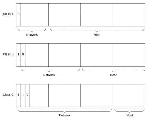
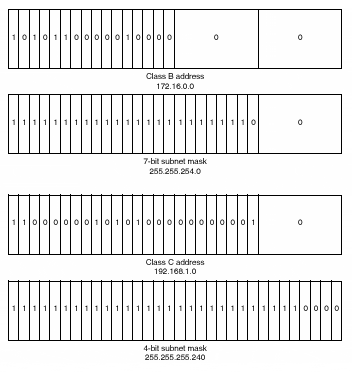
Figure 4-1 illustrates the address structure of network Classes A, B, and C. Figure 4-1. Classes A, B, and C Address Structure When converting an IP address from decimal to binary and determining how many of the high-order bits are set to 1, it is easy to see to which network class an address belongs. Assuming that there is no subnetting, knowing the class to which the address belongs tells us what portion of the address to read as the network portion and what portion to read as the host portion. Devices such as routers need to decipher this information to deliver data to the appropriate destination. If a network is subnetted, however, it is not possible to tell at a glance how much of the host portion of the address has been borrowed to make the subnet. To solve this dilemma, IP addresses also have a subnet mask (commonly referred to as the network mask). Like the IP address, the network mask is a 32-bit binary number, grouped into four octets, that can be expressed in decimal notation. Unlike the IP address, however, the network mask has bits set to 1 in all positions except for the host portion of the IP address. For example, a Class B network with no subnetting defined has a mask of 255.255.0.0, in which the upper 16 bits of the mask denote the network portion of the IP address and the lower 16 bits denote the host portion of the IP address. A Class B network in which seven bits of the host portion of the address have been used for subnetting would have a mask of 255.255.254.0. A Class C network with four bits of subnetting would have a mask of 255.255.255.240. Figure 4-2 shows the relationship between the network mask and the IP address. Figure 4-2. Sample Network Masks Subnetting gives network administrators the flexibility to assign a unique network identifier to each LAN and WAN segment without having to obtain a separate network address space for each. For example, instead of a single Class B network address having one logical network segment of more than 65,000 hosts, a subnetting scheme that borrows eight bits from the host component allows for 255 logical network segments of 255 hosts each. By pairing an IP address with its network mask, it is possible to determine exactly which bits of the address correspond to the network, subnet, and host components. For example, an IP address of 131.108.3.4 with a network mask of 255.255.0.0 has a network component of 131.108.0.0, a host component of 3.4, and no subnet component. An IP address of 131.108.3.4 with a network mask of 255.255.255.0 has a network component of 131.108.0.0, a subnet component of 3, and a host component of 4. With today's routing protocols carrying network mask information as well as network information in their updates, you can use multiple network masks within a single logical IP network to increase the efficiency of IP address utilization. The concept of the network mask has been extended beyond its original subnet usage. In response to the explosive growth of the Internet, the number of IP network addresses requested , the shortage of IP address space, and the size of the global IP routing table, the agencies that issue IP addresses might not issue IP addresses along the specified class boundaries described thus far. Instead, they might choose to group multiple IP network addresses of a given class into what is called a supernet, or a classless interdomain route (CIDR) block. Additionally, some of the former Class A networks have been subdivided and issued as smaller CIDR blocks to companies and ISPs. In the past, a company or ISP might have been issued a Class B network. Today, it might be issued 255 Class C addresses, ranging from 209.32.0.0 to 209.32.255.0. The natural network mask of these Class C networks ”with no subnetting within the block of addresses ”is 255.255.255.0. However, by shortening the mask and creating a supernet of these addresses, the same group of addresses can be represented by the network address 209.32.0.0 and network mask 255.255.0.0. The organization that receives an allocation of a CIDR block is then free to further subdivide that network address space as either subnets within their logical network or as allocations to their customers. This same method can be applied to the Class A addresses in reverse. Formerly, the network address 12.0.0.0 with a natural network mask of 255.0.0.0 would have to be assigned to one company or ISP. Now, this network address can be treated as a block of addresses, and smaller pieces can be allocated to multiple entities. For example, the group of addresses from 12.1.0.0 through 12.1.255.0 can be represented as a single CIDR block with network address 12.1.0.0 and a network mask of 255.255.0.0. By subdividing these formerly large network address blocks, larger numbers of IP network addresses have been made available, and address exhaustion has been slowed. Writing and describing network addresses as four dotted-decimal octets followed by a four- dotted -decimal octet network mask has always been somewhat cumbersome. A more precise and compact way of describing the address space was desired when assigning CIDR blocks of addresses. The creation of the classless IP network address system provided the network community with a new shorthand for writing IP network masks. In this shorthand, a forward slash, /, followed by the number of bits set to 1 in the network mask, is used instead of the four-octet dotted-decimal mask. A network mask of 255.255.0.0 has 16 bits of ones, so it can be written as /16 (pronounced "slash sixteen"). A network mask of 255.255.252.0 has 22 bits of ones, so it can be written as /22. This type of mask is known as a bit-count mask. Combined with an IP network address, the network shorthand of 131.108.0.0/16 can be used to represent 131.108.0.0 mask 255.255.0.0. Likewise, 206.220.224.0/22 can be used to represent 206.220.224.0 mask 255.255.252.0 (which itself is a CIDR block representing the Class C addresses 206.220.224.0 through 206.220.227.0, each with mask 255.255.255.0). Note During the system configuration dialog described in Chapter 2, "The Basics of Device Configuration," it is assumed that all network addresses fall along the classful network boundaries described earlier. The Number of bits in subnet field [0]: question that is posed to the user is asking how many bits of the host component should be used for subnetting based on the class of the network number the user entered. If the network number is a Class A network, such as 17.0.0.0, 24 bits of the host field could be used for subnetting. If the user indicates that nine bits are used for subnetting, the IOS calculates the appropriate network mask ”in this case, 255.255.128.0. |
EAN: 2147483647
Pages: 116

