Local-Area Network Technologies
| Cisco devices support multiple LAN technologies. We cover five popular technologies in this chapter:
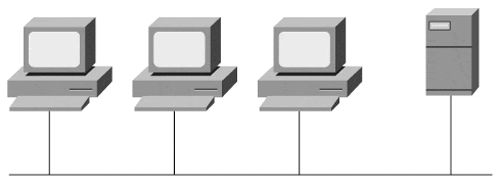
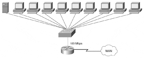
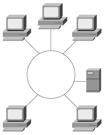
Each of these protocols operates at the data link layer of the OSI reference model, and each is used in a LAN environment to carry data from point to point at speeds from 4 Mbps to 1 Gbps. This section briefly introduces you to each of these protocols. If you want to learn about these protocols in depth, we have included additional references at the end of the chapter. All these LAN protocols share a common data link layer addressing scheme. The addresses are 6-byte are 6-byte hexadecimal addresses that are unique in the world. These addresses are called Media Access Control (MAC) addresses, also referred to as hardware, station, or physical addresses. This means that every LAN device in the world has a unique data link layer address. The address is burned into read-only memory (ROM) on the interface card itself. To ensure that each interface gets a unique address, each manufacturer is assigned a 20-bit prefix of the 6-byte address. For example, Cisco has been assigned the 20-bit prefix of 0060.5 (shown here in hexadecimal format, in which each digit represents 4 bits). The manufacturer can then assign the remaining 28 bits in any manner, as long as each address remains unique. The unique data link layer address for each Cisco LAN interface is seen in the show interfaces command output in the second line of output. The data link address for the Kuala Lumpur router from the ZIP network can be seen in the following output: Kuala-Lumpur> show interface ethernet 0 Ethernet0 is up, line protocol is up Hardware is QUICC Ethernet, address is 0060.5cbc.0ef9 (bia 0060.5cbc.0ef9) MTU 1500 bytes, BW 10000 Kbit, DLY 1000 usec, rely 255/255, load 1/255 Encapsulation ARPA, loopback not set, keepalive set (10 sec) ARP type: ARPA, ARP Timeout 04:00:00 Last input 00:00:00, output 00:00:01, output hang never Last clearing of "show interface" counters never Queueing strategy: fifo Output queue 0/40, 0 drops; input queue 0/75, 0 drops 5 minute input rate 1000 bits/sec, 1 packets/sec 5 minute output rate 1000 bits/sec, 1 packets/sec 116547 packets input, 13397137 bytes, 0 no buffer Received 3402 broadcasts, 0 runts, 0 giants 0 input errors, 0 CRC, 0 frame, 0 overrun, 0 ignored, 0 abort 0 input packets with dribble condition detected 273769 packets output, 84816409 bytes, 0 underruns 65959 output errors, 1 collisions, 1 interface resets 0 babbles, 0 late collision, 29 deferred 65959 lost carrier, 0 no carrier 0 output buffer failures, 0 output buffers swapped out Note It is technically possible for the IOS to use a different data link address on a given LAN interface than the burned-in address (bia) found in ROM. The practice of changing the bia for a LAN interface is rare, but it is useful in some complex network configurations. Ethernet and IEEE 802.3Ethernet and the Institute of Electrical and Electronic Engineers (IEEE) 802.3 protocol are the most common LAN protocols in use today. Ethernet was developed in the mid-1970s by researchers at the Xerox Palo Alto Research Center (PARC). Xerox, Digital Equipment Corporation, and Intel Corporation standardized it in 1978. Later, the IEEE standardized a similar protocol called IEEE 802.3. The uses of the frame fields between Ethernet and IEEE 802.3 differ slightly. Note Many IEEE protocols in this book start with the numbering scheme 802, signifying the year and month the original committee was formed . Both Ethernet and IEEE 802.3 use a network technology called carrier sense multiple access collision detect (CSMA/CD) to allow access to a common 10-Mbps bus on which all devices communicate. Multiple devices on a CSMA/CD bus can sense when there is traffic on the common bus (the carrier sense) and detect when two nodes talk at the same time (the collision detect). The CSMA/CD protocol also specifies how a device operates in the event of a collision. Logically, an Ethernet or IEEE 802.3 segment appears to be a single flat wire on which all devices are attached, as shown in Figure 3-1. Figure 3-1. An Ethernet Network Segment Ethernet or IEEE 802.3 devices can communicate in half-duplex mode, a mode in which the device can either send or receive a frame, but not both at the same time. Common Ethernet or IEEE 802.3 segments operate in half-duplex mode. Full-duplex Ethernet or IEEE 802.3 is where a device can send and receive a frame at the same time. Full-duplex mode is available only in a topology where only two devices are directly connected using Ethernet or IEEE 802.3, such as a device connected to an Ethernet switch. Cisco bridges and switches can be used to logically connect Ethernet and IEEE 802.3 segments using transparent, translational, or encapsulation bridging. In this environment, the Cisco device connects two or more LAN segments to make a single data link layer segment with separate CSMA/CD physical segments or collision domains. Figure 3-2 shows both the physical and the logical topology for an Ethernet segment, which is bridged and switched with Cisco devices. Figure 3-2. An Ethernet Network Segment Shown Physically (a) and Logically (b) You can use Cisco routers to separate Ethernet segments both logically and physically. Each Ethernet interface would have its own address, and the router would route packets based on network layer protocols between the interfaces. Fast EthernetThe broad success of Ethernet and CSMA/CD has recently led to the development of Fast Ethernet. Fast Ethernet is a CSMA/CD protocol that operates at 100 Mbps, which is ten times the speed of Ethernet and IEEE 802.3. The success of Fast Ethernet has been primarily due to the fact that the protocol can use the same physical media ( copper , twisted-pair, and fiber) as standard Ethernet, making it possible for many networks to migrate from 10 Mbps to 100 Mbps without changing the physical infrastructure. Because Fast Ethernet is a CSMA/CD protocol, the logical topology of a Fast Ethernet network is exactly the same as that of an Ethernet network. Also like Ethernet, Fast Ethernet can operate in half-duplex or full-duplex mode. Most Fast Ethernet devices can auto-matically detect whether the segment to which they are connected is Ethernet (10 Mbps) or Fast Ethernet (100 Mbps) and also can detect the appropriate duplex (half-duplex or full-duplex). Cisco devices have Fast Ethernet interfaces on bridges, switches, and routers. Fast Ethernet is often used on a switch as an uplink for Ethernet interfaces. A common topology would be to have a switch connect ten Ethernet segments to a Fast Ethernet segment, and then to connect the Fast Ethernet segment to a router for access to a WAN, as shown in Figure 3-3. Figure 3-3. An Ethernet Switch with a Fast Ethernet Uplink to a Router Fast Ethernet and Ethernet Interface Configuration SubcommandsOn some Cisco 4000 and 7000 series routers, each Ethernet and Fast Ethernet interface has a choice of media types for connecting to the router. Use the interface configuration subcommand media-type to tell the router which type of connection is active on the interface. In the following example, we set the media type for the Seoul-1 router: Seoul-1 #configure Configuring from terminal, memory, or network [terminal]? Enter configuration commands, one per line. End with CTRL+Z. Seoul-1(config) #interface ethernet 0 Seoul-1(config-if) #media-type 10baseT Seoul-1(config-if) #^Z Attachment unit interfaces (AUIs) and RJ-45 connectors (called 10BaseT by the IOS to signify twisted-pair wiring) are the valid media types for Ethernet and IEEE 802.3 interfaces. AUIs are 15-pin connectors. Media-independent interfaces (MIIs) and RJ-45 connectors are the valid media types for Fast Ethernet interfaces. On Fast Ethernet interfaces, you can manually set the duplex using the full-duplex interface configuration subcommand. If you remove this command with the no full-duplex command, the interface defaults to half-duplex mode. In the following example, we set the Fast Ethernet port on the Seoul-1 router to full-duplex: Seoul-1 #configure Configuring from terminal, memory, or network [terminal]? Enter configuration commands, one per line. End with CTRL+Z. Seoul-1(config) #interface ethernet 0 Seoul-1(config-if) #full-duplex Seoul-1(config-if) #^Z Gigabit EthernetSimilar to Fast Ethernet, Gigabit Ethernet (or IEEE 802.3z) builds on the IEEE 802.3 Ethernet standard. The main difference, as the name implies, is that Gigabit Ethernet communicates with devices at 1 Gbps. In the same way that Fast Ethernet is ten times faster than Ethernet and IEEE 802.3, Gigabit Ethernet is ten times faster than Fast Ethernet. However, unlike Fast Ethernet, the implementation of Gigabit Ethernet requires that changes are made to the physical interface on a device. From the data link layer and above on the OSI protocol stack, Gigabit Ethernet operates identically to Ethernet. At the physical layer, Gigabit Ethernet makes use of an interface type already in use by another high-speed LAN technology called Fiber Channel. Gigabit Ethernet combines the Fiber Channel physical layer and the data link layer frame format in use by IEEE 802.3, Ethernet, and Fast Ethernet. Gigabit Ethernet uses the CSMA/CD algorithm and can operate in half-duplex or full-duplex modes. IEEE 802.3x defines the standard for full-duplex Gigabit Ethernet. Cisco 7500 series routers and Catalyst 5500 series switches support Gigabit Ethernet interfaces. On the 7500 series routers, a single Gigabit Ethernet interface per slot is supported at the present time. If the Gigabit Ethernet interface is in slot 2 of the 7500 series router, it is known as Gigabit Ethernet 2/0/0 (slot/port adapter/port), as seen in the following example: Router> show interface gigabitethernet 2/0/0 GigabitEthernet2/0/0 is up, line protocol is up Hardware is cyBus GigabitEthernet, address is 0000.0ca4.db61 (bia 0000.0ca4.db61) Internet address is 10.0.0.2/8 MTU 1500 bytes, BW 1000000 Kbit, DLY 1000 usec, rely 255/255, load 1/255 Encapsulation ARPA, loopback not set, keepalive set (10 sec) ARP type: ARPA, ARP Timeout 04:00:00 Last input 00:00:00, output 00:00:01, output hang never Last clearing of "show interface" counters never Queueing strategy: fifo Output queue 0/40, 0 drops; input queue 0/75, 0 drops 5 minute input rate 2300 bits/sec, 2 packets/sec 5 minute output rate 3000 bits/sec, 3 packets/sec 116547 packets input, 13397137 bytes, 0 no buffer Received 3402 broadcasts, 0 runts, 0 giants 0 input errors, 0 CRC, 0 frame, 0 overrun, 0 ignored, 0 abort 0 input packets with dribble condition detected 273769 packets output, 84816409 bytes, 0 underruns 65959 output errors, 1 collisions, 1 interface resets 0 babbles, 0 late collision, 29 deferred 65959 lost carrier, 0 no carrier 0 output buffer failures, 0 output buffers swapped out Token RingToken Ring is a LAN technology developed by International Business Machines (IBM) and standardized as the IEEE 802.5 protocol. As the name suggests, the Token Ring protocol operates on a logical ring topology, not a bus topology such as Ethernet. Token Ring uses a protocol called token capture to grant access to the physical network medium. The Token Ring protocol has been implemented at two speeds, 4 Mbps and 16 Mbps. The algorithm is relatively simple to understand. A device on a Token Ring network must capture a special packet called a token. A token traverses the ring in a logical counterclockwise direction. If a device has data to send, and it sees the token pass by on the ring, it can capture the token. After a device has captured the token, it can transmit a frame around the ring. As the frame passes around the ring, the destination system copies the data in the frame. When the frame sent by the device arrives back at the original source, the source removes the frame and puts the token back on the ring. On 16-Mbps Token Ring networks, the source system releases a new token before receiving the data frame back using a feature called early token release. Unlike CSMA/CD, the token capture protocol avoids collisions altogether because only the device that has captured the token can transmit a frame on the Token Ring. Also, it is possible to calculate the maximum time that a device must wait before it can transmit a frame, making the token capture protocol deterministic. For some network applications, such as real-time transactions, this determinism is an important requirement for a LAN protocol. The logical topology of a Token Ring network is shown in Figure 3-4. Figure 3-4. Token Ring Topology Note The internetworking industry debates endlessly about the merits of CSMA/CD versus token capture. We do not want to enter into the religious fray, so no judgment about the relative merits of either protocol is given in this text. Currently, CSMA/CD clearly dominates the LAN protocol marketplace , regardless of the technical merits of CSMA/CD or token capture. The following output shows the EXEC show interfaces command for the Token Ring interface on the San-Jose router, slot 1, port 0: San-Jose #show interfaces tokenring 1/0 TokenRing 1/0 is up, line protocol is up Hardware is 16/4 Token Ring, address is 5500.2000.dc27 (bia 5500.2000.dc27) MTU 8136 bytes, BW 16000 Kbit, DLY 630 usec, rely 255/255, load 1/255 Encapsulation SNAP, loopback not set, keepalive set (10 sec) ARP type: SNAP, ARP Timeout 4:00:00 Ring speed: 16 Mbps Single ring node, Source Route Bridge capable Group Address: 0x00000000, Functional Address: 0x60840000 Last input 0:00:01, output 0:00:01, output hang never Output queue 0/40, 0 drops; input queue 0/75, 0 drops Five minute input rate 0 bits/sec, 0 packets/sec Five minute output rate 0 bits/sec, 0 packets/sec 16339 packets input, 1496515 bytes, 0 no buffer Received 9895 broadcasts, 0 runts, 0 giants 0 input errors, 0 CRC, 0 frame, 0 overrun, 0 ignored, 0 abort 32648 packets output, 9738303 bytes, 0 underruns 0 output errors, 0 collisions, 2 interface resets, 0 restarts 5 transitions In the previous output, notice that the interface is operationally up, the data link burned-in address (bia) for the Token Ring interface is on the second line, and the 16 Mbps ring speed for the interface is shown on the sixth line. Token Ring Interface Configuration SubcommandsUse the IOS configuration interface subcommand ring-speed to specify whether the Token Ring interface is 4 Mbps or 16 Mbps. All devices on a Token Ring need to operate at the same speed; mixed ring-speed configurations are not permitted by the protocol and may lead to an inoperable ring. If you choose to use the early token release feature on a 16-Mbps ring, all devices on the Token Ring must have this feature enabled. If any device (Cisco or another manufacturer) on a Token Ring is not enabled to do early token release, the entire ring does not use this feature. The IOS configuration interface subcommand early-token-release enables early token release on an interface. In the following example, we set a Token Ring interface to operate at 16 Mbps and to enable early token release: San-Jose #configure Configuring from terminal, memory, or network [terminal]? Enter configuration commands, one per line. End with CTRL+Z. San-Jose(config) #interface tokenring 1/0 San-Jose(config-if) #ring-speed 16 San-Jose(config-if) #early-token-release San-Jose(config-if) #^Z Fiber Distributed Data InterfaceThe Fiber Distributed Data Interface (FDDI) is another token capture LAN protocol. The ANSI X3T9.5 standards committee standardized the FDDI protocol in the mid-1980s. FDDI is similar to Token Ring, but instead of using a single-ring architecture, FDDI uses a dual-fiber ring that transmits data in opposite directions. FDDI uses only one ring, called the primary ring, during normal operation. FDDI uses the second ring, called the backup ring, when there is a failure on the primary ring. When there is a single break in the primary ring, the devices closest to the break enter wrapped mode and use the backup ring to form a loop to ensure that the FDDI ring is still complete, as shown in Figure 3-5. Figure 3-5. FDDI Topology in Normal Mode (a) and Wrapped Mode (b) Like Fast Ethernet, FDDI operates at 100 Mbps. Because of this high-speed bandwidth and its inherent redundancy, FDDI is often used as a high-speed uplink from a switch to a router backbone or is used as a campus backbone technology. Cisco bridges, switches, and routers support FDDI for transparent and translational bridging, switching, and routing network layer protocols. On the ZIP network, the San Francisco corporate offices are using FDDI to interconnect routers within a multilevel building. The output of show interfaces for an FDDI interface on the SF-Core-1 router is as follows : SF-Core-1> show interfaces fddi 0/0 Fddi0/0 is up, line protocol is up Hardware is cBus Fddi, address is 0000.0c06.8de8 (bia 0000.0c06.8de8) MTU 4470 bytes, BW 100000 Kbit, DLY 100 usec, rely 255/255, load 1/255 Encapsulation SNAP, loopback not set, keepalive not set ARP type: SNAP, ARP Timeout 4:00:00 Phy-A state is active, neighbor is B, cmt signal bits 008/20C, status ILS Phy-B state is connect, neighbor is unk, cmt signal bits 20C/000, status QLS ECM is insert, CFM is c_wrap_a, RMT is ring_op token rotation 5000 usec, ring operational 1d01 Upstream neighbor 0000.0c06.8b7d, downstream neighbor 0000.0c06.8b7d Last input 0:00:08, output 0:00:08, output hang never Last clearing of "show interface" counters never Output queue 0/40, 0 drops; input queue 0/75, 0 drops Five minute input rate 5000 bits/sec, 1 packets/sec Five minute output rate 76000 bits/sec, 51 packets/sec 852914 packets input, 205752094 bytes, 0 no buffer Received 126752 broadcasts, 0 runts, 0 giants 0 input errors, 0 CRC, 0 frame, 0 overrun, 0 ignored, 0 abort 8213126 packets output, 616453062 bytes, 0 underruns 0 output errors, 0 collisions, 4 interface resets, 0 restarts 5 transitions, 0 traces In the previous output, notice that the interface is operationally up, the data link burned-in address (bia) for the FDDI interface is on the second line, and the 100-Mbps bandwidth (BW) is shown on the third line. The physical properties of each fiber (Phy-A is the primary ring; Phy-B is the backup ring) are shown on the sixth and seventh lines. |
EAN: 2147483647
Pages: 116


