Frame Relay Components
Frame Relay WANs are made up of four functional components:
Access Router or Frame Relay Access Device (FRAD)
Local access loop to the service provider network
Frame Relay network switch access port (Link Management Interface [LMI] parameters are defined here)
Frame Relay virtual circuit between Frame Relay User Network Interface (UNI) switch ports
Each of these components is discussed in the following sections.
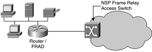
Frame Relay Router/FRAD
The Router/FRAD is located at the customer premise, shown in the Figure 10-2, and is either a dedicated FRAD or a router. Cisco routers can support multiple WAN interface cards (WICs), each connecting to a separate WAN, such as those provided by separate Frame Relay network service providers.
Figure 10-2. FRAD
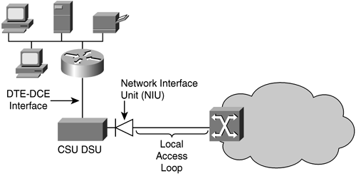
Local Access Loop
The local access loop is the physical wiring interconnecting the customer premise router/FRAD and the network service provider's Frame Relay switch access port. The local loop is one of the following types of services: DS0, DS1, NxDS1, DS3 service, or some fraction of DS1/DS3 service (for example, Frac-T1).
The local loop terminates into a Network Interface Unit (NIU) at the customer premise (see Figure 10-3), with subsequent connection to the customer data communication equipment (DCE) device, such as a channel service unit/data service unit (CSU/DSU). The data termination equipment (DTE) port of this CSU/DSU, often an RS-232/V.35 port, provides connectivity to the router/FRAD.
Figure 10-3. Frame Relay Local Access Loop
Frame Relay Virtual Circuits
A virtual circuit is a logical communications path between two physical devices, such as a Frame Relay switch/router. Frame Relay is a connection-oriented service using data-link connection identifiers (DLCIs) to identify the virtual circuit between the originating and terminating sites, as shown in Figure 10-4. This path, or virtual circuit, is a bidirectional logical (network-based) connection across the WAN between two end-nodes.
Figure 10-4. Frame Relay WAN with Virtual Circuit and DLCI
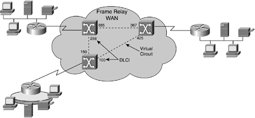
NOTESometimes the originating node of a virtual circuit is annotated as Site A and the terminating node of a virtual circuit is annotated as Site B or Site Z. |
The heart of a Frame Relay network is the virtual circuit, which can be either permanent (PVC) or switched (SVC). It is this virtual circuit that traverses the Frame Relay WAN backbone, interconnecting Frame Relay sites. DLCIs identify which virtual circuit a Frame Relay datagram (frame) must take to reach its intended destination.
DLCIs
DLCIs identify the PVC transporting the data traffic. DLCIs are of local significance, unless an agreement has been made with the network service provider to deploy global DLCIs. Local significance means that DLCIs are of interest to the local Frame Relay networking device; for example, the router or FRAD. Frame Relay DLCIs are analogous to an organization's telephone network using speed-dial functions. The most common deployment involves the use of local DLCIs because there is a network size limitation regarding the use of global DLCIs.
Technical Note: Global DLCI AddressesGlobal DLCI addresses are assigned so that each DLCI has universal significance, meaning that the DLCI number is pointed to the same destination (termination point) regardless of the origination point. The intent behind global DLCI addressing is to simplify frame relay network addressing administration; however, there is an inherent limitation with global addressing in that no more than 992 DLCIs can be used, which is 1,024 DLCIs less the 32 reserved DLCIs. In a Frame Relay network of more than 992 sites, global addressing will not work. Use of global DLCIs requires that each DLCI be preassigned (often these assignments are negotiated between the customer and the network service provider) and can be used only once throughout the network. (If two sites had the same DLCI, the network would not know which site is the intended destination). The Frame Relay switch within the service provider's network will have tables that route the traffic between each origination and termination pair. |
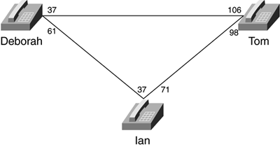
Suppose that an organization has deployed the following speed-dialing scheme (illustrated in Figure 10-5):
Ian speed-dials "37" to talk with Deborah.
Ian speed-dials "71" to talk with Tom.
Deborah speed-dials "47" to talk with Tom.
Deborah speed-dials "61" to talk with Ian.
Tom speed-dials "98" to talk with Ian.
Tom speed-dials "106" to talk with Deborah.
Figure 10-5. Telephone Speed-dial Network
The following table provides another view of this example Telephone Speed-Dial network.
Site A | Site B | A B Deborah | Tom | 37 | 106 |
|---|---|---|---|---|---|
Deborah | Ian | 61 | 37 | ||
Ian | Tom | 71 | 98 | ||
Ian | Deborah | 37 | 61 | ||
Tom | Ian | 98 | 61 | ||
Tom | Deborah | 106 | 37 |

In order for Ian to speak with Deborah, Ian will press speed-dial "37" on the telephone set. However, Deborah will see speed-dial "61" on the telephone because that is the local speed-dial assignment given to Ian. The speed-dial "37" local assignment on Deborah's telephone set is assigned to Tom.
If Deborah presses speed-dial "37," Tom will answer the phone; and speed-dial "106" will show on the Marketing VP's phone because that is the local assignment given to Deborah.
This same speed-dialing concept applies to Frame Relay DLCIs; the DLCI assignment is locally significant. The distant-end of the virtual circuit is unaware of this number because it has its own local DLCI assignment to identify the distant-end node. The DLCI local significance is illustrated in Figure 10-6.
Figure 10-6. Frame Relay Network with DLCI Assignment
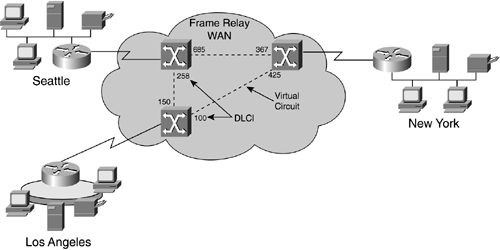
In this example, in order for Los Angeles to send traffic to New York, the Frame Relay Access Device (FRAD) will map the network layer information for example, the IP address to the Data-Link Connection Identifier (DLCI), which in this case, is 100. New York will see traffic arrive on DLCI 425 and will be able to identify within its Frame Relay mapping tables that this traffic has arrived from Los Angeles.
The following table provides a summary of the Frame Relay network shown in Figure 10-6.
Site A | Site B | A B Los Angeles | New York | 100 | 425 |
|---|---|---|---|---|---|
Los Angeles | Seattle | 150 | 258 | ||
Seattle | New York | 685 | 367 | ||
Seattle | Los Angeles | 258 | 150 | ||
New York | Seattle | 367 | 685 | ||
New York | Los Angeles | 425 | 100 |
DLCI values are discussed in further detail in the "Frame Relay Virtual Circuit Parameters" section later in this chapter.
PVCs
PVCs are permanently established virtual circuit connections; Frame Relay PVCs use DLCIs for connection addressing. PVCs, are used for frequent communication, such as file sharing, file transfer, and computer aided design/computer aided manufacturing (CAD/CAM) imaging between Frame Relay sites. PVCs operate in one of two modes:
Idle The connection between end-nodes is active albeit with no data transfer occurring. PVCs are not terminated or "taken-down" when in an idle state.
Data Transfer Data traffic is being transmitted between end-nodes over the virtual circuit.
Even though PVCs often are discussed as being full-duplex, PVCs are simplex connections, each with its own DLCI/CIR (committed information rate) assignment. For more information on DLCI/CIR assignments see the "Frame Relay Virtual Circuit Parameters" section later in this chapter.
NOTEThe three duplex modes are as follows:
|
Switched Virtual Circuits
Unlike PVCs, switched virtual circuits (SVCs) require a call setup process. SVCs are temporary connections used when communication between Frame Relay sites is infrequent or sporadic, such as Voice over Frame Relay (VoFr) applications.
NOTEFrame Relay SVCs use E.164 or X.121 addresses for connection addressing. |
The SVC call setup process is defined as follows:
Call setup Establishes the virtual circuit between Frame Relay end-nodes. Call setup includes negotiation of virtual circuit parameters, such as CIR.
Data transfer Data traffic is transmitted between end-nodes (originating and terminating) across the virtual circuit.
Idle When the virtual circuit is idle (no data traffic), the connection between end-nodes remains active and available for communication. Unlike PVCs, which do not terminate the connection, however, an SVC terminates the connection if it is in an idle state for a configured time period.
Call termination The virtual circuit between Frame Relay sites is terminated, or "taken down."
Frame Relay Virtual Circuit Parameters
Frame Relay Virtual Circuits, both PVC and SVC, have three configurable parameters that must be agreed upon between each site and the Frame Relay network service provider. For example, if the originating site is configured for one DLCI and the network service provider is expecting another, communication will not occur across the virtual circuit.
These parameters are as follows:
Committed Information Rate (CIR)
Discard Eligibility (DE)
Data-Link Connection Identifiers (DLCIs) for PVCs
X.121/E.164 addresses for SVCs
Frame Relay Committed Information Rate
The CIR is the amount of bandwidth that will be delivered as "best-effort" across the Frame Relay network backbone. Network service providers often have provisions in their tariffs guaranteeing delivery of CIR traffic at some percentage. For example, a tariff may state a guarantee delivery rate of 99.9 percent CIR-marked traffic.
CIR is measured in bits per second, over a period of time, expressed as TC. TC is often measured as one second. BC is the committed burst rate across the virtual circuit for that second (TC). Bc is represented by the following formula:
BC = CIR x TC
Bc is the maximum number of bits that a Frame Relay network is committed to accept and will transmit at the CIR. Traffic in excess of CIR is measured as Be (Excess Burst Rate). BE is the number of bits that a Frame Relay network will attempt to transfer after Bc is accommodated, and it is marked as Discard Eligible (DE). TC is the time period over which BC and BE are measured. The TC interval counter starts at zero when data begins to enter the Frame Relay network and ends when data is no longer entering the network. When a new data stream enters the network, the TC counter restarts at zero.
Frame Relay PVCs often are discussed as being two-way, but these PVCs are simplex (one-way) connections, each virtual circuit is configured with its own CIR. The Frame Relay network service provider provisions these PVCs in pairs: A  B and B A. This means that an A B PVC could be configured for 64 Kbps CIR, and a B A PVC could be configured with a 32 Kbps CIR. It is up to the network designer or engineer to determine the proper amount of CIR required, often based on user and application traffic.
Frame Relay Discard Eligibility
Frame Relay uses a bit in the frame header indicating whether that frame may be discarded in the event congestion is encountered during transmission. The Discard Eligibility (DE) bit can be set by the sending Frame Relay site to prioritize the frame to show that it has a lower priority than other outgoing frames. If the network becomes congested, frames with the DE bit marked will be discarded before frames that do not have the DE bit marked to relieve this network congestion.
The following flowchart (see Figure 10-7) illustrates the process each Frame Relay network service provider's switch runs when receiving a frame for transmission.
Figure 10-7. Frame Relay Data Frame Transmission Flowchart
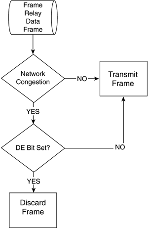
Discard eligibility means that in the event the frame encounters congestion while traversing the network, it is eligible to be discarded from the network, in part relieving the network congestion. Some networks take no action when the DE bit is set. When a DE frame is discarded, it is up to the upper-layer protocols, such as TCP (of the TCP/IP suite), to determine the loss and make corrective actions, such as retransmission.
NOTEThe DE bit can be used to determine which frames should be dropped first or which frames have lower time sensitivity. DE lists can be created within Cisco routers to identify those frames eligible for discarding, and DE groups can be specified to identify the DLCI that is affected. |
PVC DLCIs
DLCI values can be 10, 16, or 23 bits in length 10-bit DLCIs are the norm and have become the de facto standard for Frame Relay WAN implementations.
The 10-bit DLCI values, as recommended by the Frame Relay Forum, and are defined as shown in Table 10-3.
DLCI Value | Function |
|---|---|
0 | FRF In-channel signaling |
1 to 15 | Reserved |
16 to 1007 | Available for VC endpoint assignment |
1008 to 1022 | Reserved |
1023 | Local Management Interface (LMI) |
The 10-bit DLCI values, as recommended by both the ANSI (T1.618) and the ITU-T (Q.922) are defined as shown in Table 10-4.
DLCI Value | Function |
|---|---|
0 | In-channel signaling and management (LMI) |
1 to 15 | Reserved |
16 to 991 | Available for VC endpoint assignment |
992 to 1007 | Frame Relay bearer service Layer-2 management |
1008 to 1022 | Reserved |
1023 | Reserved for in-channel layer management |
NOTEThe number of DLCIs configurable per port varies depending on the traffic level. All 1000 may be used; however, in common use, 200 to 300 is a typical maximum. If the DLCIs are used for broadcast traffic, 30 to 50 are more realistic due to CPU overhead caused by broadcast generation. |
SVC X.121/E.164 Addressing
Where PVCs use DLCIs, Switched Virtual Circuits (SVCs) use X.121 for virtual circuit addressing. X.121 is a hierarchical addressing scheme and was originally designed to number X.25 nodes. X.121 addresses are up to 14 digits in length and are structured as follows:
Country Code: 3 digits
The first digit is a zone number that identifies a part of the world. For example, Zone 2 covers Europe and Zone 3 covers North America. These codes are found in ITU-T Recommendation X.121.
Service Provider: 1 digit
Terminal Number: Up to 10 digits
E.164 is a hierarchical global telecommunications numbering plan, similar to the North American Number Plan (NANP). E.164 addresses are up to 15 digits in length and are structured as follows:
Country Code: 1, 2, or 3 digits
This code is based on the international telephony numbering plan. (The international telephony numbering plan can be found in any phone book).
National Destination Code and Subscriber Number: Up to 14, 13, or 12 digits in length (maximum length depends on the length of the Country Code).
Subaddress: Up to 40 digits
NOTEITU-T is the designation for the International Telecommunications Union Telecommunications Standardization Sector. |
EAN: 2147483647
Pages: 269