LEC CO Configuration
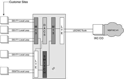
Local access circuits have two termination points: the customer premise and the LEC CO. Figure 6-7 illustrates a common CO infrastructure.
Figure 6-7. Typical Service Provider POP/CO Infrastructure

The equipment illustrated here is identified as follows:
Light Termination Equipment (LTE) Fiber-optic transmissions terminate here, often in the form of fiber or lightwave multiplexers (muxes). LTE can be used to terminate fiber-optic signals from a customer site or for interconnection of fiber-optic signals between LEC/IXC COs. LTE cannot terminate copper facility-based signals; M13's are used for these terminations.
Multiplexer DS1/DS3 (M13), pronounced "M-One-Three" Performs both multiplexing and demultiplexing functions. Multiplexes 28 DS1 signals into a single DS3 signal for transmission, often terminating to the LTE. Demultiplexes DS3 signals into 28 DS1 signals, often terminating into a DACS (DXC) or voice/data switch. M13s terminate copper-based signals; LTE (Fiber muxes) are used to terminate fiber-optic signals found in "fiber-to-the-curb" (FTTC) implementations.
Digital Cross Connect System (DACS or [DXC]) They electronically switch the DS0s within each DS1, or DS1s within each DS3. DACS can also be used to provide network timing for dedicated T1 service. Optical DACS are used to switch fiber optic signals, switching DS1/DS3s within higher bandwidth transport, such as OC-x (OC3, OC12, etc.).
Switch This could be a voice or data (ATM or Frame Relay) switch. The switch is an interface to the respective network for which it provides service, such as voice or data.
EAN: 2147483647
Pages: 269