LAN Hardware
Four hardware devices are used in LANs:
Hubs multiport repeaters. Hubs work at the Physical layer (Layer-1) of the OSI Model, repeating signals out of all hub ports.
Bridges multiport hubs. Bridges work at the Physical layer (Layer-1) of the OSI Model and operate at the Data-Link layer (Layer-2). Bridges forward data frames based on the destination MAC address using the spanning tree algorithm for path determination.
LAN switches multiport bridges. LAN switches connect common broadcast domains, providing frame-level filtering and dedicated port-speed to end-users. LAN switches create Virtual LANs, or VLANs. Like bridges, LAN switches use the spanning tree algorithm for path determination.
Routers found at the edge of a LAN providing the interface to a WAN, such as a Frame Relay network or the Internet. Routers operate at the Network layer (Layer-3) of the OSI Model.
Hubs
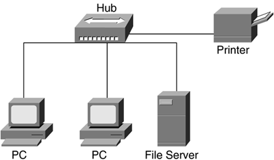
Hubs connect devices on one shared LAN, as illustrated in Figure 5-14. Because only two devices can be connected with LAN cables, a hub is needed to interconnect two or more devices on a single LAN. The cable termination points are the hub and the LAN device (host).
Figure 5-14. Hub-based Network

Hubs are not smart devices, meaning that they only repeat the data sent from a network host on one port to all other hub ports, without examining the data frame or the frame header. When network hosts are connected by a hub, each hubbed host will hear all conversations across the LAN. Each host examines the message header to determine whether it is the intended recipient.
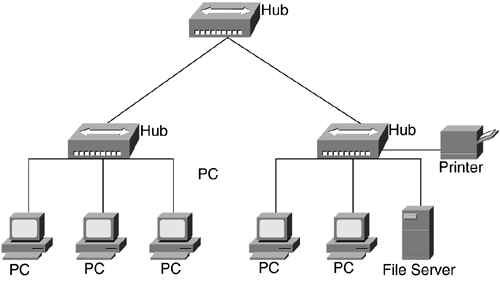
Backbone hubs are deployed to connect other hubs into a single termination, or root, point. This is known as a multi-tiered design and is illustrated in Figure 5-15.
Figure 5-15. Backbone, or Multi-Tiered, Hub Network

A couple benefits are derived from multi-tiered designs:
They provide interdepartmental connections between hubs.
They extend the maximum distance between any pair of hosts on the network.
Bridges
Bridges connect LAN segments, lengthening the diameter (across a distance) of the LAN as well as segmenting, or breaking up, collision domains. The four types of LAN bridging are listed here:
Transparent bridging Ethernet bridging (see Figure 5-16) connects two or more LAN segments and is transparent to end-devices.
Figure 5-16. Transparent Bridge Connecting Two Ethernet LAN Segments

Source-route bridging Token Ring bridging (see Figure 5-17) connects Token Ring LAN segments, whereby frames are sent from the originating host with the source-to-destination route, or path, included.
Figure 5-17. Source-Route Bridge (SRB) Connecting Two Token Ring LAN Segments

Source-route translational bridging Also known as mixed-media bridging, connects networks of two different media (see Figure 5-18), such as Ethernet and Token Ring.
Figure 5-18. Source-Route Translational Bridge Connecting One Ethernet LAN Segment and One Token Ring LAN Segment

Source-route transparent bridging Token Ring bridging (see Figure 5-19) that will either source-route or transparently bridge a frame depending on the Routing Information Indicator (RII) field.
Figure 5-19. Source-Route Transparent Bridge Connecting Two Token Ring LAN Segments

Cisco Note: Cisco Specific Bridging SolutionsCisco has developed five alternative solutions to the previously discussed bridging options. These five are as follows:
|
Spanning-Tree Protocol (IEEE 802.1d)
The Spanning-Tree Protocol (STP) is the protocol used in a bridged or switched environment enabling these devices (bridges and switches) to communicate LAN management information with each other. When multiple bridges or switches are interconnected with multiple paths, a looped topology can be formed. A looped topology often is desirable to provide redundancy, but looped traffic is undesirable and bridged traffic is especially vulnerable to broadcast loops. The STP, IEEE 802.1d, was designed to prevent broadcast loops from being formed. The STP originally was developed for bridges; however, today it also is applied to LAN switch topologies. By applying the STP to a looped bridged or LAN switch topology, all bridged segments will be reachable, but any points where loops can occur will be blocked.
Technical Note: Spanning Tree Port StatesThe IEEE 802.1d specification defines five port states (in order) for STP:
|
When a bridge or LAN switch port is activated, it proceeds through three spanning tree states: listening, learning, and forwarding. If the port is the highest cost path to the root bridge in a looped topology, it enters the blocking state. By default, all bridge ports go through the first two states: learning and listening. Based on the information obtained during these states, the interface enters either the forwarding or blocking state.
The spanning tree algorithm takes 50 seconds to calculate a new topology. The transition time for each state is as follows:
From blocking to listening 20 seconds
From listening to learning 15 seconds
From learning to forwarding 15 seconds
Latency, in addition to normal operation, is incurred when the ports go through the different states due to a network change, such as a failed path, addition of a new bridge or switch, or enabling a bridge or switch port. Cisco uses a default value of 15 seconds for the Forward Delay time, which is used to measure the time a port stays in a specific state.
Switches
LAN switches connect common broadcast domains and provide frame-level filtering as well as dedicated port speed to end-users. Some switches have limited routing capabilities and can provide Layer-3 routing functions at the most basic level. Some benefits of using switches are higher bandwidth to the desktop and ease of configuration. Switches are deployed often to replace hubs and bridges as more bandwidth-intensive applications are implemented within an organization.
NOTEVirtual LANs (VLANs) are implemented in switched environments and can keep broadcast traffic within a specific domain of network users. |
Switch Operations
Switches carry network traffic by receiving data frames from a source host (connected to a switch port) and forwarding these frames through a different switch port (based on the frame header information). Traditional Layer-2 switching works by looking at the Media Access Control (MAC) address information in the data frame's header and forward the data according to the switch, or Content Addressable Memory (CAM) table. If the switch looks at the MAC address information and cannot determine which port to send the frames, the switch will broadcast (flood) the frames out from all ports. This broadcast process is known as flooding and is used to determine the destination port of a host (based on the destination information in the frame header). When the destination address is found, the associated port information is added to the switching table for future reference.
Switches give network users the ability to transfer data traffic in a network environment without collisions or bandwidth contention. Deploying LAN switches in an existing network environment requires minimal configuration and no changes to existing wiring closets, hubs, LAN cabling, or NICs.
There are several types of switching technologies that enable quick and scalable network transmission.
Switching Types
These four types of LAN switching are found today:
Store and Forward Switching This is one of the two common types of LAN switching. A Store and Forward switch works by reading and copying the entire data frame into its buffers. The switch performs error checking, looks up the destination address in the MAC address table, and forwards the frame to the appropriate destination.
Cut-through Switching This is the other common LAN switching type. A Cut-through switch copies the destination address and a small portion of the frame into its buffers before checking for the destination address interface in its MAC address table. When the destination port is determined, the frame is sent out the appropriate switch port. Cut-through switching increases switching speed because the switch does not copy the entire frame to the switch buffers.
Fast Switching This is the process of copying data frames into a memory buffer. The switch determines the switching path to the destination port by looking up the location of the destination port in the fast-switching cache. After the destination host path is determined, subsequent data frames use that switching path, thereby reducing path determination time.
Layer-3 Switching This uses routing functions, such as network layer addressing. Switches can be configured like routers regarding an addressing mechanism, but are still bound by a flat-network addressing scheme (no hierarchical addressing is supported). Switches that operate at Layer-3 currently do not support special features such as path optimization and load balancing.
NOTELayer-3 switching differs from the traditional Layer-2 switching by enabling data frames to be switched based on network addressing information. Traditional Layer-2 switching will look at the frames for the MAC address information for the destination address. |
Routers
Routers are hardware devices that enable communications between networks. Routers are protocol-specific in that they must support the network-layer protocol used by each data packet. For example, for a router to support Internet connections, it must be able to support IP traffic; or for support of a Novell Netware implementation, the router must support IPX.
Routers often are found connecting a LAN to a WAN, such as a Frame Relay network or to the Internet. Routers can support multiple networks, limited only to the number of network interfaces (serial ports) that are available on the particular unit in question.
Routers are available in several sizes, for example:
SOHO (Cisco 700/1600 Series)
Small (Cisco 26xx Series)
Medium (Cisco 3600/4500 Series)
Large (Cisco 7x00 Series)
Very Large (Cisco 12000 Series)
Routers examine and evaluate each packet arriving from and/or sending to each of the networks to which the router is attached. The router decides which network provides the best path, or route, to the packet's intended destination. The router can make this decision because the router has direct knowledge about each network to which it is connected and the protocols each network supports.
Routers forward packets by maintaining a list of each network and its connected hosts. This list is called a routing table and is maintained (and updated) by the use of routing protocols. Routing protocols are a suite of protocols, such as Open Shortest Path First (OSPF); Border Gateway Protocol, version 4 (BGP4); or Routing Information Protocol (RIP). These routing protocols each use a different method to learn the routes to networks and hosts. In the event there are multiple routes to a specific network/host, each routing protocol uses a different algorithm to determine which route is the best choice to the targeted destination network/host.
EAN: 2147483647
Pages: 269