Hierarchical Network Model
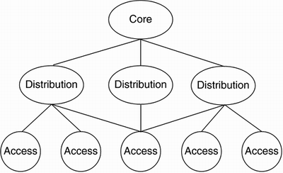
Network architecture is broken down into a three-tiered hierarchical model, as illustrated in Figure 14-5.
Figure 14-5. Three-tiered Hierarchical Network Model

The following lists the three layers, or tiers, in the three-tiered hierarchical network model:
Core The backbone layer providing (optimal) transport between sites
Distribution The layer providing policy-based connectivity
Access The layer providing site/user access to the network
These three layers core, distribution, and access need not exist in a clear and distinct physical fashion. These layers are defined to aid in network design, representing the network functionality that must exist. Each layer can exist in distinct and separate router or switch deployments, physical media, or they can be combined into a single device. For example, a Cisco Catalyst 6000 Series Switch can provide services for all three layers; the core layer is represented by the Multilayer Switch Feature Card (MSFC), providing WAN functionality. The distribution layer is represented by the switch backplane, and the access layer is represented by each switch port.
Core Layer
The core layer is the high-speed switching backbone designed and engineered to move packets through the network as quickly as possible. The core layer should not perform any manipulation of packets because the flow of packets would be slowed. An example of packet manipulation is access-list filtering.
NOTEAccess lists can be configured for all routed protocols, such as IP, IPX, or AppleTalk. They are used to prevent certain traffic from entering or exiting a network. |
Some examples of Cisco equipment often found in the core layer are as follows:
Cisco 720x Series Routers
Cisco Catalyst 6000 Series Switches
The following features enable core (backbone) services in a hierarchical network:
Path Optimization A logical environment where optimal traffic paths are selected based on routes learned from configured routing protocols. The key in selecting which routing protocol to implement often depends on how quickly the routing protocol can converge when there is an issue in the network backbone.
Traffic Prioritization The router prioritizes traffic flows, enabling policy-based routing and ensuring that mission-critical traffic takes precedence over other less time-sensitive traffic. Traffic prioritization is different from quality of service (QoS) in that traffic prioritization determines which traffic leaves the router first and QoS guarantees the bandwidth for that traffic across the network backbone.
Traffic prioritization is enabled through the implementation of one of the following queuing algorithms:
- - Priority Queuing Enables network administrators to prioritize traffic. Priority classifications are high, medium, normal, or low.
- - Custom Queuing Enables network administrators to ensure that each protocol is ensured a minimum level of service, preventing higher priority traffic from dominating a network link. A maximum of 16 queues can be built with custom queuing, enabling the network administrator to assign a percentage of network bandwidth to each protocol.
- - Weighted Fair Queuing Uses the time-division multiplexing (TDM) model to divide available network bandwidth among all protocols using the interface. Queues are serviced in a round-robin fashion, with each queue getting a fair share of network bandwidth (if every queue has the same weighting). Weighting enables a network administrator to ensure time-delay-sensitive traffic is guaranteed bandwidth leaving the router (entering the WAN), providing consistent response time under heavy traffic loads.
- - Priority Queuing Enables network administrators to prioritize traffic. Priority classifications are high, medium, normal, or low.
Load Balancing/Sharing Routers provide built-in load balancing for up to four paths to a destination network. Some routing protocols require that each path have an equal cost metric. Load balancing implies that each path has identical metrics so that there is no differentiator; in an NSP environment, this is not always possible. To emulate load balancing, equal cost load sharing is implemented, providing network administrators a way to adjust the cost metrics so that each router believes each path to be equal and identical.
NOTE
In networking, load refers to the amount of data (traffic) being carried by the network. Load sharing is the sharing of network traffic across multiple network connections, but not necessarily an equal load; for example, 65 percent of the load might traverse one network link and the remaining 35 percent would then traverse another link. Load balancing is the equal sharing of network traffic across multiple network connections 50 percent load across two links, 33.3 percent load across three links, etc.
NOTE
Cisco's IGRP and EIGRP provide unequal-cost load balancing.
Alternative Paths These are redundant network links that are available for use when primary end-to-end network links are unavailable.
Switched Access Provides the capability to enable a WAN link on an as-needed basis through automated router functions. Switched links often are used as dial backup lines for network sites. These dial backup lines are carried by the public switched telephone network (PSTN) and can automatically be established by the router using Cisco's Dial-on-Demand Routing (DDR).
Figure 14-6 illustrates an end-to-end dial backup implementation between two network sites.
Figure 14-6. Switched Access DDR

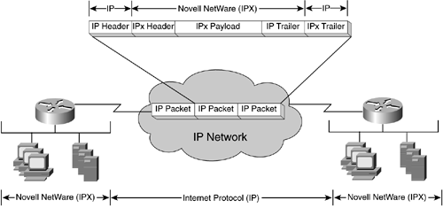
Encapsulation (Tunneling) Takes packets/frames from one network system and places them inside packets/frames from another network system, as illustrated in Figure 14-7.
Figure 14-7. IPX Tunneled Through an IP Network

For example, if Internet Protocol (IP) is used for network transport, but IPX is used on the LAN on each side, the IPX traffic is tunneled through the IP network by having each IPX packet encapsulated by an IP packet.
Encapsulation is the solution to use when multiple protocols need to traverse a single protocol backbone; for example, when AppleTalk and IPX users at multiple sites are interconnected by an IP backbone.
Distribution Layer
The distribution layer is the demarcation point between the core and access layers, helping define and delineate between network access and backbone functions. The distribution layer provides policy-based connectivity in the form of packet manipulation services for the core layer, such as access-list filtering. The distribution layer also provides for the following services:
Network address aggregation/summarization
Departmental workgroup access
Broadcast/Multicast domain definition
Virtual LAN (VLAN) routing
Network media transition/conversion (such as Frame Relay access to an ATM backbone)
Network security services (such as firewall services)
Some examples of Cisco equipment often found in the distribution layer are as follows:
Cisco 450x Series Routers
Cisco 36x0 Series Routers
Cisco Catalyst 400x Series Switches
Cisco Catalyst 35xx Series Switches
The following features enable distribution services in a hierarchical network:
Backbone Bandwidth Management Enabled by router performance tuning features, such as priority queuing, custom queuing, weighted fair queuing, and routing metrics.
Area and Service Filtering Traffic filters based on area or service are the primary tools used at the distribution layer to provide policy-based access control into the network backbone (core). These filters are used to enforce the selective sending of traffic based on network address, such as IP or IPX address, or specific protocol services, such as Simple Mail Transfer Protocol (SMTP) or HTTP (Web browsing) services.
Policy-Based Distribution Based on the premise that different groups or departments within an organization might have different traffic dispersion policies based on a set of rules implemented by the network administrator. These policies often are implemented to minimize unnecessary traffic from being sent into the network backbone.
One of the more common policy-based implementations is found in Novell NetWare implementations where Novell's Service Advertising Protocol (SAP) broadcast traffic is contained to the LAN and is not carried across the WAN.
Gateway Services Part of each router's standard software implementation. Gateway services enable a router to connect to multiple networks with different network addressing and facilitate communication between these network hosts by translating the network address as necessary.
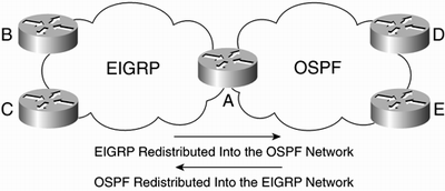
Route Redistribution Routers can provide gateway services for routing protocols, redistributing information from one routing protocol into another. For example, Figure 14-8 illustrates a routing redistribution that interconnects two networks.
Figure 14-8. Routing Protocol Redistribution

In the figure, one network is using Open Shortest Path First (OSPF) as its routing protocol, and the other is using Enhanced Interior Gateway Routing Protocol (EIGRP). In order for the OSPF routed sites (D and E) to communicate with the EIGRP routed sites (B and C), router A must redistribute routes from each network into the other so that Routers B and C can "see" Routers D and E, and vice versa.
Media Translation Translates frames from one network system into frames of another, such as translating frames between an Ethernet and a Token Ring network, as illustrated in Figure 14-9.
Figure 14-9. Media Translation

The router here is providing translation between Ethernet and Token Ring LANs, specifically between the Ethernet Transparent Bridging (TB) and the Token Ring Source-Route Bridging (SRB). Without the router between and connecting these two networks, users and network resources on either LAN would not be able to internetwork with each other.
Access Layer
The access layer is the point of entry into the network for local users. The access layer also can provide for policy-based services, such as access-list filtering. The access layer also provides for the following services:
Bandwidth sharing
Bandwidth switching
MAC layer filtering
Micro-segmentation
The following list provides some examples of Cisco equipment often found in the access layer:
Cisco 260x Series Routers
Cisco 170x Series Routers
Cisco Catalyst 25xx Series Switches
The following features enable access services in a hierarchical network:
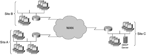
Value-Added Network Addressing Uses protocol specific helper-addressing to ensure that traffic is sent through a network that might not otherwise carry the traffic, as illustrated in Figure 14-10. Site C hosts the Dynamic Host Configuration Protocol (DHCP) server for Site A and Site B, without the use of a helper-address. LAN users at Site A and Site B would not be configured with an IP address because the router at these respective sites would not forward the DHCP request to Site C, because DHCP is a broadcast, which routers do not forward without a helper-address.
Figure 14-10. DHCP with Helper-Address

When DHCP is used, each LAN workstation is assigned an IP address when powered on and booted up. This LAN workstation sends a DHCP broadcast across the network requesting an IP address. If the DHCP server is on the same LAN, the request is received and an IP address is sent back to the requesting LAN workstation. If the DHCP server is on another network, however, the request will not be seen because routers do not forward broadcasts; routers break up broadcast domains by not forwarding broadcast traffic across the network. The helper-address tells the router that if certain broadcast traffic is received in this case, DHCP traffic it should be forwarded to a specified address.
Network Segmentation Splits a network into smaller, more manageable pieces (segments). Local-access routers implement local access policies limiting unnecessary traffic from traversing the network, consuming network bandwidth and other resources.
Broadcast/Multicast Capabilities Routers stop the propagation of broadcasts across a network, but can be configured to forward both broadcasts and multicasts to a single network address or group of network addresses. Broadcasts are messages sent to all network destinations; multicasts are messages sent to a specific group of network destinations.
Naming, Proxy, and Local Cache Capabilities Three key router capabilities reducing network traffic. Routers can act as Domain Name System (DNS) servers, resolving network names to network addresses (for example, resolving www.cisco.com to 198.133.219.25). Routers can act as proxy servers for a name server and as a name cache for NetBIOS implementations.
Media Access Security Routers keep local traffic from reaching the network backbone and keep network backbone traffic from entering into a local department or workgroup network, preventing possible security violations and inappropriate file and resource access.
Router Discovery The process of finding routers in a network by a LAN host. The following are router discovery protocols:
- - Routing Information Protocol (RIP) A routing protocol common on IP hosts. Many hosts use RIP to find the address of a router on a LAN.
- - Address Resolution Protocol (ARP) Uses broadcast messages to determine the MAC-layer address of an interface based on a known network address. For example, a host knows the router's Ethernet interface is 10.52.217.16, but does not know the MAC-address (required for Ethernet addressing). The LAN host sends an ARP (broadcast) request, destined for 10.52.217.16. The router will receive this request, recognize it is the intended recipient (based on the IP network address), and respond to the requesting host, thereby providing the requested MAC address of the router's interface.
- - Routing Information Protocol (RIP) A routing protocol common on IP hosts. Many hosts use RIP to find the address of a router on a LAN.
EAN: 2147483647
Pages: 269