Designing and Installing a Home Telephone System
Designing andInstalling a Home Telephone System
In this chapter, you will learn about
- Residential telephone design considerations
- Standard phone line installation hardware and termination points
- Telephone system installation hardware and termination points
- Intercom installation
The primary considerations when designing a residential telephone and telecommunications system are meeting the client’s needs and integrating the telephone system and its wiring into the structured wiring, data network, control system, and other whole house systems.
In this chapter, we discuss design considerations and installation activities for the structured wiring installation for both standard phone lines and a phone system.
Residential Telephone Systems Design
The design process for a residential telephone system using structured wiring must address the inclusion and placement of the telecommunication wiring schemes, outlet boxes, wire termination, jacks, punchdown blocks, patch panels, wire identification and labeling, and, of course, the telephone key sets (specialized phones designed to work with the key system unit).
| CROSS-REFERENCE |
See Chapters 5 and 6 for more information on structured wiring. |
Wiring Schemes
Telephone system wiring is typically installed using one of two schemes: series wiring or star (also know as home run) wiring. The star wiring scheme is the basis of a structured wiring approach and is always recommended for new construction or complete retrofit installations. Unfortunately, series wiring is common in older existing homes.
Series Wiring
Before 1980, series wiring was the standard wiring scheme used by telephone companies to install residential telephone service. The series-wiring scheme is also referred to as daisy chain wiring because the wiring is installed by running wires from one contact to the next. However, in situations where the telephone wiring must be reconfigured to accommodate more central office (CO) lines or more than three or four extension telephones, series wiring can be very restrictive.
Perhaps the best way to plan for a new telephone system around series wiring is to insert a punchdown block or patch panel at a point that creates separate runs to each room or zone of the house. Figure 27-1 shows a simplified drawing of series wiring in a house. In this case, the telephones (perhaps more than would be normally found in a home, but included to make the point) are wired in a daisy chain from the single connection in the network interface device (NID). Figure 27-2 shows a possible rework for the telephone system incorporating a Key Service Unit (KSU) phone system.
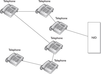
Figure 27-1: A telephone system using a serial wiring approach
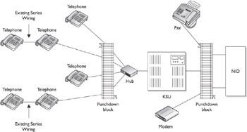
Figure 27-2: A series wiring system reconfigured into a star wiring approach
| CROSS-REFERENCE |
See Chapter 26 for more information on KSU systems. |
Star Wiring
A star wiring approach (see Figure 27-3) for a residential telecommunications system runs telephone wiring from each phone jack in the rooms of a house to a central point that is usually located near the demarc (demarcation point) or NID where the line or lines from the Telco’s CO arrive at the house.
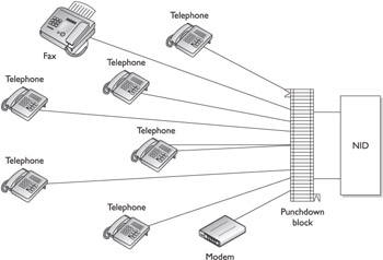
Figure 27-3: A basic star-wiring scheme for a telephone system
Running a separate run of four-pair Cat 5 unshielded twisted-pair (UTP) wire to each telephone outlet jack provides flexibility in terms of which incoming CO lines are linked to which phones. In situations where only a single CO line comes into a house, the choices may be to make some outlets only intercom stations and give access to the CO line to others. However, should more CO lines be added to the system at some point, using a punchdown block or a central telephone system control device, such as a KSU or digital control unit, makes it easy to configure which outlets have access to which CO lines as necessary.
Horizontal Wiring
Because the wiring inside a house, meaning all of the wiring beyond the demarc, is the responsibility of the homeowner, it is important to use only wiring that is category verified and carries a Underwriters Laboratories, Inc. (UL) marking on its outer jacket. Category verified wiring meets or exceeds industry fire, electrical, and materials specifications and also meets local building codes.
The current industry standards and recommendations specify a minimum of UTP Category 3 wiring for residential voice applications, although many new construction installations now use Cat 5e wiring in its place. Category 3 cable consists of four twisted pairs of 100-ohm, light gauge (typically 22 or 24 AWG copper wiring), as does Cat 5e.
Standard Phone Line Installation
Installing a residential telephone system in a new construction situation involves installing four basic elements: structured wiring, outlet jacks, punchdown or distribution blocks, and phone devices.
Telephone Wiring
When working with the wiring installed by the telephone company, you may find one or more of the following wire and cable types:
- 25-pair cableThis is a gray-, beige-, or pink-jacketed cable that contains 25 pairs of twisted wire, as shown in Figure 27-4. Although this large of a cable is unusual in residential situations, some older large homes have been known to have a 25-pair cable connected to the demarc using an RJ-21 50-pin connector, commonly called an Amp (short for Amphenol) Champ. RJ-21 connectors are used to connect this size cable to punchdown blocks and other types of distribution panels.

Figure 27-4: A 25-pair UTP cable cut-away to show the internal wire-pairs - Satin cordSo called for its silver coating, this flat cable has 4 untwisted 26 gauge wires, has either RJ-11 (shown in Figure 27-5) or RJ-45 jacks, and is used to connect a wall outlet to a telephone set.
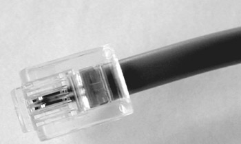
Figure 27-5: A terminated satin cord - Station wireMany existing residential telephone systems use station wire, which consists of 4 24-gauge solid-core wires (see Figure 27-6) that are twisted together into 2 wire pairs—1 consisting of red and green wires and 1 consisting of yellow and black wires. This type of wire is also called plain old telephone service (POTS) wire. Newer types of station wire is made up of blue and orange wires banded with white in which one pair is blue/white and orange/white and the other pair is white/orange and white/blue.
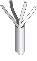
Figure 27-6: A piece of station wire, stripped to show its internal wires
Structured Wiring for Standard Telephone System
Chapters 5 and 6 detail the requirements for installing structured wiring. However, as far as support for a telephone system in the structured wiring goes, there are some product specifications and handling issues you will need to consider.
Standard Phone Outlet Wiring
Four-pair UTP Cat 3 minimum wiring (Cat 5e recommended for future-proofing) should be installed between a location near where the demarc can be easily reached. The wire pairs provide the capability to connect up to a combination of four phone, digital subscriber line (DSL), fax, or modem lines to inline locations in the house, as illustrated in Figure 27-7.
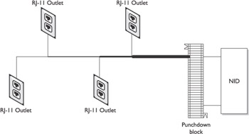
Figure 27-7: Cat 5e wiring installed to provide connections to four outlets
Cable
If a structured wiring installation is to support only a telephone system, only a four-conductor cable, such as station wire, is required and category-rated cabling isn’t needed. However, installing Cat 5e cable to each outlet of the telephone system helps to future-proof the system. If structured wiring is being installed to support audio, control, video, and other whole-house applications, it may be better to install composite cable that includes all of the various wire types needed to support each of a home’s subsystems, as well as provides for future cable requirements.
The wire elements included in common composite cables are typically two or more runs of either Cat 5e or Cat 3 UTP and one or more runs of coaxial cable. Figure 27-8 illustrates the makeup of one type of residential structured wiring cable.
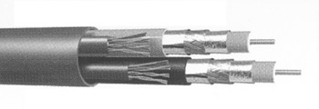
Figure 27-8: Composite structured wiring cable with two runs each of Cat 5e and coaxial cable
In most instances, installers choose to use one of the Cat 5e cabling in a composite cable for voice delivery and the other Cat 5e for data networking.
Punchdown/Distribution Blocks
Structured wiring concepts involve a central distribution point that serves as both the center of the star topology and a single testing, maintenance, and configuration location. A cable interface, patch panel, or punchdown block, also called a cross-connect block, is typically used as the distribution point in structured telephone wiring installations. If a structured pre-wiring system is in use in the home, then the telephone lines will terminate in the central service unit of that system.
| CROSS-REFERENCE |
See Chapter 7 for information on the different types of distribution panel connectors. |
Distribution PanelsThere are several models of telephone system distribution panels made especially for, and incorporated into, residential telephone systems. Residential phone distribution modules simplify the wiring for a home telephone system because they include features such as already in-place bridging for up to 4 CO lines to 12 or as many as 48 telephone outlets, 110-style punchdown or RJ-style connectors in and out, and wall-mount kits. Most of these systems also satisfy the requirements for home distribution devices as required by the Electronic Industries Alliance/Telecommunications Industry Association (EIA/TIA) 568 and 570 wiring standards.
For many residential installations, an RJ-11 patch panel makes more sense than using a punchdown patch panel to create the cross-connect between the CO line entrance cables and the Cat 3 or Cat 5 cable runs to the RJ-11 outlets. Most homeowners are not technical and should the need arise to talk a customer through a line change for testing purposes, it is much easier to explain how to move an RJ-11 jack than a punchdown or pole and screw connection.
A home patch panel, such as the one shown in Figure 27-9, incorporates 110-type punchdown connectors that link a CO line to distributed RJ-style connectors are connected to the cabling that runs to the outlets. There are also patch panels available that have RJ-style connectors for both incoming and outgoing connections.
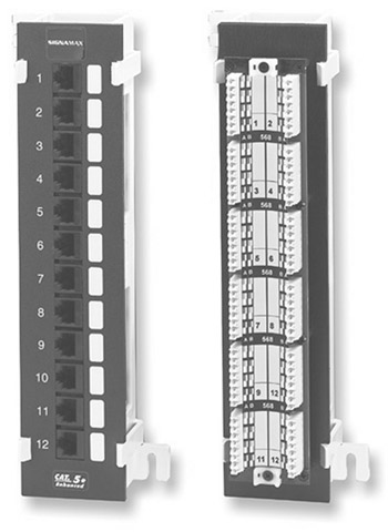
Figure 27-9: The two sides of a Cat 5 patch panel showing the IDC connections on the back and either RJ-11 or RJ-45 connectors on the front
Photo courtesy of Signamax Connectivity Systems.
Connecting to the Demarc
Once the pre-wire stage is completed and the horizontal wiring is pulled into where the central distribution panel is located, the next step in completing the telephone system wiring is to bridge the demarcation point to the outlet wiring runs. As we discussed above, this bridge is created using either a distribution panel or a patch panel.
Demarc to Patch PanelThe simplest way to connect the demarc point or the NID into the distribution point is to terminate a single run of Cat 5 wire with an RJ-11 jack and plug it into the customer-access side of the NID. A single run of Cat 3 or Cat 5 wire accommodates up to four incoming CO lines. The four pairs of wire in the Cat 3/5 wire are then terminated into the distribution panel, which for this discussion is an RJ-11 patch panel with 110-type punchdown blocks.
For testing purposes, it is always best to terminate the wiring from the demarc/NID at standard phone jacks at the phone system location. This allows for testing of each phone line inside of the house before the phone system. If there is a problem with one or more phone lines, this rules out the phone system as the cause of the problem.
| Note |
It is always advisable, especially if there is a phone system or security system, to run the cable of each phone line from the NID through a surge suppressor before connecting it into the distribution panel. Many structured wiring panels have built-in surge suppressors to protect alternating current (AC) electrical outlets, coaxial cable outlets, and RJ-11 outlets. |
Distribution Panel to OutletsThe cable installed during pre-wire for the telephone outlets should be terminated with the appropriate RJ-style outlets in the rooms of the house and into the distribution panel so that each outlet is bridged to the appropriate CO line, per the homeowner’s wishes.
Depending on the type of telephone system you are installing, the outlet jacks can be a standard telephone (RJ-11) or an RJ-45 outlet that supports a KSU/telephone system or an IP-based telephone system. Since RJ-11 jacks fit in both RJ-11 and RJ-45 outlets it is advisable to always install RJ-45 outlets to accommodate both standard phone and future phone systems.
Outlet jacks are typically color-coded and are either a 66- or a 110-punchdown connector; the 66-type is more common with telephone equipment and the 110-type is more common with networking devices. If the outlet is a standard phone jack, the red and green pins are used to enable line one and if a second line is being connected to the jack, line two is connected to the yellow and black pins. If you are using a data jack (RJ-45), the blue colored pins are connected for line one and the orange pins are used for line two, if needed.
Telephone to OutletIf the phone cords aren’t already terminated or you decide not to purchase already terminated cords, you may need to terminate the cords with RJ-11 plugs. A variety of manufacturers now make self-terminating jacks for RJ-11 and RJ-45 outlets that eliminate the need for wire striping, untwisting wires, and the use of a punchdown tool.
Table 27-1 lists the pinouts for RJ-style plugs typically used to terminate Cat 3 or Cat 5 cable. Figure 27-10 compares 4-pin RJ-11 and 6-pin RJ-11/12 jacks.
|
Signal |
Cat 3/5 Wire Color |
RJ-11/12 6-Pin |
RJ-11 4-Pin |
|---|---|---|---|
|
Line three (Tip) |
White/green |
1 |
|
|
Line two (Tip) |
White/orange |
2 |
1 |
|
Line one (Tip) |
White/blue |
3 |
2 |
|
Line one (Ring) |
Blue/white |
4 |
3 |
|
Line two (Ring) |
Orange/white |
5 |
4 |
|
Line three (Ring) |
Green/white |
6 |
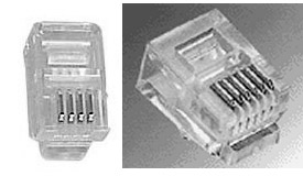
Figure 27-10: A 4-pin (left) and a 6-pin (right) version of the RJ-11 plug
| Note |
The terms “Tip” and “Ring” are used in telephony to indicate the pins and wires that carry positive and negative voltage. These terms come from the old switchboard plug-in where the positive voltage was connected to the tip of the plug and the negative voltage was connected to a slip ring that was around the plug. |
Telephone Outlets
Communications outlets are placed at the same height as the electrical outlets in a room, but no closer than one foot from an electrical outlet horizontally. If a room has a wall phone, its outlet should be mounted at about eye level, between 48 and 52 inches, on a wall. Wall phones require special outlet wall plates to support the physical phone on the wall.
Modular JacksModular jacks are common in older and most existing homes. This type of jack is surface mounted and provides connections for up to two communication lines on a single jack. Figure 27-11 shows the common modular jack design.
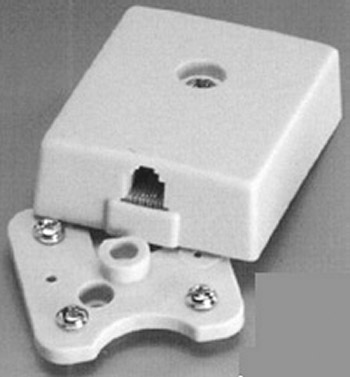
Figure 27-11: A modular RJ-11 telephone jack
Outlet Wall Plates and JacksFlush-mounted wall outlet jacks, like the one shown in Figure 27-12, are more common in today’s newer homes. Wall jacks are available with one, two, and up to six jack configurations.
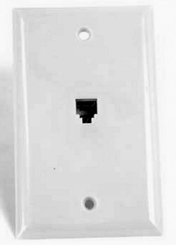
Figure 27-12: A surface- mounted RJ-11 wall jack
Typically, each of the individual jacks in a wall jack has either a 110-type connector or a RJ-11/12 style connector to receive and terminate the incoming telephone wiring.
Installing a KSU Telephone System
An alternative to installing a standard telephone system, in which many services, such as voicemail, caller ID, and call-waiting are provided as subscribed services by the telephone company (Telco), is installing a KSU system. A KSU-based telephone system has its own separate controller (the KSU itself) that can independently provide many of the same Telco subscriber services to specialized and/or standard telephones in the home.
The features typically provided by a residential KSU system include the capability to connect to standard telephones (and not proprietary key stations like many business KSU systems), voice-messaging (voicemail), station-to-station intercom support, auto-attendant, music-on-hold, caller ID, and in many cases, support for a door intercom.
Not every home needs or can afford a KSU telephone system, but in those homes with several phone lines and multiple extensions that desire these features and perhaps a few more, a KSU may be a very good value.
Installing the KSU
The KSU or controller of a KSU system (see Figure 27-13) should be treated like any central control unit and placed in a central location within the home, very near where the telephone line wire runs terminate. The commonly used method for connecting the KSU to the cable homeruns that are linked to the telephone outlets throughout a home is to terminate the cable runs into a 66-type punchdown block that bridges the cable runs to patch cords (also called pigtails) to the KSU using 25- or 50-pin Telco-type connectors (see Figure 27-14).
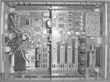
Figure 27-13: A KSU for a residential telephone system
Photo courtesy of NEC Corp.
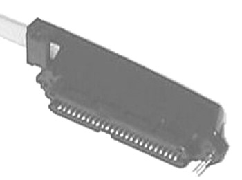
Figure 27-14: A 25-pin Telco connector is used to connect the internal phone wiring to a KSU.
The KSU should also be located fairly close to the connection for the Telco lines entering the home. In most cases, KSUs have RJ-11 jacks to connect to as many as eight incoming phone lines. The KSU should have a clean AC power source, preferably with a surge suppressor installed inline between the KSU’s power supply and the AC outlet.
Programming
In most cases, a KSU telephone system is preprogrammed for most of its basic functions for a certain number of stations. However, some adjustments may be required to set the clock, program speed dials, or add additional phones or features. Depending on the changes required, the programming manuals for the system should detail the process used to affect these changes. Some KSUs can be programmed through a system phone, or they provide an interface for connecting to a computer system or a terminal; in this case, changes are entered through software on the KSU. In other cases, some form of user interface, such as a liquid crystal display (LCD) and a keyboard, may be included on the KSU itself.
Planning for KSU Programming
The homeowners decide which features should be configured on the KSU system. Prior to beginning any programming changes or station configuration, you should summarize the system’s features on a worksheet that details the number of telephones to be installed and the features available to each telephone. Table 27-2 shows a portion of a sample worksheet that could be used to record the KSU system’s features the homeowners desire.
|
Unit |
Feature |
Yes |
Comments |
|---|---|---|---|
|
Master Unit (KSU) |
|||
|
Auto-attendant |
|||
|
Automatic Call Distributor (ACD) |
|||
|
Caller ID |
|||
|
Direct Inward Dialing (DID) |
|||
|
Hunt group (rollover) |
|||
|
Unified messaging |
|||
|
Station 1 |
|||
|
Do Not Disturb (DND) |
|||
|
Intercom |
|||
|
One-Number dialing (speed-dialing) |
|||
|
Speakerphone |
|||
|
Station 2 |
|||
|
Do Not Disturb (DND) |
Programming Key Sets
If proprietary key sets (telephones) are installed along with the KSU, you will likely need to do some programming to set up each key set. In these instances, do this programming on each key set, following the procedures outlined in the system documentation.
If standard telephones are to be connected to the KSU, you may need to do some programming on the KSU unit as well as through the telephone, using the specialized buttons and the standard touch-tone buttons of the telephone.
Labeling Key Sets
KSU systems that require proprietary key sets (telephones) typically have a preprinted faceplate with labeling for the features supported by the system. On standard telephones connected to a KSU, some labeling will be required to mark the keys that activate certain functions. If multiple key presses are required to activate or deactivate a feature, a phone card or an instruction sheet should be made up for each station. Labeling the functions on the telephone or key set helps minimize the training required for the homeowner and extend its effectiveness.
Installing an Intercom
An intercom can provide a home’s occupants with the convenience of being able to speak to each another without having to share the same space or shout at each other. Intercom systems are fairly common in new upscale homes and are a feature homeowners generally like.
There are three basic types of intercom systems:
- Independent intercomsThese types of intercom systems are not interconnected into another system, although they may use existing wiring in a home to communicate. Independent intercoms can be installed using three forms of communications:
- HomePNA intercomsThese types of independent intercoms communicate through a home’s existing telephone wires and the users speak through standard telephone handsets. The intercom action is started by pressing a certain sequence of keys or the number of a special station number on a standard telephone. These systems, like the doorway system shown in Figure 27-15, allow a person arriving at a home’s doorway to place a telephone call into the home and ring the phones with a unique ring. This provides both security and convenience to homeowners.
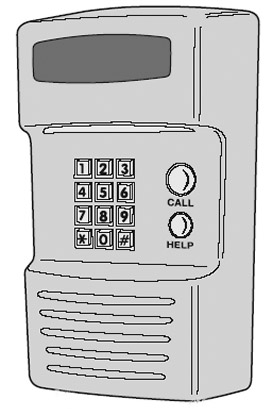
Figure 27-15: A doorway telephone intercom unit - PLC intercomsThese types of intercoms communicate over AC electrical lines and operate in a similar fashion to HomePNA intercoms. However, PLC intercoms can cause potential problems with other PLC systems, such as lighting controls and PLC-based computer networks. For this reason, this type of intercom system isn’t recommended if other PLC systems are in use.
- Wireless intercomsWireless independent intercom systems are essentially room-to-room systems, such as baby monitors and tabletop or wall-mounted units. These units use ultra high frequency (UHF) or very high frequency (VHF) radio frequency (RF) signaling and work on the same principles as a walkie-talkie. Some wireless intercoms also offer the capability to encrypt transmission to prevent exterior interception. Keep in mind that many intercoms advertised as “wireless” are, in fact, PLC systems.
- Stand-alone intercomsStand-alone intercoms are self-contained systems that communicate over their own dedicated wiring. These types of systems have been, and still are, somewhat popular in homes. In addition to allowing a home’s occupants to communicate room-to-room, they can also include doorway units and master unit options that can include a radio receiver and a tape or a CD player that plays music throughout the intercom system stations. Figure 27-16 shows a fully featured stand-alone intercom master unit.
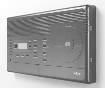
Figure 27-16: A stand-alone intercom master unit with a CD player
- HomePNA intercomsThese types of independent intercoms communicate through a home’s existing telephone wires and the users speak through standard telephone handsets. The intercom action is started by pressing a certain sequence of keys or the number of a special station number on a standard telephone. These systems, like the doorway system shown in Figure 27-15, allow a person arriving at a home’s doorway to place a telephone call into the home and ring the phones with a unique ring. This provides both security and convenience to homeowners.
Photo courtesy of Broan-Nutone.
| Note |
Some homeowners prefer to use standard telephones throughout their home and install a stand-alone intercom system. |
- Telephone-based intercomsUsing the existing or standard telephone wiring and standard phones in a home, a doorbell intercom unit, like the one shown in Figure 27-17, can be installed to enable the doorbell unit to ring a unique ring throughout the home on standard telephones and provide intercom service between the door and the telephones.
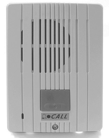
Figure 27-17: A door intercom that connects into a home’s telephone system
Photo courtesy of LocalPlex.
Review
The design process for residential telephone systems includes telecommunication wiring schemes, outlet boxes, wire termination, jacks, punchdown blocks, patch panels, wire identification and labeling, and telephone key sets. Telephone wiring is installed using either series wiring or star/home run wiring, but star/home run wiring is preferred.
The telephone wiring inside a home is the responsibility of the homeowner. It is important to use only category verified wiring that meets or exceeds industry, fire, electrical, and materials specifications and standards, and local building codes. Current industry standards specify a minimum of UTP Cat 3 wiring. However, most new construction installs Cat 5e wiring.
There are four basic elements to a home telephone system: structured wiring, outlet jacks, punchdown or distribution blocks, and phone devices. Wiring installed by the telephone company can include 25-pair cable, satin cord, or four-conductor station wire.
Structured wiring support for a telephone system must address standard phone outlet wiring, structured wiring cable, punchdown/distribution blocks, and connections to the demarc.
Modular jacks are common in most existing homes. This type of jack is surface mounted and provides connection for up to two communication lines on a single jack. Flush-mounted wall outlet jacks are more common in newer homes.
A KSU-based telephone system has its own separate controller that provides many of the same Telco subscriber services to the telephones in the home. The features provided by a residential KSU system include the capability to connect to standard telephones, voice-messaging (voicemail), station-to-station intercom support, auto-attendant, music-on-hold, caller ID, and, in many cases, support for a door intercom. A KSU telephone system is preprogrammed with its basic functions. To add additional phones or features, some adjustments may be required to the KSU’s programming. Prior to beginning any programming or station configuration changes, you should summarize the system’s features on a worksheet that documents the number of telephones to be installed and the features available to each telephone. A worksheet should be used to record the KSU system’s features desired by the homeowners.
There are three basic types of intercom systems: independent intercoms, stand-alone, and telephone-based intercoms. The most common types of independent intercoms are: HomePNA intercoms, PLC intercoms, and wireless intercoms. Stand-alone intercoms are self-contained systems that communicate over dedicated wiring. Telephone-based intercoms allow for intercom service between the doorbell and the house telephones.
Questions
- Under a structured wiring approach, telephone systems should be installed using what wiring scheme?
- Series
- Bus
- Ring
- Star
- What device is placed at the center of the structured wiring for a telephone system?
- RJ-11 outlet
- Distribution panel
- Demarc
- Telephone key set
- Virtually all household wiring standards require the use of what type of wiring?
- Cat 3
- UL Category verified
- Riser
- Plenum
- A type of telephone system that is implemented on a central control unit that supports standard telephones or proprietary phones is a/an:
- Intercom
- KSU
- Telco
- Wireless
- Which of the following is not a type of intercom system?
- Stand-alone
- Independent
- Telephone-based
- KSU
- Which of the following should be done before making any programming changes to a KSU system? (There may be more than one answer.)
- Complete features worksheet
- Interview homeowners
- Program telephone
- Remove default programming
- What cable is typically used to connect a telephone key set to a wall outlet?
- Station wire
- Coaxial cable
- Satin cord
- Zip wire
- Which of the following is not a type of outlet jack commonly associated with telephone connections?
- F-type
- Modular
- Face plate
- Inline
- What do the terms Tip and Ring refer to?
- Incoming signal and bell
- Positive and negative
- Ring and busy tones
- Dial and busy tones
- How many phone lines can be supported by a single run of Cat 3 or Cat 5 cable?
- Two
- Three
- Four
- Six
Answers
- D. Structured wiring is installed using a star topology. The other choices listed can be used for data networks, but aren’t recommended for residential wiring.
- B. The other choices listed should be configured as satellites from the distribution panel.
- B. Category verified cable has been tested and certified to meet residential cable standards. The other choices listed represent residential cable types or characteristics.
- B. A KSU is a central controller device that supports the functions of the telephone units connected to it.
- D. A KSU is a type of telephone system. The other choices are all types of intercoms.
- A and B. Prior to making any programming changes to a KSU, you should interview the homeowners and record their desires on a KSU system worksheet that includes the features of the master unit and each of the telephones.
- C. This flexible pre-configured wire is the common standard for outlet-to-station connections. Station wire, if used, is used for horizontal cabling; coaxial cable is rarely used in voice applications (although it could be); and zip wire is absolutely not voice system wiring.
- A. F-type connectors are associated with coaxial cabling. Inline, though not mentioned in the chapter, is used to connect two RJ-11 connectors together.
- B. At one time, these terms may have had other purposes, but today they represent only positive and negative voltage.
- C. A four-pair UTP cable is able to support as many as four phone lines.
Part I - Home Technology Installation Basics
- Wire and Cable Basics
- Connector Types and Uses
- Wiring Installation Practices
- Codes, Standards, and Safety Practices
Part II - Structured Wiring
- Infrastructure Wiring Basics
- Planning a Structured Wiring Installation
- Rough-In Installation
- Trim-Out Installation
- Troubleshooting Structured Wiring
Part III - Home Computer Networks
- Computer Network Basics
- Computer Network Hardware
- Computer Network Software
- Designing and Installing a Computer Network
- Troubleshooting a Home Network
Part IV - Audio/Video Systems
- Distributed Audio System Basics
- Designing and Installing Distributed Audio Systems
- Distributed Video Basics
- Designing and Installing Distributed Video Systems
- Troubleshooting Audio Systems
- Troubleshooting Video Systems
Part V. Home Lighting Management Systems
- Home Lighting Basics
- Home Lighting Devices
- Designing a Home Lighting Control System
- Installing a Home Lighting Control System
- Troubleshooting and Maintaining Lighting Control Systems
Part VI - Telecommunications
- Home Communication System Basics
- Designing and Installing a Home Telephone System
- Troubleshooting a Home Communication System
Part VII - HVAC and Water Management
Part VIII - Security System Basics
- Security System Basics
- Designing a Home Security System
- Installing a Home Security System
- Troubleshooting and Maintaining a Home Security System
- Home Security Surveillance Systems
- Home Access Control Systems
Part IX - Home Technology Integration
- Defining Users Needs and Desires
- User Interfaces
- Home Automation Controllers
- Programming
- Integrating the Connected Home
- Other Home Technology Integration Devices
Part X - Appendices
EAN: N/A
Pages: 300
