Understanding RAID
|
|
RAID stands for redundant array of inexpensive disks. It doesn't stand for redundant array of independent disks; it's amazing how quickly one wrong source gets duplicated on the Internet, though the term independent has some accuracy. The original term comes from a paper written in 1987 by researchers David Patterson, Garth Gibson, and Randy Katz. It improves performance and fault tolerance. The alternative is often described as single large expensive disk (SLED).
There are a number of different kinds of RAID, described in the following sections. All of them are built upon three basic concepts: mirroring (repeating writes on another drive), striping (dispersing data over multiple drives), and parity (examining bits to prevent and recover from errors).
RAID 0
RAID 0 (sometimes just called striping, as it's not really a true type of RAID) is where data is broken into blocks and spread across multiple drives. Block sizes are the same for each drive, but different block sizes can be set initially depending on the circumstances. This allows for increased performance, as one of the major bottlenecks is moving the drive head. RAID 0 improves the chances of data requested at the same time being on different drives, meaning the read can take place at the same time without having to wait for the one to finish, reposition the head, and then read the second set of data. In general, the more drives there are, the better the performance. Performance is even better if each drive has its own controller, though this is not critical. Just make sure the controllers can handle the load if it is responsible for multiple drives. RAID 0 allows for no fault tolerance, however. In fact, it increases the chance of a failure, as there is more than one drive that can fail, rendering the set of data unavailable.
RAID 0 should not be used in environments where data availability is critical. You need at least two drives to implement RAID 0. It is not a true type of RAID and is sometimes humorously referred to as AID because it contains no form of redundancy (the R in RAID).
In Figure 16.1, which shows RAID 0 implemented on three devices, the first block of data is written on device A, the second on device B, and the third on device C. The next block will then be written on the first device again, and so on. The first and third blocks of data can then be read at the same time, as they exist on different devices.
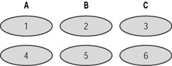
Figure 16.1: RAID 0
RAID 1
RAID 1 (also called mirroring) is where writes to one drive are repeated on another drive. This improves fault tolerance because there is an up-to-date backup in case of one drive failing. Drive failures are the most common type of hardware failure, and RAID 1 protects against this kind of failure. Write performance is poor, as there are simultaneous writes taking place, although reads are slightly quicker, as there are multiple drives to access. You need at least two drives to implement RAID 1.
Figure 16.2 shows RAID 1 being implemented with two drives, each containing an identical copy.
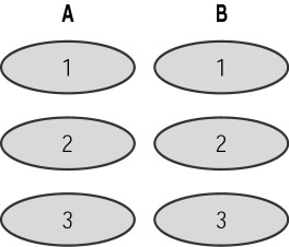
Figure 16.2: RAID 1
RAID 2 and RAID 3
RAID 2 is a rarely used version that makes use of Hamming error correction codes (which uses 3 bits of a 7-bit word for error checking and correction) and is mainly useful for drives that do not do any form of error-protection (SCSI drives do).
RAID 3 is the same as RAID 0, except that it also sets aside a dedicated drive for error correction, providing some level of fault tolerance. Data is striped at a byte level across multiple drives. Another drive stores parity data. Parity is determined during a write and checked during a read. Parity information allows recovery if one drive fails. You need at least three drives to implement RAID 3. It usually requires hardware implementation to be of much use. Small writes and reads are fast, but large blocks of data usually require data to be read from all data drives, meaning that performance can be as slow as a single drive.
Figure 16.3 shows RAID 3 being used to stripe data across two drives (A and B), with a third drive (C) being used to store parity.
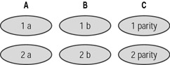
Figure 16.3: RAID 3
RAID 4
RAID 4 is similar to RAID 3, except that striping is performed at block level, not byte level. Reads smaller than one block in size will be fast (generally getting faster as each new drive is added). As with RAID 3, it requires at least three drives, and the parity data allows recovery if one drive fails. The parity drive can become a bottleneck, and choosing RAID 5 can overcome this limitation.
Figure 16.4 shows RAID 4 being used to stripe data across three drives (A, B, and C), with a fourth drive (D) being used to store parity.
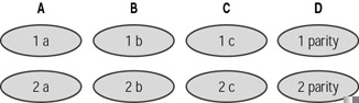
Figure 16.4: RAID 4
RAID 5
RAID 5 also allows for striping, as well as stripe error correction data, improving both performance and fault tolerance. It is similar to RAID 4, except that parity data is stored on each drive. Writes are faster than RAID 4 (there is no one drive bottleneck), but reads are slower, as parity information takes up space on each drive and has to be skipped over. RAID 5 is often recommended for database servers, as it builds in redundancy and improves performance.
A minimum of three drives is required to implement RAID 5.
Figure 16.5 shows RAID 5 being used to stripe data across three drives (A, B, C), each of which contain parity data.
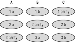
Figure 16.5: RAID 5
RAID 10
RAID 10 is a combination of RAID 1 and RAID 0 (mirroring and striping). It provides all the performance benefits of striping, as well as the fault tolerance of mirroring. It's the best of both worlds, but the cost is high. It requires at least four drives to implement.
Figure 16.6 shows RAID 10 being implemented across four drives (A, B, C, and D). A and B mirror the data (blocks one to four of data appear on both drives), and drives C and D provide the performance boost with data being striped across them. RAID 10 is often suggested for database servers, as it gives the greatest level of performance boost and fault tolerance, albeit at a cost penalty (for the number of drives).
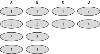
Figure 16.6: RAID 10
RAID 0+1
RAID 0+1 is often confused with RAID 10. Where RAID 10 is a striped array of drives, whose segments are mirrored, RAID 0+1 is a mirrored array of drives, whose segments are striped. Generally RAID 0+1 is chosen when performance is a higher priority than reliability, and RAID 10 is chosen when reliability is a higher priority than performance. RAID 0+1 is also expensive and requires at least four drives to implement. Figure 16.7 shows RAID 0+1 being implemented across four drives (A, B, C, and D).
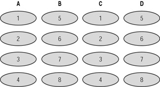
Figure 16.7: RAID 0+1
Other Types of RAID
The previous RAID types are not all the possible types; there are others, some of little practical use.
You can implement RAID using either hardware or software (hardware RAID and software RAID), or a combination of the two. MySQL's --with-raid-option is a limited form of software RAID (RAID 0 currently). Its primary purpose is to overcome the limitation on file sizes. Later versions will extend its usefulness. Replication, although not strictly speaking RAID, is another MySQL software feature similar to RAID (RAID 1). Hardware RAID is usually easier to use because once it's up and running, the hardware device presents multiple drives as one drive to the software and takes care of all redundancy and striping, leaving MySQL to continue as usual. Software RAID makes use of software (for example, vinum, a tool that runs on FreeBSD and implements RAID 0, RAID 1, and RAID 5), which in consequence draws upon the central processing unit (CPU). If you have a CPU with free cycles, software RAID can be as good.
|
|