6.2 Video source coding algorithm
6.2 Video source coding algorithm
The video coding algorithm is shown in Figure 6.3, and is similar to the generic interframe coder of Figure 3.18 in Chapter 3. The main elements are prediction including motion compensation, transform coding, quantisation, VLC and rate control.
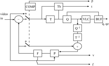
Figure 6.3: A block diagram of H.261 video encoder
The prediction error (inter mode) or the input picture (intra mode) is subdivided into 16 × 16 macroblock pixels, which may or may not be transmitted. Macroblocks that are to be transmitted are divided into 8 × 8 pixel blocks, which are transform coded (DCT), quantised and VLC coded for transmission. As we discussed in section 6.1, the atomic coding unit in all standard video codecs is a macroblock. Hence in describing the codec we will explain how each macroblock is coded.
In Figure 6.3, the function of each coding element and the messages carried by each flag are:
| COMP | a comprator for deciding the inter/intra coding mode for an MB |
| Th | threshold, to extend the quantisation range |
| T | transform coding blocks of 8 × 8 pixels |
| T-1 | inverse transform |
| Q | quantisation of DCT coefficients |
| Q-1 | inverse quantisation |
| P | picture memory with motion compensated variable delay |
| F | loop filter |
| P | flag for inter/intra |
| t | flag for transmitted or not |
| q | quantisation index for transform coefficients |
| qz | quantiser indication |
| V | motion vector information |
| f | switching on/off of the loop filter |
6.2.1 Prediction
The prediction is interpicture, which may include motion compensation, since motion compensation in H.261 is optional. The decoder accepts one motion vector per macro-block. Both horizontal and vertical components of these motion vectors have integer values not exceeding ±15 pixels/frame. Motion estimation is only based on the luminance pixels and the vector is used for motion compensation of all four luminance blocks in the macroblock. Halving the component values of the macroblock motion vector and truncating them towards zero derives the motion vector for each of the two chrominance blocks. Motion vectors are restricted such that all pixels referenced by them are within the coded picture area.
For the transmission of motion vectors, their differences are variable length coded. The differential technique is based on one-dimensional prediction, that is the difference between the successive motion vectors in a row of GOBs. For the first macroblock in the GOB, the initial vector is set to zero.
6.2.2 MC/NO_MC decision
Not all the macroblocks in a picture are motion compensated. The decision whether a macroblock should be motion compensated or not depends on whether motion compensated prediction can substantially reduce the prediction error. Figure 6.4 shows the region (shaded) where motion compensation is preferred. In this Figure the absolute values of frame difference, fd, and those of motion compensated frame difference, mfd, normalised to 16 × 16 = 256 pixels inside the macroblock are compared.
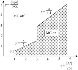
Figure 6.4: Characteristics of MC/NO_MC
From the Figure we see that if motion compensated error is slightly, but not significantly, less than the nonmotion compensated error, we prefer to use nonmotion compensation. This is because motion compensation entails a motion vector overhead (even if it might be zero); hence, if the difference between MC and NO_MC error cannot justify the extra bits, there is no advantage in using motion compensation.
6.2.3 Inter/intra decision
Sometimes it might be advantageous to intraframe code a macroblock, rather than interframe coding it. There are at least two reasons for intraframe coding:
-
Scene cuts or, in the event of violent motion, interframe prediction error, may not be less than that of the intraframe. Hence intraframe pictures might be coded at lower bit rates.
-
Intraframe coded pictures have a better error resilience to channel errors. Note that, in interframe coding, at the decoder the received data is added to the previous frame to reconstruct the coded picture. In the event of channel error, the error propagates into the subsequent frames. If that part of the picture is not updated, the error can persist for a long time.
Similar to the MC/NO_MC decision, one can make a similar decision for coding a macroblock in inter or intra mode. In this case the variance of intraframe MB is compared with the variance of inter (motion compensated or not). The smallest is chosen. Figure 6.5 shows the characteristics of the function for inter/intra decision. Here for large variances no preference between the two modes is given, but for smaller variances interframe is preferred. The reason is that, in intra mode, the DC coefficients of the blocks have to be quantised with a quantiser without a dead zone and with eight-bit resolutions. This increases the bit rate compared with that of the interframe mode, and hence interframe is preferred.
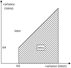
Figure 6.5: Characteristics of inter/intra
6.2.4 Forced updating
As mentioned, intraframe coded MB increases the resilience of the H.261 codec to channel errors. In case in the inter/intra macroblock decision no intra mode is chosen, some of the macroblocks in a frame are forced to be intra coded. The specification recommends that a macroblock should be updated at least once every 132 frames. This means that for common intermediate format (CIF) pictures with 396 macroblocks per frame, on average three MBs of every frame are intraframe coded. This has an important impact on the quality of pictures due to errors. For example, in CIF pictures at 10 Hz, the effect of channel errors may corrupt up to 132 frames, and be visible for almost 13 s.
EAN: 2147483647
Pages: 148
- Chapter I e-Search: A Conceptual Framework of Online Consumer Behavior
- Chapter VIII Personalization Systems and Their Deployment as Web Site Interface Design Decisions
- Chapter X Converting Browsers to Buyers: Key Considerations in Designing Business-to-Consumer Web Sites
- Chapter XI User Satisfaction with Web Portals: An Empirical Study
- Chapter XII Web Design and E-Commerce