6.5 Design Structures
6.5 Design Structures
Every algorithm can be described with four logic structures, and these can be used as basic building blocks in small and in very large and complex algorithms. When using the structures in a disciplined manner, the algorithm described in the pseudo-code is called a structured algorithm, and the design process is sometimes called structured design.
Using simple design concepts with pseudo-code and flowcharts, an algorithm can be built using the following basic design structures:
-
Sequence, which essentially means a sequential ordering of execution for the blocks of instructions
-
Selection, also called alternation or conditional branch; the algorithm must select one of the alternate paths to follow
-
Repetition, also called loops, which is a set (or block) of instructions that are executed zero, one, or more times
-
Input-output, which means the values of indicated variables are taken from an input device (keyword) or the values of the variables (results) are written to an output device (screen)
| Note | All problem solutions include some or all of these structures, each appearing one or more times. To design problem solutions (algorithms) and programs, it is necessary to learn how to use these structures in flowcharts and in pseudo-code. |
6.5.1 Sequence
Figure 6.3 illustrates the first structure, a simple sequence of three blocks of instructions. This is the most common and basic structure. The problem for calculating the area of a triangle is solved using only the sequence and input-output structures. The simple salary problem, which is discussed at the end of this chapter, also uses only these structures.
6.5.2 Selection
Figure 6.4 illustrates the selection structure. In this case, one of two alternate paths will be followed based on the evaluation of the condition. The instructions in Block1 are executed when the condition is true. The instructions in Block2 are executed when the condition is false.

Figure 6.4: Flowchart segment that shows alternate flow of execution for the instructions in Block1 and Block2.
An example of a condition is x > 10. A variation of the selection structure is shown in Figure 6.5. If the condition is false, no instructions are executed, so the flow of control continues normally.

Figure 6.5: Flowchart segment with a selection structure.
The case construct has multiple alternate paths, each one depends on the value of a variable. Figure 6.6 illustrates this construct.
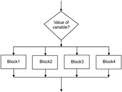
Figure 6.6: Flowchart segment with multiple paths.
6.5.3 Repetition
Figure 6.7 shows the repetition structure. The execution of the instructions in Block1 is repeated while the condition is true.

Figure 6.7: A flowchart segment that shows a structure for repeating the instructions in Block1.
Another form for this structure is shown in Figure 6.8. The instructions in Block1 are repeated until the condition becomes true.

Figure 6.8: Flowchart segment that shows another structure for repeating the instructions in Block1.
EAN: 2147483647
Pages: 184