Installing the Router


Before installing the router, prepare the site as described in "Preparing for Installation" on page 96, and unpack the router as close to the installation site as possible, as described in "Unpacking the Router" on page 103.

Tools and parts required for installation include a mechanical lift (recommended for the T640 routing node and T320, M160, M40, and M20 routers; required for a T640 routing node in an upper rack position), Phillips screwdrivers ( numbers 1 and 2), flat- blade screwdrivers (3/16-inch and 1/4-inch), 9/16-inch socket wrench, 7/16-inch open -end or socket wrench (if the router is being front-mounted), wire cutters, pliers, electrostatic discharge wrist strap, electrostatic bags for components being removed, and an antistatic mat located on a flat, stable surface.

All routers can be installed into a center-mount, front-mount, or four-post rack or a cabinet. The holes in the mounting ears are spaced at 5.25 and at 7 inches (for a T640 routing node, only at 5.25 inches). The rack must be large enough to hold the router and strong enough to support the combined weight of all installed equipment.

Installing the Chassis into a Rack Using a Lift

Because of their large size and weight, Juniper Networks strongly recommends using a lift to install the router. M5 and M10 routers, because of their smaller size and weight, can be installed manually. Before installing the router, make sure that the rack is properly secured to the building in its permanent location and that there is sufficient space around the rack for proper airflow and for servicing the router.

For detailed instructions about installing the mounting hardware for each router, see the Juniper Networks hardware guide for that router.

Some routers come with installation handles, a mounting shelf, or other mounting hardware used to secure the router in the rack. Install the mounting hardware onto the rack, and attach the installation handle to the router, before proceeding to install the router.

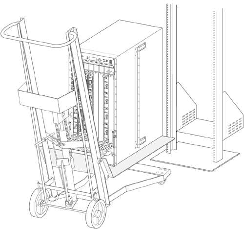
To install a router using a lift (see Figure 4.4):
  1. Load the router securely onto the lift.

  2. Use the lift to position the router in the rack at the correct height.

  3. Align the bottom mounting holes on the chassis mounting ears with the holes in the rack.

  4. Install a mounting screw (provided) into each of the two aligned holes.

  5. Moving up the sides of the router, install screws in every open hole on the mounting ears.

  6. Move the lift away from the rack.

Figure 4.4. Installing a T640 Routing Node Using a Lift

graphics/04fig04.gif

Manually Installing the Chassis into a Rack

Before manually installing a router, remove components from the chassis so that the router is light enough to lift (for the weight of each router, see Table 4.1). Table 4.7 lists the components that must be removed from each router before installing it in the rack.

For detailed instructions about removing router components, see the Juniper Networks hardware guide for that router.

When removing router components, slide each component evenly out of the chassis so that it does not become stuck or damaged. Label each component so that it can be reinstalled in the correct location, and immediately store each removed component in an electrostatic bag or place it on an antistatic mat. Do not stack removed components; lay each one on a flat surface.

After the components are removed, the router chassis can be installed in the rack. Table 4.8 lists the number of people required to lift each router into the rack.

Table 4.7. Components Removed for Manual Installation
  T640 T320 M160 and M40e M40 M20 M5/M10
Front of chassis

FPCs

Front fan trays

Cable manager

FPCs

Front fan trays

Cable manager

FPCs

Fan tray

Upper impeller assembly

FPCs

SCB

Cable manager

Air filter

Impeller tray

FPCs

SSB

Fan trays

No components need to be removed
Rear of chassis

SCGs

CBs

SIBs

Power supplies

SCGs

CBs

SIBs

Power supplies

Impeller assemblies

Routing Engines

MCSs

SFMs

Power supplies

Impeller tray

Routing Engine

Fan tray

Power supplies

Routing Engine

Fan tray

Power supplies

 
Table 4.8. Number of People Required for Manual Installation
  T640 T320 M160 and M40e M40 M20 M5 and M10
People required to install 4 3 3 2 2 2
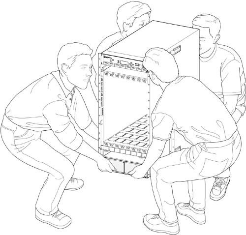
To lift the chassis into the rack (see Figure 4.5):

The installation process for T-series platforms is more complex than for the M-series routers. For more information, see the T640 Internet Routing Node Hardware Guide or the T320 Internet Router Hardware Guide .

  1. Make sure that the shelf or other mounting hardware is installed in the proper position. If the router includes an installation handle, make sure that it is securely attached to the router.

  2. Align the bottom mounting holes on the chassis mounting ears with the holes in the rack.

  3. Install one of the provided mounting screws into each of the two aligned holes.

  4. Moving up the sides of the router, install screws in every open hole on the mounting ears.

Figure 4.5. Installing a Chassis Manually

graphics/04fig05.gif

After installing the chassis in the rack, reinstall the removed components into the chassis. When reinstalling components, slide them evenly into the chassis so that they do not become stuck or damaged.

Some routers (including the T640 routing node and the M160 and M40e routers) include a cover that covers some or all of the rear components. Make sure that the rear component cover is installed and that all empty slots are covered with a blank panel before booting and operating the router.

Connecting Management Consoles and PIC Cables

After the components are reinstalled into the chassis, the router can be connected to an external management device, and the PICs can be connected to the network.

To connect a management console:
  1. Turn off the power switch on the console.

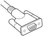
  2. Plug the female end of the RS-232 serial connector into the Console port (see Figure 4.6). On some routers, this port is located on the craft interface. On some routers, it is on the CIP.

    Figure 4.6. Console and Auxiliary Port Connector

    graphics/04fig06.gif

  3. Tighten the screws on the connector.

WARNING

Do not look directly into the PIC transceivers or into the ends of fiber-optic cables. Fiber- optic cables contain laser light sources that can damage your eyes.


To connect the router to a network for out-of- band management:
  1. Plug one of the Ethernet cable connectors into the Ethernet port (see Figure 4.7). On some routers, this port is located on the craft interface. On some routers, it is on the CIP.

    Figure 4.7. Ethernet Port Connector

    graphics/04fig07.gif

  2. Plug the other end into the networking device.

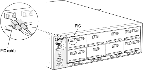
To connect the PIC cables (see Figure 4.8):
  1. Identify the appropriate cable to be connected to each PIC.

  2. Insert the appropriate cable connector into the PIC cable receptacle.

  3. Drape the cables over the bobbins of the cable management system to protect them from bending past their recommended bend radius.

Figure 4.8. Fiber-Optic Cable Connector

graphics/04fig08.gif

Connecting Power and Ground

When the management devices and PIC cables are connected, connect the power and grounding cables. The M40e, M40, M20, M10, and M5 routers can use either AC or DC power; the T640 routing node, T320 router, and M160 router operate using only DC power. The procedures for connecting AC-powered and DC- powered routers are different.

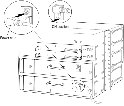
To connect AC-powered routers (see Figure 4.9):
  1. Locate the AC power cable and verify that the cable is the correct type for the site.

  2. Plug the AC power cable into the receptacle on the AC power supply.

  3. Plug the other end of the power cable into the AC power source receptacle.

  4. If the router has two power supplies, repeat Steps 1 through 3 for the second power supply.

Figure 4.9. Connect the AC Power Cord to an M20 Router

graphics/04fig09.gif

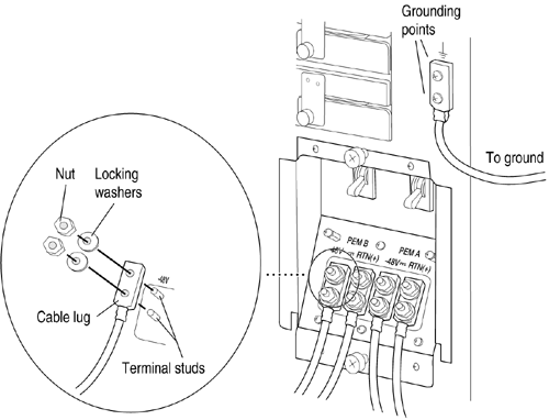
To connect DC-powered routers always connect the router to ground before connecting it to the power source. The terminals for the DC power cables on the T640 routing node, T320, M40, M20, M10, and M5 routers are located on the power supply faceplates. On the M160 and M40e routers, the terminals are located on the circuit breaker box on the lower right of the chassis.

To connect DC-powered routers (see Figure 4.10):
  1. Make sure that the voltage across the DC power source cables is 0 V and that the cable leads will not become active during installation.

  2. Place the grounding cable lug over the grounding points on the chassis. The grounding cable should already be attached to a proper earth ground for both DC power sources.

  3. Secure the grounding cable lug to the grounding points with the washers , then with the bolts.

  4. Remove the clear plastic cover from the power supply faceplate or circuit breaker box.

  5. Attach the power cable lugs for both DC power sources to the terminal studs:

    • Connect the positive (+) cable lugs to the RTN (return) terminals.

    • Connect the negative () cable lugs to the 48V (input) terminals.

  6. Secure the power cable lugs to the terminal studs with the washers, then with the bolts. Verify that the power cabling and the grounding cabling are correct.

  7. Replace the clear plastic cover.

Figure 4.10. Connect DC Power to an M40e or M160 Router

graphics/04fig10.gif

Initial Powerup

After the router is connected to power and ground, power up the router and initially configure the software.

To power up the router:
  1. Make sure that the power supplies are securely installed into the router and that all power and ground cables are properly connected.

  2. Turn on the power to the management device connected to the router through either the console or Ethernet management port.

  3. Turn on one of the power supplies (on an M160 or M40e router, the circuit breakers) and observe the LEDs on the power supply faceplate. The LEDs startup sequence varies for each router.

  4. Turn on the second power supply (or circuit breaker) and observe the LEDs on the faceplate.

  5. On the management device, monitor the startup process to verify that the router has booted properly.


Juniper Networks Field Guide and Reference
ISBN: 0321122445
EAN: 2147483647
Year: 2002
Pages: 185

flylib.com © 2008-2017.
If you may any questions please contact us: flylib@qtcs.net