Traffic Control in MPLS Networks
|
| < Day Day Up > |
|
In networking, MPLS is express traffic that carries four additional bytes of payload. For taking the effort to carry that extra data, it gets to travel the “express lanes.” But, as is too often the case with the actual freeway, the nice, smooth-running express lane that you’ve earned the right to use is subjected to the presence of rerouted routine traffic, thereby bringing you the congestion and slowdowns that you’ve worked to avoid.
Remember that MPLS is an overlay protocol that applies MPLS traffic to a routine IP network. The self-healing properties of IP may cause congestion on your express lanes. There is no accounting for the unforeseen traffic accidents and reroutes of routine traffic onto the express lanes. The Internet is self-healing, with resource capabilities, but the question that arises is this: How do users ensure that the paths and bandwidth reserved for their packets do not get overrun by rerouted traffic?
In Figure 3.2, we see a standard MPLS network with three different paths across the wide area network (WAN). Path A is engineered to the 90th percentile of bandwidth of peak busy hour; Path B is engineered to the 100th percentile bandwidth of peak busy hour; finally, Path C is engineered to the 120th percentile of peak busy hour. In theory, Path A will never have to contend with congestion, owing to sound network design (including traffic engineering). In other words, the road is engineered to take more traffic than it will receive during rush hour. The C network, however, will experience traffic jams during rush hour, because it is designed not to handle peak traffic conditions.
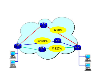
Figure 3.2: MPLS with Three Paths
The QoS in Path C will have some level of unpredictability regarding both jitter and dropped packets, whereas the traffic on Path A should have consistent QoS measurements.
In Figure 3.3, we see a network failure in Path C, and the traffic is rerouted (see Figure 3.4) onto an available path (Path A). Under these conditions, Path A is subjected to a loss of QoS criteria. To attain real QoS, there must be a method for controlling both traffic on the paths and the percentage of traffic that is allowed onto every engineered path.
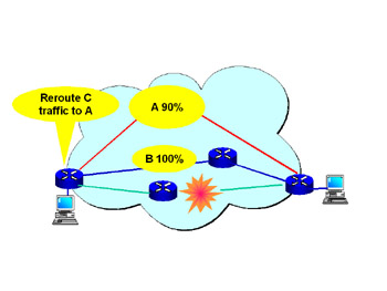
Figure 3.3: MPLS with a Failed Path C
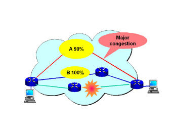
Figure 3.4: MPLS with Congestion Caused by a Reroute
To help overcome the problems of rerouting congestion, the Internet Engineering Task Force (IETF) and related working groups have looked at several possible solutions. This problem had to be addressed both in protocols and in the software systems built into the routers.
In order to have full QoS, a system must be able to mark, classify, and police traffic. In previous chapters, we have seen how MPLS can classify and mark packets with labels, but the policing function has been missing. Routing and label distribution establish the LSPs but still do not police traffic and control the load factors on each link.
New software engines (see Figure 3.5), which add management modules between the routing functions and the path selector, allow for the policing and management of bandwidth. These functions, along with the addition of two protocols, allow for traffic policing.
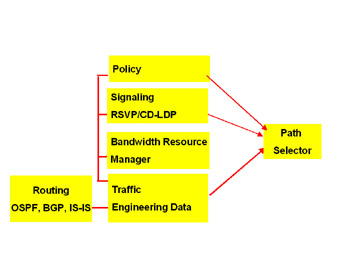
Figure 3.5: MPLS Routing State Machines
The two protocols that give MPLS the ability to police traffic and control loads are RSVP-TE and CR-LDP.
RSVP-TE
The concept of a call setup process, wherein resources are reserved before calls are established, goes back to the signaling theory days of telephony. This concept was adapted to data networking when QoS became an issue.
In 1997 the IETF designed an early method, called Resource Reservation Protocol (RSVP), for this very function. The protocol was designed to request required bandwidth and traffic conditions on a defined or explained path. If bandwidth was available under the stated conditions, the link would be established.
The link was established with three types of traffic that were similar to first-class, second-class, and standby air travel; the paths were called, respectively, guaranteed load, controlled load, and best-effort load.
RSVP with features added to accommodate MPLS traffic engineering is called RSVP-TE. The traffic engineering functions allow for the management of MPLS labels or colors.
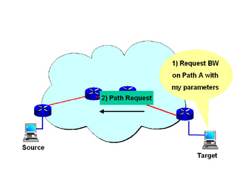
Figure 3.6: RSVP-TE PathRequest
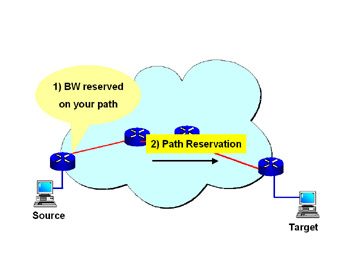
Figure 3.7: RSVP-TE Reservation
This call setup (or “signaling”) process is called soft state because the call will be torn down if it is not refreshed in accordance with the refresh timers. In Figure 3.8, we see that path-request and reservation messages continue for as long as the data is flowing.
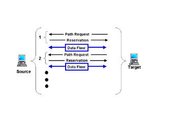
Figure 3.8: RSVP-TE Path Setup
Some early arguments against RSVP included the problem of scalability: The more paths that were established, the more refresh messages that would be created, and the network would soon become overloaded with refresh messages. Methods of addressing this problem include preventing the traffic links and paths from becoming too granular and aggregating paths.
The details of an RSVP-TE path request and reservation can be viewed on the Ethereal.com Web site. In the sample (Figure 3.9), MPLS captures MPLS-TE files. In the capture, we can see the traffic specifications (TSPEC) for the controlled load.
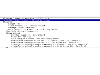
Figure 3.9: RSVP-TE Details
CR-LDP
With Constraint-based Routing over Label Distribution Protocol (CR-LDP), modifications were made to the LDP protocol to allow for traffic specifications. The impetus for this design was the need to use an existing protocol (LDP) and give it traffic engineering capabilities. Nortel Networks made a major effort to launch the CR-LDP protocol.
The CR-LDP protocol adds fields to the LDP protocol. They are called peak, committed, and excess-data rates—terms very similar to those used for ATM networks. The frame format is shown in Figure 3.10.
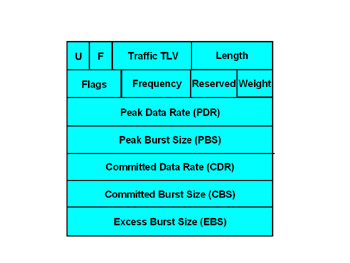
Figure 3.10: CR-LDP Frame Format
The call setup procedure for CR-LDP is a very simple two-step process, involving a request and a map (as shown in Figure 3.11). The reason for the simple setup is that CR-LDP is a hard-state protocol—meaning that, once established, the call, link, or path will not be broken down until a termination is requested.
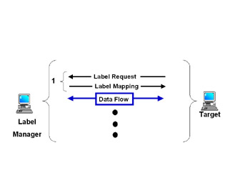
Figure 3.11: CR-LDP Call Setup
The major advantage of a hard-state protocol is that it can and should be more scalable because less “chatter” is required in keeping the link active.
Comparing CR-LDP to RSVP-TE
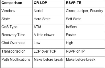
The technical comparisons of the CR-LDP and RSVP-TE protocols are listed in Table 3.1. We see that CR-LDP uses the LDP protocol as its carrier, whereas RSVP-TE uses the RSVP protocol. RSVP is typically paired with IntServ’s detection of QoS, whereas the CR-LDP protocol uses ATM’s traffic engineering terms to map QoS.
Table 3.1: CR-LDP vs. RSVP-TE
| Checkpoint | Answer the following true/false questions.
Answers: 1. False; 2. true; 3. true; 4. false. |
|
| < Day Day Up > |
|
EAN: 2147483647
Pages: 138