6. Case Studies
6. Case Studies
This section describes three common augmented imagery applications that have enjoyed commercial success. In particular, it is useful to identify how the elements of modeling, registration and composition are accomplished in each application.
6.1 Virtual Studios
Evolving from blue-screen composting techniques, virtual studios have been widely used in the film and television industries, replacing traditional sets with computer-generated "virtual" sets, which are integrated seamlessly with live video in real time. Virtual studios are a very basic example of augmented imagery, registering a computer graphics model to matching real-world camera images and compositing the result as a foreground/background image. Virtual studios are distinguished from traditional digital composition in that virtual sets are simultaneously updated according to the movements of real cameras, maintaining correct perspective view angles and spatial positions. Virtual set technologies can be utilized in non-real time applications as well (post-production). This section discusses the real-time virtual studio. To achieve proper registration of the virtual set graphics with the real studio camera images, cameras are tracked so as to acquire position, orientation and lens focal length, allowing for adjustment of the corresponding projection transformation required for image rendering. The registration element of the system is also known as "camera matching," the alignment of the virtual camera in computer graphics environment with the real camera. A system diagram for a virtual studio is shown in Figure 13.12. Although the system architecture is simple, there are many technical challenges to practical implementation, due to the combined requirements of real-time performance and realistic image quality.
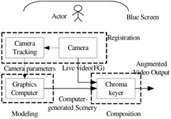
Figure 13.12: Diagram of a virtual studio system
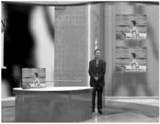
Figure 13.13: An augmented video frame
The first challenge in virtual studios is modeling the generation of virtual environments that will substitute as a real set. A simple approach is to build the graphical scene using 3D modeling software such as Softimage, 3D Studio Max, Maya, etc., in 1:1 scale. But, in practice, many considerations must be taken into account during this task. Graphics hardware cannot render excessively large and complex scenes in real time beyond the hardware's capabilities. Wojdala [46] describes the two main bottlenecks for real-time rendering: the number of polygons and the texture space. It is hard to pose definite limits on these two parameters, because they depend on many factors. But, a number of simplification methods are used to achieve real-time performance, such as replacing flat complex shapes by textures with alpha channels. Another concern is to give the sets realistic looks, such as lighting simulation. Ray tracing or radiosity rendering cannot be used in real-time applications, but can be used to render patches with illuminations and shadows, and map them onto objects in the scene as "faked" lighting effects, adding more credibility to the rendered scene. More discussion on modeling in virtual studio and virtual set design can be found in [47]. Many virtual set applications forego conventional lighting, preferring to precompute lighting and apply it to textures.
Registration in a virtual studio utilizes camera tracking and virtual camera synchronization. The video cameras used in a virtual studio are free to move but must be tracked so that the virtual set can be updated with correct view angles. There are two types of camera tracking methods in common use: pan/tilt/zoom (PTZ) and pattern recognition. In PTZ systems, optical or mechanical encoders are mounted on the tripod or pedestal, which can detect the camera movement relative to a stationary base. If the camera is to be moved around, distance detectors such as infrared or ultrasonic devices are used to measure the camera tripod position. Some commercial tracking systems are now available for this application [48]. Another tracking technology has been developed by Orad Company, which extracts the camera parameters based on the video signal itself. With visible reference points or grid lines in the blue screen, the intrinsic (focus length) and extrinsic (position and orientation) parameters of the camera can be computed using camera calibration algorithms. These two approaches to tracking have advantages or drawbacks, but both of them can provide real-time update of camera spatial information, which can then be used in virtual set rendering.
Composition in virtual studios is generally accomplished using color-based matting or chroma-key. In practice, video compositing is implemented using chroma keyer, a hardware device based on the matting technologies introduced in Section 4. One of the famous keyer manufacturers is Ultimatte. Ultimatte can create seamless composites and preserve fine details such as hair, smoke, mist and shadows.
Virtual studios make it cheaper and easier to produce sets in a computer graphical environment than to build them physically. Continued improvements in rendering quality are narrowing the difference between the real and virtual. Using virtual studios, designers can create scenes previously too difficult, dangerous or expensive. Special effects and animations can be easily imported, adding flexibility to film and television production.
6.2 Virtual First-Down Lines
In the late 1990's, television coverage of professional football games began to include an additional marking on the field indicating the first-down line. The line is added electronically in real-time during the broadcast using technology developed by Sportvision, Inc [49]. Adding virtual elements to the presentation of sporting events was not new at the time. The SailTrack system provided virtual presentations of the race course for the America's Cup yacht races in 1992. The presentation could be expanded or panned to angles not possible with aerial cameras and could provide views of an entire large race course. In the tradition of virtual reality systems, SailTrack provided a virtual representation of the course only. The Sportvision system was the first virtual technology to directly augment live broadcast video.
The process of providing a virtual first-down line is complicated by several factors. The video content is sourced by live cameras in real-time. The cameras can pan, tilt and zoom. The first-down line moves throughout the game, and can be anywhere within the bounds of the field. The line must appear to be a physical part of the field. It must not "swim around," but rather appear to be solidly fixed even as the camera moves. The line must also appear on the field, but not on occluding content such as regular field markings, players or equipment.
Figure 13.14 is a simplified block diagram of the virtual first-down system [49]. Cameras provide the video source in the system. Each camera is equipped with pan/tilt/zoom instrumentation (PTZ), sensors that determine the current orientation and zoom characteristics of the camera. These sensors are typically implemented using mechanical attachments to shaft encoders. A shaft encoder measures rotation in discrete steps, typically providing 40,000 steps for each revolution in this application.
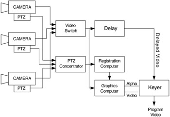
Figure 13.14: Sportvision virtual first-down line system
Augmentation is always applied to the camera currently generating content on-air. A video switch selects the current on-air camera feed. A computer referred to as the PTZ concentrator serves as a switch for PTZ data. The PTZ data is fed to a registration computer, which computes the appropriate transformation for the computer graphics that will allow the virtual elements of the system to register with the real elements. The computed transformation matrix is forwarded to a graphics computer, which renders the virtual first-down line and an alpha map.
The graphics computer provides both the registration transformation and the current camera feed. An additional responsibility of the graphics computer is the computation of an alpha map. Alpha maps are described in Section 4. The alpha map is constructed from the location and blending of the first-down line combined with inclusion/exclusion information derived from the current camera image.
The system utilizes an inclusion/exclusion masking mechanism for computation of alpha maps. The initial map is simply the location of the virtual first-down line and is generated using conventional alpha map techniques in computer graphics systems. An inclusion mask is an image that is white where a first-down line can be placed. The line is always placed on the field, so a chrominance value for the grass or turf is input into the system indicating colors that can be replaced with virtual elements. The input image is scanned for chrominance values in the inclusion range, producing the inclusion mask. The inverse of the inclusion map is subtracted from the initial map, with floor values of zero. Exclusion chrominance ranges can also be defined in the system and are used to construct an exclusion mask. Exclusion ranges are useful for specifying colors that are close to the field color, but are not to be overwritten, such as uniform colors. The exclusion mask is subtracted from the generated mask. Finally, the computed alpha map is filtered to soften any sharp edges. Viewers are less sensitive to registration of soft edges than sharp edges.
The computed graphics image and alpha mask are routed to a keyer, a video composition device that blends inputs based on alpha map values at each pixel. The camera tracking and graphics generation process necessarily introduce several frames of latency into the system. A frame delay ensures the camera feed is delayed by an identical latency period, so that no latency is evident in the result.
Modeling in this application is relatively simple. The only rendered content is the first-down line, which is constrained as perpendicular to the field length. The field is 100 yards long and 50 yards wide. The line is rendered as a 3D line in the graphics system with the virtual camera duplicating the position of the real camera. Because occlusion is handled by the inclusion and exclusion maps, an occlusion model is generally not used.
Registration in this application requires the characterization of the camera system using conventional calibration algorithms [30]. In practice, points are located using poles on the field, laser range finders and a laser plane to determine known x,y,z locations and the corresponding u,v image locations. The transformation necessary for registration is then computed as the composition of the results of the PTZ sensors with the camera calibration. The net effect is that the virtual camera mimics the real, physical camera.
6.3 Virtual Advertising
Virtual advertising is a natural application for augmented imagery. The goal of a virtual advertising system is to add commercial content to existing images in such a seamless way that they appear to have been physically placed in the real environment. The ads may be placed where no advertising previously existed. Examples include placing advertising on the surface of a tennis court or the bottom of a swimming pool. New ads can also replace existing ads. A television broadcaster can sell the same stadium location that the local team has already sold or update advertising in older content. Figure 13.15 is an example of virtual advertising. The existing banner in a stadium has been replaced with a new, virtual banner. Virtual advertising is commonly used to replace the stadium-wall ads behind the batter in baseball games.
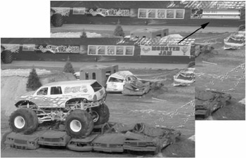
Figure 13.15: Virtual advertising
The development of virtual advertising can be traced to the seminal 1993 patent by Rosser and Leach [50]. They proposed virtual advertising as the placement of a 2D planer image in an existing scene. Later work has added effects such as a ripple to simulate placement in water. A user selects a region of a sample image. The crosshairs in Figure 13.15 illustrate this process. This region is warped to a rectangle of the same pixel dimensions as the substitute image. The warped sample region becomes a template for tracking and alpha map computation.
Rosser and Leach proposed tracking of the location of the original content using pyramidal pattern matching techniques such as the Burt Pyramid Algorithm. Recent systems have supplemented this vision-based tracking with pan/tilt/zoom camera tracking. The sensor-based tracking allows the location of the patch region to be roughly tracked and improves the performance of the matching algorithm. In either case, a matching algorithm provides for sub-pixel resolution determination of the region boundaries as four region corner points. The matching algorithm must be robust to partial occlusion of the region. A batter may step in front of an ad, particularly corners of the ad, at any time.
Figure 13.16 illustrates the process of computing an alpha map. This is an application of difference mattes as described in Section 4. The template region was captured during the system initialization process. The captured and registered image is the warping of a matching region from a captured frame. The difference between these two images is computed as:
| (13.23) |
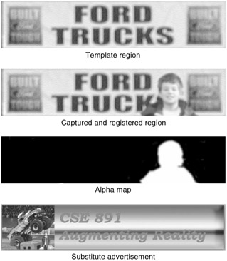
Figure 13.16: Example of computation of an alpha map
In this equation, t and c are the template and captured image frames. An offset a2 is subtracted from the absolute value of the difference so as to decrease noise due to small local differences. The result is multiplied by a factor a1 and then bounded to the range [0,1]. Where the difference is large, the image is likely occluded and the alpha map instructs the keyer to pass the occluding content rather than replacing the advertisement. For all other pixels within the boundaries of the recognized ad, the substitute advertisement replaces the pixel. Some simple refinements have been suggested for this process including low-pass filtering of the difference image to decrease noise and low-pass filtering of the alpha image to smooth edges and better blend the edges into the scene.
Closely related to virtual advertising is virtual product placement, the addition or replacement of products in video sequences. Virtual product placement is allowing motion pictures to defer marking of product placement in film until after production and sell supplemental contracts for television appearances. Virtual product placement requires the 3D registration of the replacement product with the original video sequence and typically cannot count on tracking data availability. Vision-based tracking techniques are used after an initial manual placement.
EAN: 2147483647
Pages: 393