13.3 Protocol Stack
13.3 Protocol Stack
The five layers of the Bluetooth core protocol are divided into two logical parts (Figure 13.3). The lower three layers (Radio, Baseband, and LMP) comprise the Bluetooth module, whereas the upper layers (L2CAP and SDP) make up the host. The interface between these two logical groupings is called the Host Controller Interface (HCI). Note that the HCI is itself a distinct layer of the Bluetooth protocol stack. The reason for separating the layers into two groups stems from implementation issues. In many Bluetooth systems the lower layers reside on separate hardware than the upper layers of the protocol. A good example of this is a Bluetooth-based wireless LAN card. Because the PC to which the LAN card connects typically has enough spare resources to implement the upper layers in software, the LAN card itself only contains the lower layers, thus reducing hardware complexity and user cost. In such a scenario the HCI provides a well-defined, standard interface between the host (the PC) and the Bluetooth module (the LAN card).
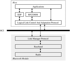
Figure 13.3: Bluetooth protocol stack.
13.3.1 The Radio Layer
Bluetooth devices operate in the 2.4-GHz ISM band. In North America, Europe, and most of the rest of the world, a bandwidth of 83.5 MHz is available in the ISM band. In France, however, the ISM band is much narrower. The Bluetooth SIG has actively lobbied the French regulatory bodies to release the full ISM band; France is expected to comply by 2003. Although the Bluetooth specification defines a separate RF specification for the narrower (French) band, we will not consider it here.
The ISM band is littered with millions of RF emitters ranging from random noise generators, such as sodium vapor street lamps, to well-defined, short-range applications, such as remote entry devices for automobiles. Microwave ovens are particularly noisy and cause significant interference. Clearly, the ISM band is not a very reliable medium. Bluetooth overcomes the hurdles presented by the polluted environment of the ISM band by employing techniques that ensure the robustness of transmitted data. Specifically, Bluetooth makes use of frequency hopping (along with fairly short data packets) and adaptive power control techniques in order to ensure the integrity of transmitted data.
The Bluetooth Radio specification defines a frequency hopping spread spectrum radio transceiver operating over multiple RF channels. The specification divides the 83.5-MHz bandwidth available in the ISM band into 79 RF channels of 1 MHz each, a 2-MHz lower guard band, and a 3.5-MHz upper guard band. The channel frequencies are defined as
2402 + k MHz
where k = 0, 1, ..., 78.
In order to maximize the available channel bandwidth, the data rate for the RF channels is set at 1 Mbps. Gaussian frequency shift keying (GFSK) is used as the modulation scheme, with a binary 1 defined as a positive frequency deviation from the carrier frequency and a binary 0 defined as a negative frequency deviation.
In addition to specifying the modulation scheme, the Radio specification defines also three power classes (Table 13.1) for Bluetooth devices. Each power class has associated with it a nominal transmission range and a maximum power output. The nominal power output for all three classes is 1 mW (0 dBm).
| Power Class | Range of Transmission (meters) | Maximum Power Output (mW/dBm) |
|---|---|---|
| 1 | 3 | 1/0 |
| 2 | 10 | 2.5/4 |
| 3 | 100 | 100/20 |
13.3.2 The Baseband Layer
The baseband layer is by far the most-complex layer defined in the Bluetooth specification. It encompasses a wide range of topics, not all of which can be discussed in this short introduction to the Bluetooth technology. What follows is a brief overview of the key aspects of the baseband layer.
13.3.2.1 Device Addressing
The radio transceiver on each Bluetooth device is assigned a unique 48-bit Bluetooth device address (BD_ADDR) at the time of manufacture. Portions of this address are used to generate three types of access codes: the device access code (DAC), the channel access code (CAC), and the inquiry access code (IAC). The DAC and the IAC are used for paging and inquiry procedures. The CAC is specified for the entire piconet and is derived from the device address of the master device. It is used as the preamble of all packets exchanged on that piconet.
With regard to slave devices on a piconet, there are two other addresses of interest. The first is the active member address (AM_ADDR). This is a 3-bit address that is assigned to an active slave device on the piconet. Because the piconet may have seven active slaves at any given time, a slave's AM_ADDR uniquely identifies it within its piconet. The second address of interest is the parked member address (PM_ADDR). This is an 8-bit address assigned to slave devices that are parked, i.e., devices that are not active on the piconet but remain synchronized to the piconet's master. An active slave device loses its AM_ADDR as soon as it is parked. Similarly, a parked device that becomes active immediately relinquishes its PM_ADDR and takes on an AM_ADDR. Note that the reactivated device may or may not be assigned the same AM_ADDR that it was assigned before it was parked.
13.3.2.2 Frequency Hopping
In order to ensure secure and robust data transmission, Bluetooth technology utilizes a frequency hopping spread spectrum technique. Under this scheme, Bluetooth devices in a piconet hop from one RF channel to another in a pseudorandom sequence. Typically, a hop occurs once at the beginning of every time slot. Because each time slot has a 625-μs duration, the nominal hopping frequency is 1600 hops per second. All devices that are part of the same piconet hop in synchrony. The hopping sequence is based on the master's BD_ADDR and consequently is unique for each piconet.
Because there can be multiple piconets operating in close proximity to each other, it is important to minimize collisions between the devices in different piconets. The specification addresses this issue in two ways. First, the pseudorandom hop selection algorithm is designed to generate the maximum distance between adjacent hop channels. Second, the duration of the time slots is kept very small (625 μs). Time slots of such short duration ensure that even if a collision occurs it will not last long. A collision is unlikely to recur during the next time slot because the piconet will have hopped to a different RF channel.
Strictly speaking, the baseband specification defines a different hopping sequence for different types of operations. The earlier description is that of the channel hopping sequence, which utilizes all 79 RF channels and defines a unique physical channel for the piconet. However, the other hopping sequences (associated with device discovery procedures such as paging and inquiry) utilize only 32 RF channels.
One final note: It was previously stated that the nominal hop rate is 1600 hops per second. This is true only for packets (discussed later) that occupy a single time slot. For packets that occupy three (or five) time slots, the same RF channel is used for transmission during all three (or five) time slots.
13.3.2.3 Link Types (ACL and SCO)
The baseband specification defines two types of links between Bluetooth devices.
-
Synchronous Connection Oriented (SCO) link: This is a bidirectional (64 kbps each way), point-to-point link between a master and a single slave device. The master maintains the SCO link by using reserved time slots at regular intervals. The slots are reserved as consecutive pairs: one for transmissions from the master to the slave and the other for transmissions in the opposite direction. The master can support up to three SCO links simultaneously. A slave device can support up to three simultaneous SCO links with one master or — if it is the adjoining device on a scatternet — it can support up to two simultaneous SCO links with two different masters. SCO links are used for exchanging time-bound user information (e.g., voice). Packets sent on these links are never retransmitted.
-
Asynchronous Connectionless (ACL) link: This is a point-to-multipoint link between the master and all the slaves on a piconet. An ACL link can utilize any packet that is not reserved for an SCO link. The master can exchange packets with any slave on the piconet on a per-slot basis, including slaves with which it has an established SCO link. Only one ACL link can exist between any master-slave pair. ACL links are used for the exchange of control information and user data, therefore packet retransmission is applied to ACL packets received in error.
13.3.2.4 Packet Definitions
The baseband layer defines the format and structure of the various packet types used in the Bluetooth system. The length of a packet can range from 68 bits (shortened access code) to a maximum of 3071 bits. A typical packet (Figure 13.4), however, consists of a 72-bit access code, a 54-bit packet header, and a variable length (0 to 2745 bits) payload.
![]()
Figure 13.4: Packet structure of a typical Bluetooth packet.
Every packet must begin with an access code (see Section 3.2.1). The access code is used for synchronization and identification at either the device level (DAC/IAC) or the piconet level (CAC).
The packet header contains link control information, so it is important to ensure its integrity. This is accomplished by applying a 1/3-rate FEC scheme to the entire header. The packet header consists of six different fields:
-
AM_ADDR (3-bit field): This field contains the active member address of the slave device that transmitted the packet (or, if the master sent the packet, the AM_ADDR of the slave device to which the packet was addressed).
-
TYPE (4-bit field) : This field identifies the type of packet, as explained later in this section.
-
FLOW (1-bit field): This field is used for providing flow control information on an ACL link. A value of 0 (STOP) indicates a request to the sender to stop sending information, whereas a value of 1 (GO) indicates that the receiver is once again ready to receive additional packets. If no packet is received from the receiver, a GO is implicitly assumed.
-
ARQ (1-bit field): This field is used for acknowledging payload data accompanied by a CRC (cyclic redundancy check). If the payload was received without error, a positive acknowledgment (ACK) is sent; otherwise, a negative acknowledgment (NACK) is sent. An ACK corresponds to a binary 1 and a NACK corresponds to a binary 0. Note that NACK is the default value for this field and is implicitly assumed.
-
SEQN (1-bit field): This field is used for a very simple sequential numbering scheme for transmitted packets. The SEQN bit is inverted for each new transmitted packet containing a payload accompanied by a CRC. This field is required for filtering out retransmissions at the destination.
-
HEC (8-bit field) : This field, the header error check, is used for ascertaining the integrity of the header. If the header is received in error, the entire packet is ignored.
The payload portion of the packet is used to carry either voice or data information. Typically, packets transmitted on SCO links carry voice information - with the exception of the DV packet type, which carries both voice and data - and packets transmitted on ACL links carry data. For packets carrying voice information, the payload length is fixed at 240 bits (except DV packets). Packets carrying data, on the other hand, have variable length payloads that are segmented into three parts: a payload header, payload body, and a CRC.
The payload header is either one or two bytes long. It specifies the logical channel on which the payload is to be carried, provides flow control information for the specified channel, and indicates the length of the payload body. The only difference between the one-byte and two-byte headers is that the two-byte headers use more bits to specify the length of the payload body. The payload body simply contains the user host data and the 16-bit CRC field is used for performing error checking on the payload body.
13.3.2.4.1 Packet Types
The packets defined for use in the Bluetooth system (Table 13.2) are identified by the 4-bit TYPE field in the packet header. As is evident from the length of the TYPE field, 16 possible packet types can be defined altogether. Bluetooth packet types can be categorized in four broad groups: control packets, single-slot packets, three-slot packets, and five-slot packets. Single-slot packets require only one time slot for complete transmission. Similarly, three-slot and five-slot packets require three and five time slots, respectively, for complete transmission. The single-slot, three-slot, and five-slot packets are defined differently for the two different link types (SCO and ACL), while the control packets are common to both links.
| Packet Group | Type Code | Packet Name on SCO Link | Packet Name on ACL Link | Number of Slots |
|---|---|---|---|---|
| 0000 | NULL | NULL | 1 | |
| Control group | 0001 | POLL | POLL | 1 |
| 0010 | FHS | FHS | 1 | |
| 0011 | DM1 | DM1 | 1 | |
| 0100 | Undefined | DH1 | 1 | |
| 0101 | HV1 | Undefined | 1 | |
| Single-slot group | 0110 | HV2 | Undefined | 1 |
| 0111 | HV3 | Undefined | 1 | |
| 1000 | DV | Undefined | 1 | |
| 1001 | Undefined | AUX1 | 1 | |
| 1010 | Undefined | DM3 | 3 | |
| Three-slot group | 1011 | Undefined | DH3 | 3 |
| 1100 | Undefined | Undefined | 3 | |
| 1101 | Undefined | Undefined | 3 | |
| Five-slot group | 1110 | Undefined | DM5 | 5 |
| 1111 | Undefined | DH5 | 5 |
The four control packets defined in the specification are:
-
NULL: This packet type is used to return acknowledgments and flow control information to the source.
-
POLL: This packet is used by the master to poll slave devices in a piconet. Slave devices must respond to this packet even if they have no information to send.
-
FHS: The frequency hop selection packet is used to identify the frequency hop sequence before a piconet is established or when an existing piconet changes to a new piconet as a result of a master-slave role switch. This control packet contains the BD_ADDR and clock of the sender (recall that the master's device address and clock are used to generate a pseudorandom frequency hop sequence). In addition, the packet contains also the AM_ADDR to be assigned to the recipient along with other information required in establishing a piconet.
-
DM1: The DM1 (data-medium rate) packet is used for supporting control information on any link. This is necessary, for example, when synchronous information (on an SCO link) must be interrupted in order to supply control information. In an ACL link, this packet can be used to carry user data. The packet's payload can contain up to 18 bytes of information. The payload data is followed by a 16-bit CRC. Both the data and the CRC are encoded with a 2/3-rate forward error correction (FEC) scheme.
The remaining 12 packet types are defined differently for each link. Some packet types have not yet been defined or have been set aside for future use.
13.3.2.4.2 SCO Packets
All packets defined specifically for the SCO link are single-slot packets. They all have a 240-bit payload and do not include a CRC. The first three SCO packets are designed to carry high-quality voice (HV) information (64 kbps) and are defined as follows:
-
HV1: This packet contains 10 bytes of data and is protected by 1/3-rate FEC. Because one packet can carry about 1.25 ms of speech, HV1 packets need to be transmitted once every two time slots.
-
HV2: This packet contains 20 bytes of data and is protected by 2/3-rate FEC. Because one packet can carry about 2.5 ms of speech, HV2 packets only need to be transmitted once every four time slots.
-
HV3: This packet contains 30 bytes of data and is not encoded with an error correction scheme. Because one packet can carry about 3.75 ms of speech, HV3 packets need to be transmitted only once every six time slots.
The last packet type defined for the SCO link is the DV (combined data and voice) packet. This packet contains a 10-byte voice field and a data field containing up to 10 bytes of data. The data field is encoded with 2/3-rate FEC and is protected by a 16-bit CRC. It is interesting to note that the voice and data information contained in this packet are treated completely differently. The voice information - which is synchronous - is never retransmitted, whereas the data information is retransmitted if it is found to be in error. So, for example, if the data field of a packet is received in error, the packet is retransmitted (i.e., the data field contains the same information), but the voice field contains new (different) information.
13.3.2.4.3 ACL Packets
Six different packet types have been defined specifically for the ACL link. All the ACL packets are designed to carry data information and are distinguished from one another by two basic criteria: (1) whether they are encoded with a FEC scheme, and (2) how many time slots they require for complete transmission. The packet types protected with an FEC scheme are referred to as medium data rate (DM) packets, whereas the unprotected packets are referred to as high data rate (DH) packets.
There are two DM packet types defined: DM3 and DM5. Both these packet types are similar to the DM1 control packet in that they are protected with a 2/3-rate FEC scheme. The difference is that unlike DM1, which requires one time slot for complete transmission, DM3 and DM5 require three time slots and five time slots, respectively. Additionally, as one might expect, DM5 packets can carry more data than DM3 packets, which in turn can carry more data than DM1.
Three different DH packet types are defined for the ACL link: DH1, DH3 and DH5. All these packets can carry more data than their DM counterparts because the DH packets are not encoded with an error correction scheme. As with the DM packet types, DH3 and DH5 carry more information than DH1.
The sixth packet type defined for the ACL link is the AUX1 (auxiliary) packet type. This packet type is very similar to DH1 except it does not contain a CRC code.
The remaining packet types have not been defined as yet and have been set aside to accommodate packet types that may be required in the future.
13.3.2.5 Logical Channels
Bluetooth specification defines five logical channels for carrying either link control and management information or user data.
The two channels that carry link control information are the link control (LC) channel and the link manager (LM) channel. The LC logical channel is mapped to the header of every packet (except the ID packet) exchanged on a Bluetooth link. This channel carries low level link information such as flow control, ARQ, etc. The LM channel is typically carried on protected DM packets and it can utilize either link type (SCO or ACL). A packet used for the LM channel is identified by an L_CH value of 11 in the packet's header. The LM channel carries LMP traffic and therefore takes priority over user data channels.
Three logical channels are defined for conveying user data: the user asynchronous (UA) channel, the user isochronous (UI) channel, and the user synchronous (US) channel. The UA and UI channels are normally mapped to the payload of packets transmitted over an ACL link, but they can be mapped also to the data field of the DV packet on an SCO link. The US channel carries synchronous user data (e.g., voice communication) and is mapped to the payload field of packets transmitted over an SCO link.
13.3.2.6 Channel Control
Channel control deals with the establishment of a piconet and adding/removing devices to/from a piconet. The specification defines two primary states for a Bluetooth device: standby and connected. The standby state is the default, low-power state. A device is in the connected state when it is a member of a piconet, i.e., when a device is synchronized to the hop sequence of a piconet.
Devices do not transition directly from the standby state to the connected state, and vice versa. In fact, the specification describes several substates that a device must transition through in order to move from one primary state to the other. These substates are associated with inquiry and paging procedures that are required for slave devices to join or leave the piconet. Figure 13.5 depicts the state transitions involved in going from the standby state to the connected state and back. The observant reader will note that there is a direct transition from the connected state back to the standby state. This direct transition occurs only in case of a hard reset. Normally, devices must methodically detach from the piconet, which requires transitioning through different substates.
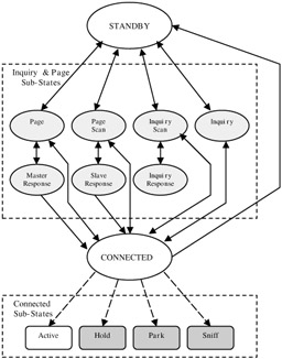
Figure 13.5: State transitions involved in establishing and terminating a Bluetooth link.
The Bluetooth system makes provisions for connected devices to be put into one of three low-power modes while remaining synchronized to the hop sequence of the piconet. These modes (discussed further in Section 3.3) can be considered as substates of the connected state (Figure 13.5).
13.3.2.7 Error Checking and Correction
Bluetooth provides a variety of error checking and error correction mechanisms. Bluetooth packets can be checked for errors at three levels. When a packet is received, the receiver immediately checks its channel access code (recall that the CAC is the preamble for all packets). If the CAC embedded in the packet does not match the CAC of the piconet, then either the packet was received in error, or the packet was destined for another piconet. In either case, the packet is discarded. If the CAC matches the CAC for the piconet, the next error checking mechanism is employed. This involves checking the header error check. If the HEC indicates that the header data has irrecoverable errors, the packet is again discarded. If the packet passes this second error-checking test, the final error checking mechanism involves checking the CRC to check the integrity of the packet payload.
Bluetooth also makes use of three different error correction schemes. The first two schemes are 1/3-rate FEC and 2/3-rate FEC. Using these two schemes, it may be possible to recover from bit errors without having to retransmit the packet. However, if the packet payload cannot be recovered despite the use of these two correction schemes or if no FEC was used, then an ARQ scheme is used to request retransmission of the packet. For more information on either FEC scheme, please refer to the Bluetooth specification. [6]
13.3.2.8 Security
Security is of paramount importance in any wireless (RF) communication. It is even more important in the case of Bluetooth, which aims at becoming a ubiquitous, de facto standard for wireless communications. With this in mind, the specification provides for security mechanisms in more than one layer of the protocol stack. At the baseband (lower link level), the facility for link security between two devices relies on two different procedures:
-
Authentication: Procedure used to verify the identity claimed by a Bluetooth device
-
Encryption: Procedure used to encode user data so that it is unintelligible until decoded using a specific key
The security algorithms defined in the baseband specification utilize the following four parameters:
-
BD_ADDR: Publicly known 48-bit address of the device
-
Authentication key: 128-bit secret key preconfigured with the device
-
Privacy key: Variable length (4 to 128 bits) secret key that is preconfigured also with the device
-
Random number: 128-bit number used for device authentication
In addition to these key responsibilities, the baseband layer addresses other issues, including transmit/receive timing, data whitening, and encoding of audio information for transmission over Bluetooth links.
13.3.3 The LMP Layer
The Link Manager Protocol is responsible for establishing and maintaining ACL and SCO links, and establishing, managing, and terminating the connections between different devices. LMP provides a mechanism for the link managers (LMs) on separate devices to exchange messages containing link management information with each other. These messages are sent as LMP protocol data units (PDUs) and are carried in the payload of single-slot packets (DM1 or DV) transmitted on the LM logical channel.
Because LMP PDUs are used for link management, they have been assigned a very high priority. Consequently, LMP PDUs may be transmitted during slots reserved for an SCO link. The PDU contains three fields:
-
A 1-bit transaction ID field, which specifies whether the link management transaction was initiated by the master (0) or the slave (1) device
-
A 7-bit OpCode field, which identifies the PDU and provides information about the PDUs payload
-
A payload field, which contains the actual information necessary to manage the link
Many PDUs have been defined for the different transactions defined in the specification. Two of the most general response PDUs are LMP_Accepted and LMP_Not_Accepted. Although many link management transactions have been defined in the specification, not all of them are mandatory. However, the LM on every Bluetooth device must be able to recognize and respond to any of the specified transactions. In case the LM on the receiving device does not support a particular transaction, it must still respond to the requesting device's LM with an LMP_Not_Accepted PDU.
In the remainder of this section we will briefly mention some of the more-important link management transactions defined in the specification. These transactions are grouped into three broad categories: link control, power management, and security management.
Link management transactions used for link control include:
-
Connection establishment: Before two devices can exchange L2CAP information, they must first establish a communications link (Figure 13.6). The procedure for establishing a link is as follows: the LM of the device requesting the connection sends an LMP_Host_Connection_Req PDU to the receiving device. The LM of the receiving device may then either accept or reject the request. If the request is accepted, the LMs of the two devices further negotiate the parameters of the link to be set up. When this negotiation is completed, the LMs of both devices send an LMP_Setup_Complete PDU to each other and the link is established.
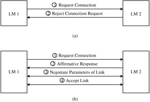
Figure 13.6: LM connection request transactions— In both cases, the transaction is initiated by LM 1 (on device 1). (a) LM 2 rejects the request for establishing a connection, and the transaction terminates; (b) LM 2 accepts the request, LM 1 and LM 2 negotiate the link parameters, the negotiation process is completed, and the connection is established. -
Link detachment: When a device wishes to terminate its link to another device, it issues an LMP_Detach PDU. The receiving device cannot reject the detach request and the link between the two devices is immediately terminated.
-
Clock and timing information: LMP PDUs in clock-and-timing-related transactions are used by devices to obtain clock offsets and slot offsets from each other. Support for many of these PDUs is mandatory because link timing cannot be established or negotiated without them.
-
Master-slave role switch: This transaction plays an important role in the establishment of a scatternet. [7] The device that wants to switch roles initiates the process by sending an LMP_Switch_Req PDU. If the request is accepted, the role switch occurs after the two devices exchange some timing information.
-
Information exchange: Transactions of this type allow devices to request information from each other. As an example, a (local) device may want to inquire another (remote) device about the optional link manager features supported by the receiving device. In that case, the local device sends an LMP_Features_Req PDU to the remote device. In addition to requesting a list of features supported by the remote device, the PDU contains information about the optional features supported by the local device. When the remote device receives the request, it sends an LMP_Features_Res PDU back to the local device. The LMP_Features_Res PDU contains information about the optional features supported by the remote device. At the end of the transaction, both devices are aware of the optional services supported by the other.
Power management transactions allow Bluetooth devices the flexibility to conserve power when they are not actively exchanging information. The transactions in this category include:
-
Sniff mode: While an active slave must monitor every even-numbered time slot for transmissions from the master, a slave device in sniff mode has to monitor far fewer slots. Note that slots reserved for an SCO link are not affected by sniff mode. A master may force a slave device into sniff mode by sending an LMP_Sniff PDU to the slave. Alternatively, either the master or the slave may request that the slave device be placed in sniff mode by issuing an LMP_Sniff_Req PDU.
-
Hold mode: In an established piconet, there may be times when a slave device will not be addressed for a significant duration. In such instances, it is highly desirable to place the slave device in sleep-like mode for the duration of time that it will not be addressed, in order to conserve power. In hold mode, the ACL link between the master and slave is temporarily suspended (i.e., there is no ACL traffic between the master and slave). The duration for which the link is suspended is called the hold time and is stipulated at the time the link is suspended. Note that any SCO links between the master and slave device are unaffected. As with sniff mode, the master may either force a slave into hold mode (LMP_Hold PDU) or either the master or the slave may request that the slave be placed in hold mode (LMP_Hold_Req).
-
Park mode: In the sniff and hold modes, the slave device is considered an active member of the piconet (i.e., it is still one of the seven active slave devices on the piconet). In park mode, however, the slave device is no longer active on the piconet; however, it still remains synchronized to the piconet. The advantage is that if the device needs to rejoin the piconet, it can do so very quickly. Interested readers are referred to the LMP specification for further information.
Security is addressed in more than one layer of the Bluetooth protocol stack. In the LMP layer, the key security management transactions are device authentication and link encryption; while the former is a mandatory feature of all Bluetooth devices, the latter is optional.
-
Device authentication: This transaction is based on a challenge response scheme. The transaction begins by one device (the verifier) sending an LMP_Au_Rand PDU to another device (the claimant). The PDU contains a 128-bit random number. The claimant uses this number as the input to an encryption function. The output of this function is then transmitted back to the verifier. If the value received by the verifier matches the value it expects, the claimant is authenticated. At the end of this transaction, the verifier and claimant may swap roles in order to authenticate the link in the opposite direction. The authentication transaction is far more complex than the simple procedure outlined here. A much more detailed explanation can be found in the Bluetooth LMP specification. [8]
-
Link encryption: Link encryption is often necessary to protect the privacy of the data transmitted over a Bluetooth link. This transaction is initiated when a device issues an LMP_Encryption_Mode_Req PDU. The encryption mode determines whether the encryption is to be applied to a point-to-point link only or to broadcast packets as well. If the request is accepted, the devices negotiate the size of the encryption key to be used by exchanging LMP_Encryption_Key_Size_Req PDUs. Once the encryption key size has been determined, the devices begin the encryption process by issuing an LMP_Start_Encryption PDU.
13.3.4 The L2CAP Layer
The L2CAP layer serves to insulate higher-layer protocols (including non-Bluetooth-specific protocols such as TCP/IP, PPP, etc.) from the lower-layer Bluetooth transport protocols. In addition, it supports protocol multiplexing with respect to higher-layer protocols. Another key feature of the L2CAP layer is that it facilitates segmentation and reassembly of higher-layer packets. Note that L2CAP itself does not segment (or reassemble) packets. It simply provides packet length information to the higher-layer protocols, which allows those protocols to segment (and reassemble) the packets submitted to (and received from) the L2CAP layer. L2CAP supports quality-of-service (QoS) features by allowing the exchange of QoS information between the L2CAP layers on different devices.
The L2CAP layer messages are sent in packets known as L2CAP PDUs. These PDUs are carried on ACL packets transmitted on the user asynchronous logical channel. Because these PDUs may be carried on multislot packets, the L_CH field in the payload header of the ACL packets is used to indicate whether the current packet is the start of the L2CAP PDU (denoted by an L_CH value of 10) or a continuation of the L2CAP PDU (denoted by an L_CH value of 01). The L2CAP layer does not itself guarantee the reliable transmission of L2CAP PDUs. It assumes that the packet retransmission facility provided by the baseband layer is sufficient for ensuring a reliable communication channel.
All communication between the L2CAP layers on different devices occurs over logical links referred to as channels (Figure 13.7). These channels are identified by the two endpoints (one on the first device, the other on the second device) of the link. Each endpoint is assigned a unique 16-bit channel identifier (CID). The CIDs are assigned locally, i.e., the endpoint local to a particular device is assigned its CID by the L2CAP layer of that same device. These endpoints are in turn uniquely associated with some recipient (e.g., higher-layer protocol) to which the payload of the L2CAP PDU is delivered. The CIDs are administered locally and the scheme for assigning CIDs is left up to the implementer. The only exception is that some CIDs have been reserved (Table 13.3) for specific channels.
| CIDhex | Description |
|---|---|
| 0000 | NULL identifier |
| 0001 | Signaling channel |
| 0002 | Connectionless reception channel |
| 0003-003F | Reserved |
| 0040-FFFF | Dynamically allocated |
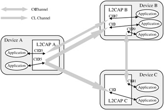
Figure 13.7: L2CAP channels between three different devices. Device A maintains two connectionless (CL) channels, one each with Device B and Device C. Devices A and B share a bidirectional connection-oriented (CO) channel also, as do Device B and Device C. Note that all the channels terminate at endpoints in the L2CAP entities of the different devices. Each of these endpoints is assigned a CID by its L2CAP entity. The endpoints in each of the devices are uniquely associated with some recipient application.
The Bluetooth specification defines three types of L2CAP channels:
-
Connection-oriented (CO) channel: This is a persistent channel that supports bidirectional communication and requires the exchange of signaling information before it can be established.
-
Connectionless (CL) channel: CL channels are unidirectional, are not persistent, and are typically used for broadcast messages. If a device wants to respond to a L2CAP transmission on a CL channel, it must send its response on another channel. Also, CL channels allow the L2CAP layer to provide protocol multiplexing (refer to the specification for additional details).
-
Signaling channel: This is very similar to the CO channel except that its CID (and other channel parameters) are fixed, and therefore no signaling information is exchanged in order to establish the channel. Indeed, the signaling channel is itself used for exchanging signaling information.
13.3.4.1 L2CAP Channel Management
In order for a CO channel to be established or terminated, signaling information has to be exchanged between the local and remote devices. This signaling information is exchanged by means of a request-and-response transaction mechanism. The signaling commands used in this transaction are L2CAP_Connection_Req, L2CAP_Connection_Res, L2CAP_Configuration_Req, L2CAP_Configuration_Res, L2CAP_Disconnection_Req, and L2CAP_Disconnection_Res. There are additional signaling commands defined in the specification, but they will not be discussed here.
The procedure for establishing a CO channel is as follows: the local device (i.e., the device that wants to establish the CO channel) sends an L2CAP_Connection_Req command to the remote device. The command contains the source CID (i.e., the CID of the endpoint on the local device) and other signaling information. If the remote device accepts the connection request, it sends an L2CAP_Connection_Res command back to the local device. The response command contains the destination CID (i.e., the CID of the endpoint on the remote device), as well as other signaling information. Once the CO channel has been established, it has to be configured. The local and remote devices negotiate channel configuration by exchanging L2CAP_Configuration_Req and L2CAP_Configuration_Res commands. If the two devices cannot agree on configuration parameters, the CO channel is either terminated or the default configuration parameters (implementation dependent) are used. The most important of the configuration parameters negotiated between the two devices are the QoS parameters.
13.3.5 The SDP Layer
Bluetooth technology was developed to support mobility and facilitate the formation of ad hoc networks. This scenario is qualitatively different from "static" networks in which member devices do not constantly leave/join the network. In an ad hoc network, devices are free to join or leave the network at whim. This presents a complex challenge, because a device leaving a network may deprive the network of some service that only that device provides. On the other hand, a device that joins a network (piconet) may provide a service that was previously not available on any other device in that network. So how does any device on the network know what services are available on the network at any given time? This is precisely the issue addressed by the SDP.
SDP utilizes the concept of a client/server model. Clients are devices that are searching for services, whereas servers are devices that provide services. These roles are entirely interchangeable, i.e., any device can be either a client or a server, depending on whether it is using a service provided by another device or providing a service to another device. SDP requires that all devices (in their role as servers) maintain a service registry. The service registry is a collection of service records that provide information (service attributes) about the services provided by the device.
SDP specifies two types of service attributes: (1) universal service attributes, which could apply to any class of service (e.g., printing, telephony, LAN access, etc.); and (2) service-specific attributes, which are meaningful only in the context of a particular service class. It is important to note that the universal service attributes are not necessarily mandatory. In fact, the specification mandates only two such attributes: the service class attribute, which identifies the class or type of service, and the service record handle, which is a pointer to the service record of that service. [9]
Service discovery is accomplished by means of SDP transactions. SDP transaction information is communicated using SDP PDUs. In order for service discovery to work, it is necessary that the services are represented in a standard format, one that both the client and the server can use to refer to the service. SDP uses universally unique identifiers (UUIDs) to represent the services. Typically, two transactions are required in order for a client to obtain service information from the server: a service search transaction, and a service attribute transaction. The first transaction is initiated by the client when it sends an SDP_Service_Search_Req PDU to the server. Upon receiving this request, the server responds to the client with an SDP_Service_Search_Res PDU. The response PDU returns a list of service record handles that match the service requested by the client. Of course, if the server does not support the requested service, it still responds to the client, but the list of service record handles is empty. Following the response from the server, the client begins the second transaction by sending an SDP_Service_Attribute_Req PDU to the server. The parameters of this PDU are the service record handle (for the service of interest) and the attribute IDs of the attributes desired by the client. When the server receives the SDP_Service_Attribute_Req PDU from the client, it responds with an SDP_Service_Attribute_Res PDU that contains a list of attributes (attribute ID and the corresponding value) retrieved from the service record specified by the service record handle supplied by the client. At the end of the second transaction, the client should have enough information to connect to the service. It is important to note that SDP does not actually provide the client with the requested service. If the client wants to connect to the service, it utilizes some other protocol to do so.
There is a third type of transaction defined in the SDP specification, but it is simply a composite of the first two transactions, and is not discussed here. Interested readers may refer to the specification itself for additional details.
[6]Specification of the Bluetooth System - Core online, available at http://www.bluetooth.com.
[7]Miller, B.A. and Bisdikian, C., Bluetooth Revealed: The Insider's Guide to an Open Specification for Global Wireless Communications, Prentice-Hall, Upper Saddle River, NJ, 2001.
[8]Specification of the Bluetooth System - Core online, available at http://www.bluetooth.com.
[9]Stallings, W., Wireless Communications and Networks, Prentice-Hall, Upper Saddle River, NJ, 2002.
EAN: 2147483647
Pages: 239