Working with Hatches and Fills
Working withHatches and Fills
Overview
- Selecting a predefined hatch pattern and applying it to a drawing
- Setting up and applying user-defined hatch patterns
- Modifying the scale and shape of a hatch pattern
- Specifying the origin of a hatch pattern
- Filling an enclosed area with a solid color
- Setting up and using palettes and palette tools
Hatches can be abstract patterns of lines, solid fills, or they can resemble the surfaces of various building materials. To give texture to an AutoCAD drawing, a drafter will hatch in areas or fill them in with a solid color. Solid fills in a drawing can give a shaded effect when printed using a half-screen, resulting in a look quite different from the solid appearance in the AutoCAD drawing on the screen.
In an architectural floor plan, the inside of full-height walls are often hatched or filled to distinguish them from low walls. Wooden or tile floors can be hatched to a parquet or tile pattern. In a site plan, hatches are used to distinguish between areas with different ground covers, such as grass, gravel, or concrete. When working with elevations, almost any surface can be hatched to show shading and shadows, and realistic hatch patterns can be used to illustrate the surfaces of concrete, stucco, or shingles. Hatches and fills are widely used in mechanical, landscaping, civil, structural, and architectural details as a tool to aid in clear communication.
To learn how to hatch and fill areas, you will start with some of the visible surfaces in the front elevation of the cabin. You will then move to the floor plan and hatch the floors and put hatch patterns and fills in the walls. You’ll use the Hatch command for all hatching and filling. It is a complex command with many options.
A key part of a hatch pattern is the boundary of the pattern. The area being hatched is defined through a complex procedure in which AutoCAD searches the drawing for lines or objects to serve as the hatch boundary.
Hatching the Front Elevation
Hatches and fills generally need to be on their own layers so they can be turned off without also making other objects invisible. We will begin the exercise by creating new layers for the hatches and assigning colors to them.
- Open the Cabin08a drawing. It should contain the floor plan and front elevation only. Turn off any running Object Snaps and turn off the UCS icon.
Tip To get the best visual effect from putting hatch patterns on the front elevation, change the background color for the drawing area to white. Choose Tools Options to open the Options dialog box and then click the Display tab. Click the Colors button and make the change.
- Set up three new layers as follows:
Layer Name
Color
Hatch-elev-brown
42
Hatch-elev-gray Gray
(8)
Hatch-elev-black Black (White)
(7)
- Make the Hatch-elev-gray layer current. Now any new objects you create will be assigned to this layer.
- Click the Hatch icon on the Draw toolbar to open the Boundary Hatch And Fill dialog box (see Figure 9.1). You will use this dialog box to choose a pattern, set up the pattern’s properties, and determine the method for specifying the boundary of the area to be hatched. The Hatch tab should be active. If it’s not, click the tab. Predefined and ANSI31 should be displayed in the Type and Pattern drop-down lists, respectively. If not, open the lists and select those options.
You can also start the Hatch command by choosing Draw Hatch or by typing h.
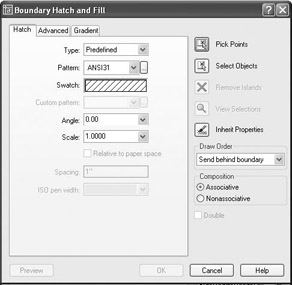
Figure 9.1: The Boundary Hatch And Fill dialog box - Move to the right of the Pattern drop-down list and click the Browse button to open the Hatch Pattern Palette dialog box (see Figure 9.2). Of the four tabs, ANSI will be active, and the ANSI31 pattern will be highlighted.
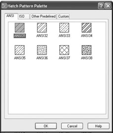
Figure 9.2: The Hatch Pattern Palette dialog box - Click the Other Predefined tab. Find the AR-RROOF pattern, click it, and then click OK. Back in the Boundary Hatch And Fill dialog box, note that AR-RROOF has replaced ANSI31 in the Pattern drop-down list. A new pattern is displayed in the Swatch preview box, which is below the Pattern list (see Figure 9.3).
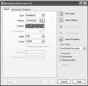
Figure 9.3: The Boundary Hatch dialog box with the AR-RROOF pattern chosenYou can change the Scale and Angle settings in their drop-down lists, which are below the Swatch preview box. In the Angle drop-down list, the preset angle of 0.00 is fine, but you need to adjust the Scale setting.
- In the Scale drop-down list, delete 1.0000 and type 6. The Scale drop-down list contains preset scale factors that range from 0.2500 to 2.0000. To set the scale to 6, you have to type it. Once you do that, however, 6 is added to the drop-down list and is displayed as 6.0000 the next time you open the dialog box.
- Move to the upper-right corner of the dialog box and click the Pick Points button. This returns you to the drawing.
- In the elevation view, click the middle of the roof area. The lines that form the boundary of the roof area ghost, forming an outline of the area to be hatched (see Figure 9.4).
Figure 9.4: The roof’s boundary is selected. - Right-click and choose Preview from the shortcut menu. In the preview drawing, take a look at how the hatch will appear. This hatch looks fine for now.
- Right-click to accept this hatch. The hatch is now placed in the roof area (see Figure 9.5).
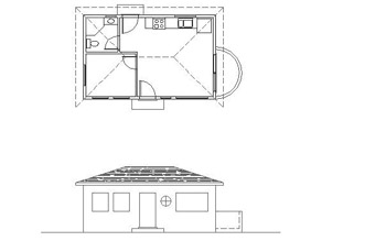
Figure 9.5: The finished hatch pattern in the roof area - Zoom in to a view of just the front elevation. Notice how the appearance of the hatch pattern changes with the new view.
Looking at Hatch Patterns
Let’s take a short tour through the available patterns.
- Start the Hatch command.
- In the Boundary Hatch And Fill dialog box, be sure that the Hatch tab is active. Then click the Browse button that is next to the Pattern drop-down list to open the Hatch Pattern Palette dialog box.
- Make the Other Predefined tab active if it is not already. Look at the display of hatch patterns. Eleven pattern names begin with AR-, including the one just used. These patterns have been designed to look like architectural and building materials; hence, the AR prefix. In addition to the roof pattern we just used, there are several masonry wall patterns, a couple of floor patterns, and one pattern each for concrete, shakes, and sand.
- Scroll down the display and observe the other non-AR patterns. They are geometrical patterns, some of which use conventions to represent various materials.
- Click the ANSI tab, and take a look at a few of the ANSI patterns. These are abstract line patterns developed by the American National Standards Institute and are widely used by public and private design offices in the United States.
- Click the ISO tab. These are also abstract line patterns developed by another organization, the International Organization for Standardization. The Custom tab will be empty unless custom hatch patterns have been loaded into AutoCAD.
- Click Cancel in the Hatch Pattern Palette dialog box. Click Cancel again to close the Boundary Hatch And Fill dialog box.
As you work with hatch patterns, you will need to adjust the scale factor for each pattern so the patterns will look right when the drawing is printed. The AR patterns are drawn to be used with the scale factor set approximately to the default of one-to-one (displayed as 1.0000) and should need only minor adjustment. However, the pattern you just chose for the roof is an AR pattern, and its scale factor needed to be changed to 6.0000. The AR-RROOF pattern is somewhat anomalous compared with the rest of the AR patterns and requires this unusually large adjustment.
| Tip |
When using one of the AR patterns, leave the scale factor at 1.0000 until you preview the hatch; then you can make changes. This rule also applies to the 14 ISO patterns displayed on the ISO tab of the Hatch Pattern Palette dialog box. |
For the rest of the patterns, you will need to assign a scale factor that imitates the true ratio of the scale at which you expect to print the drawing. Table 9.1 gives the true ratios of some of the standard scales used in architecture and construction.
|
Scale |
True Scale Factor |
|---|---|
|
1" = 1'-0" |
12 |
|
" = 1'-0" |
24 |
|
" = 1'-0" |
48 |
|
⅛" = 1'-0" |
96 |
|
1⁄16" = 1'-0" |
192 |
The scale is traditionally written by mixing inches with feet in the expression, which causes some confusion. For example, the third scale in the table, commonly called “quarter-inch scale,” shows that a quarter inch equals one foot. A true ratio of this scale would have to express the relationship using the same units, as in 1⁄4" = 1'-0". Simplifying this expression to have no fractions, you would translate it to, say, 1" = 48". This is how you arrive at the true scale factor of 48, or the true ratio of 1:48.
As you continue through this chapter, take special note of the various scale factors used for different hatch patterns.
Hatching the Rest of the Front Elevation
You will apply hatches to the foundation, front door, and front wall. We’ll then work with some special effects.
Using a Concrete Hatch on the Foundation
For the foundation hatch, keep the Hatch-elev-gray layer current.
- To represent the top of the foundation, draw lines from the upper-left and upper-right corners of the step to the edges of the building (see Figure 9.6a). Activate Osnaps as needed.
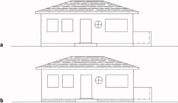
Figure 9.6: The front elevation with foundation lines drawn (a), and the resulting hatches in place (b) - Start the Hatch command. Then click the Browse button next to the Pattern drop-down list in the Boundary Hatch And Fill dialog box.
- Activate the Other Predefined tab. Find and select the AR-CONC pattern and click OK.
- Open the Scale drop-down list and select 1.0000.
- Click Pick Points. Then, in the drawing, click once in each rectangle representing the foundation. The borders of these areas will ghost.
After you click the Pick Points button in the Boundary Hatch And Fill dialog box, pick a point in the area to be hatched. AutoCAD finds the boundary of that area and displays its ghosted form.
- Right-click, and then choose Preview. Then right-click again to accept the hatch. The concrete hatch pattern is applied to the foundation surfaces (see Figure 9.6b).
Hatching the Front Door and Wall
For the front door, we’ll use a standard hatch pattern, ANSI31. This is the default pattern when you first use the Hatch command, but now the default pattern is the last one used.
- Start the Hatch command and click the Browse button.
- Activate the ANSI tab. Select ANSI31 and click OK.
- In the Scale text box, highlight 1.0000 and type 18. Then click Pick Points.
- Click the middle of the door. The edges of the door and door sill ghost.
- Right-click, and then choose Preview. Observe the preview, and then right-click again. The door is hatched (see Figure 9.7).
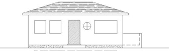
Figure 9.7: Hatching the door - Change the current layer to Hatch-elev-brown.
- Start the Hatch command, and go through the same process to apply a hatch to the wall. This time you will use the AR-RSHKE pattern, which looks like wooden shingles (often called shakes). Here is a summary of the steps:
- Click the Browse button.
- Activate the Other Predefined tab, select the AR-RSHKE pattern, and click OK.
- Set the Scale to 1 and click Pick Points.
- Pick any place on the front wall that’s not inside a window.
- Right-click, choose Preview, and then right-click again.
The wall is hatched (see Figure 9.8).
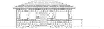
Figure 9.8: The hatching of the front wall is complete.
Using a Solid Fill Hatch
The windows will be hatched with a solid fill. You apply this hatch in the same way as the other hatches you have been using, except that you don’t have a choice of scale or angle.
- Make Hatch-elev-black the current layer.
- Start the Hatch command, and then click the Browse button. Make sure the Other Predefined tab is active, and select the first pattern, SOLID. Click OK. Back in the Boundary Hatch And Fill dialog box, note that the text boxes for Scale and Angle are not available. These don’t apply to solid fills.
- Click Pick Points. In the drawing, select a point in the middle of each of the four windows. You will have to click the round window four times because of the mullions (the separators between the panes).
- Right-click, choose Preview, and then right-click again. The windows have a solid black (or white) fill (see Figure 9.9).
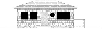
Figure 9.9: The windows with a solid fill hatch
Special Effects
To finish the front elevation, you need to show shading and work a little with a curved surface.
Applying Shading to a Surface
When shaded surfaces are illustrated on an exterior elevation, they give a three-dimensional quality to the surface. We’ll put some additional hatching at the top portion of the wall to illustrate the shading caused by the roof overhang.
You need to hatch the top 2'-6" of the wall with the same hatch that was put on the front door. To determine the boundary line of the hatch, you need to turn off the layer that has the shake pattern. You will then create a guideline to serve as the lower boundary of the hatch.
- Be sure the Hatch-elev-black layer is still current. Then turn off the Hatch-elev-brown layer.
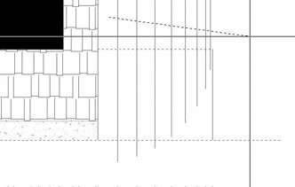
- Offset the soffit line of the roof down 2'-6" (see Figure 9.10a).
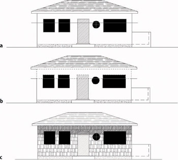
Figure 9.10: Applying a hatch to a shaded area: drawing a guideline (a), finding the hatch boundary (b), and the resulting effect (c) - Start the Hatch command. In the Boundary Hatch And Fill dialog box, click the Inherit Properties button. You are returned to the drawing. The cursor is now a pickbox accompanied by a paintbrush, telling you that AutoCAD is in Select Hatch mode.
- Click the hatch pattern on the door. The Command window displays the name, scale, and rotation of the hatch pattern you picked. Now the prompt is Select internal point:.
- Pick a point on the wall above the offset line but not inside the door or windows. Click the door hatch above the offset line. The boundary lines ghost (see Figure 9.10b). Press .
- In the Boundary Hatch And Fill dialog box, change the scale from 18 to 16. Click the Preview button in the lower-left corner. After a look, right-click. The pattern is applied to the upper part of the wall.
- Turn on the Hatch-elev-brown layer and erase the offset guideline. The drawing will look like Figure 9.10c.
You erased the offset guideline because there is no edge on the wall at the bottom of the shaded area. And you used the Inherit Properties button to set up a hatch pattern exactly like the one already present in the drawing. You can also use the List command on hatch patterns to find out the name, scale, and rotation of an existing pattern, as well as the layer that the hatch is on.
Indicating a Curved Surface
The curved outside wall of the balcony appears as a rectangle in the front elevation. You need to use a pattern that will increase in density in the X direction as we move around the curve. Vertical straight lines will do the job if you space them properly. You’ll use the floor plan to help you to do that.
- Make the Hatch-elev-brown current. Use Realtime Zoom and Zoom Window to arrange a view similar to the one in Figure 9.11.
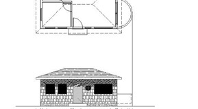
Figure 9.11: A line is dropped from the balcony in the floor plan to the elevation. - Use the Line command with Quadrant Osnap to start a line from the right extremity of the outside balcony wall. Use Endpoint Osnap to end the line at the top-right corner of the balcony in the elevation.
- Turn off the Headers, Roof, and Steps layers. Use Zoom Window to zoom in to the lower half of the balcony in the floor plan. Set Endpoint Osnap to be running, and then use Center Osnap to draw a line from the center point of the balcony arc down to the lower-right corner of the building (see Figure 9.12a).
When using the Center Osnap, place the cursor on the arc or circle whose center you are trying to snap to. The Center Osnap symbol appears at the center of the arc or circle.
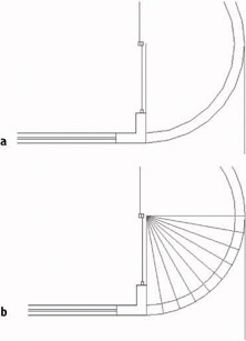
Figure 9.12: The line drawn from the center of the balcony (a), and the results of the Polar array (b)
Here’s the plan. If you create a series of equally spaced radii across the lower-right quadrant of the balcony, vertical lines dropped from these radii will give you a graduated spacing to indicate the curved surface of the balcony wall in elevation. The Polar Array tool helps you do that.
If the arcs seem segmented after zooming in on them, choose View Regen to readjust the screen and make the arcs look like true arcs.
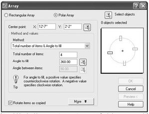
- At the Command: prompt, click the Array button on the Modify toolbar to open the Array dialog box. At the top are two radio buttons. Click the Polar Array radio button.
- In the upper right of the Array dialog box, click the Select Objects button. Select the line that you just drew from the center of the balcony to the corner of the building, and then press .
- Just to the right of the Center Point X and Y coordinate text boxes, click the Pick Center Point button.
- Back in the drawing, select the upper endpoint of the line that you just drew.
- In the Array dialog box, note the Method drop-down list box. It should say Total Number Of Items & Angle To Fill. If it does, move to step 6. If not, open the drop-down list and select that option.
- In the Total Number Of Items text box, enter 10, but don’t press yet.
- In the Angle To Fill text box, enter 90 but don’t press yet.
- In the lower-left corner of the dialog box, make sure a check mark is in the Rotate Items As Copied box. Then click the Preview button. The preview should look like Figure 9.12b. If it does, click the Accept button. The line is arrayed around the lower half of the balcony (see Figure 9.12b).
- Set Endpoint Osnap to running, if it’s not already. Then use grips again to copy/move the dropped line to the endpoint of each line that was just arrayed. Here is a summary of the steps:
- Click the dropped line to activate grips.
- Click the grip on the upper endpoint.
- Right-click and choose Move from the shortcut menu.
- Right-click again and choose Copy. This activates the Copy options for the Move command.
- Click each spoke line (like the spoke of a wheel) on its outer endpoint. Don’t copy the line to the vertical spoke line you first drew.
- Type x, and then press Esc to remove the grips.
The results will look like Figure 9.13a. Now you have all the lines you need to complete the task. To finish, get rid of what you no longer need.
- Erase all the spoke lines and the original dropped line (see Figure 9.13b).
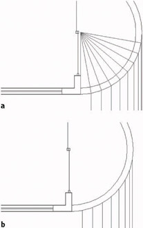
Figure 9.13: The drop line is copied to the ends of the spoke lines (a), and the spoke lines and first dropped line are erased (b). - Turn on the Headers, Roof, and Steps layers. Zoom Previous, and then zoom in close to the elevation of the balcony.
- Erase the two dashed lines that represent the floor and inside wall of the balcony.
- Start the Trim command, and select the line representing the top edge of the balcony wall and the ground line. Press . Type f to activate the Fence selection option.
- Draw a horizontal line that crosses over the eight vertical lines extending above the balcony, and then press . The eight lines are trimmed down to the balcony, and the Trim command is still running.
- Click the three lines that extend below the ground line. Click them below the ground line. Press the Shift key and click the five lines that need to be extended to the ground line. Press to end the Trim command (see Figure 9.14).
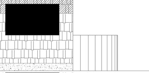
Figure 9.14: The balcony in elevation after erasing, extending, and trimming lines
Modifying a Hatch Pattern
You won’t know for sure if the hatch patterns will look right until you print the drawing, but you can at least see how they look together now that you’ve finished hatching the elevation.
- Zoom Previous, and use Realtime Pan to display both the floor plan and the elevation on the screen (see Figure 9.15a). The roof hatch could be a little denser. You can use the Modify Hatch command to change the hatch scale.
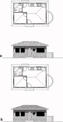
Figure 9.15: Full view of the drawing with the hatching completed for the front elevation (a), and the same view with the roof hatch modified (b) - Double-click the roof’s hatch pattern.
You can modify several kinds of objects by double-clicking them. This activates a dialog box in which you can edit them. I’ll point out this feature along the way.
- In the Hatch Edit dialog box, change the scale from 6.000 to 4.
- Click OK. The roof hatch pattern is denser now (see Figure 9.15b).
- Save this drawing as Cabin09a.
You can use the Modify Hatch command to change the pattern, scale, or angle of an existing hatch.
If you worked on putting more detail in the front elevation in the previous chapter and saved this drawing as Cabin08b, you can go through the exercise again with that drawing. You can then see how more detail and hatch patterns enhance the way the elevations appear. Figure 9.16 shows the front elevation with hatch patterns and more detail in the door and windows. If you have the time to do any hatching on this drawing, save your work as Cabin09b.
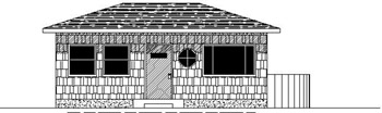
Figure 9.16: Cabin09b with the front elevation hatched
Using Hatches in the Floor Plan
In the floor plan, you can use hatches to fill in the walls or to indicate various kinds of floor surfaces. We’ll start with the floors.
Hatching the Floors
So far you have used only predefined hatch patterns—the 69 patterns that come with AutoCAD. There is also a user-defined pattern, which is a series of parallel lines that you can set at any spacing and angle. If you want to illustrate square floor tile, select the Double option of the user-defined pattern, which uses two sets of parallel lines—one perpendicular to the other, resulting in a tiled effect.
The User-Defined Hatch Pattern
You’ll use the user-defined pattern for a couple of rooms and then return to the predefined patterns.
- With Cabin09a open, zoom in to the floor plan, and be sure the Headers and Doors layers are visible. You can use the header lines to help form a boundary line across an entryway to a room and to keep the hatch pattern from extending to another room.
- With the floor plan in full view, zoom in to the bathroom and freeze the Roof layer. Even if the roof lines are dashed, they will still form a boundary to a hatch.
- Create a new layer called Hatch-plan-floor. Assign it color 142 and make it current. (If you have only 16 colors, choose any color.)
- Start the Hatch command. Be sure the Hatch tab is active.
- Open the Type drop-down list and select User-defined. The list closes, and User-defined replaces Predefined as the current pattern type. The Pattern and Scale drop-down lists are not available, but the Spacing text box is.
- In the Spacing text box, change 1" to 9". Below and to the right of that, click the Double check box to activate it. Then click Pick Points.
- Back in the drawing, be sure no Osnaps are running. Then click a point in the bathroom floor, not touching the fixture lines or the door. Click the floor between the door swing and the door, being careful to not touch the door.
- Right-click, and choose Preview from the shortcut menu. The tiled hatch pattern should fill the bathroom floor and stop at the header, while not going onto the door or fixtures. If the tile pattern looks OK, right-click again (see Figure 9.17).
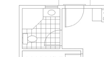
Figure 9.17: The tiled hatch pattern in place
Note that in the user-defined pattern, there is no scale factor to worry about. You simply set the distance between lines in the Spacing text box.
| Warning |
If you can’t get the Hatch command to hatch the desired area, you might not have drawn some of the lines serving as the hatch boundary accurately. This can prevent AutoCAD from being able to find the boundary that you intend to use. Zoom in to the areas where objects meet and check to see that they really do meet where they should. |
Controlling the Origin of the Hatch Pattern
Often a designer will want to lay out the tile pattern such that the pattern is centered in the room. To do this, the tiles are set to start in the center of the room and move out to the edges, where they are cut to fit. We’ll use the Snapbase setting to set this up in the bedroom.
- Use Realtime Pan to slide the drawing up until the bedroom occupies the screen. Use Realtime Zoom to zoom out if you need to.
- Turn Otrack on (on the status bar), and set Midpoint Osnap to be running.
Steps 2 and 3 are for AutoCAD users only. LT users should follow steps 2 and 3 in the following “For LT Users” sidebar.
- Type snapbase. Place the cursor at the midpoint of the inside wall line on the left. A cross (called a tracking point) will appear inside the triangular Midpoint Osnap symbol. Don’t click.
Move to the wall line at the upper part of the room and do the same thing. Then move the cursor straight down until it is positioned directly to the right of the first acquired tracking point. When the cursor is positioned properly, two tracking lines and a tool tip are displayed (see Figure 9.18a). Click. This sets the origin of any subsequently created hatch patterns at the center of the room.
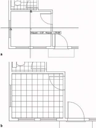
Figure 9.18: Hatching the bedroom: the two tracking lines (a), and the finished, centered hatch (b)
For LT Users
LT users should follow these steps:
- Set Midpoint Osnap to be running.
- Type snapbase. Click the Tracking button at the top of the Object Snap toolbar. Hold the cursor at the midpoint of the inside wall line on the left. When the Midpoint Osnap triangle appears, click.
Move the cursor up to the upper wall line and do the same thing. Then press .This sets the origin of any subsequently created hatch patterns at the center of the room.
- Start the Hatch command. The User-defined pattern type is still current, and the spacing is set to 9".
- Change the spacing to 12". Be sure Double is still checked, and then click Pick Points.
- In the drawing, pick a point anywhere in the middle of the bedroom and between the door swing and the door, similar to what you did in the bathroom. Right-click and choose Preview.
- Inspect the drawing to see if the hatch looks all right, and then right-click again. The hatch of 12" tiles is placed in the bedroom (see Figure 9.18b). Note how the pattern is centered left to right and top to bottom.
The default setting for Snapbase is 0,0, or the origin of the drawing. Each time you change this setting, all subsequent hatch patterns will use the new setting as their origin. For most hatches, the origin isn’t important, but if you need to control the location of tiles or specific points of other hatch patterns, you can reset the Snapbase setting before you create the hatch.
Finishing the Hatches for the Floors
To finish hatching the floors, you’ll use a parquet pattern from the set of predefined patterns in the living room and kitchen and another user-defined pattern on the balcony.
- Use Realtime Pan and Zoom to adjust the view so it includes the living room, kitchen, and balcony.
- Start the Hatch command and set the current pattern type to Predefined.
- Click the Browse button and activate the Other Predefined tab. Select the AR-PARQ1 pattern. Set the scale to 1, and be sure the angle is set to zero. Then click Pick Points.
- Click anywhere in the living room. Then click between each of the door swings and doors for the front and back doors. Check the ghosted boundary line to be sure that it follows the outline of the floor.
- Right-click, and then choose Preview from the menu. The squares look a little small.
- Press Esc to return to the Boundary Hatch And Fill dialog box. Reset the scale to 1.33.
- Click Preview. This looks better. Right-click to accept it. The parquet pattern is placed in the living room and kitchen (see Figure 9.19).
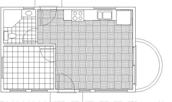
Figure 9.19: The parquet hatch in the living room and kitchen - Type snapbase. The Midpoint Osnap should still be running. Pick the threshold line that extends across the sliding glass door opening near its midpoint.
- Restart the Hatch command, and set User-defined to be the pattern type.
- Clear the Double check box. Set the spacing to 0'6". Click Pick Points.
- Click anywhere on the balcony floor.
- Right-click, and then choose Preview. Right-click again. The balcony floor is hatched with parallel lines that are 6" apart (see Figure 9.20).
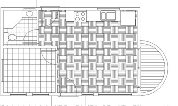
Figure 9.20: The user-defined hatch on the balcony floor
With the floors complete, the only components left to hatch are the walls.
Hatching the Walls in the Floor Plan
A solid fill is often used for full-height walls but not for low walls. The interior and exterior walls of the cabin are all full height and will be hatched with a solid fill. You’ll then use a regular predefined pattern for the low balcony wall.
- Zoom and pan to a full view of the floor plan.
- Create a new layer called Hatch-plan-wall. Assign it the same color that you are using for the Walls layer, and make this new layer current.
- Start the Hatch command. Set the type to Predefined. Open the Pattern drop-down list, and select Solid from the list.
- Click Pick Points. In the drawing, click the 10 areas inside the wall and between the door and window jamb lines.
- Right-click, choose Preview, and look at the drawing. The fill will look a little odd because the blue boundaries of the wall line are ghosted. Check to be sure all 10 areas in the wall are properly filled, and then right-click again. The walls now have a solid fill.
- Restart the Hatch command and click Pattern.
- Select ANSI31 for the pattern, and enter a scale of 24.
- Click Pick Points, and pick a point between the two balcony arcs.
- Right-click, choose Preview, right-click again, and then click OK. A diagonal crosshatch pattern is placed on the balcony wall (see Figure 9.21).
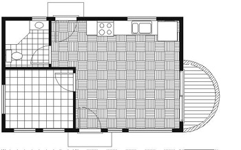
Figure 9.21: The hatched balcony wall
This completes the exercises for setting up and placing hatch patterns.
Modifying the Shape of Hatch Patterns
The next exercise will demonstrate how hatches are associative. An associative hatch pattern automatically updates when you modify the part of a drawing that is serving as the boundary for the pattern. You will be changing the current drawing, so before you begin making those changes, save the drawing as it is.
- Zoom out and pan to get the floor plan and front elevation in the view. Thaw the Roof layer.
- Save this drawing as Cabin09c. You’ll use the Stretch command to modify this drawing.
- Turn off the Hatch-elev-gray layer. Zoom in to the front elevation. Turn Polar Tracking on.
- Click the Stretch button on the Modify toolbar.
- Pick a point above and to the right of the ridge of the roof in elevation. Drag a window down and to the left until a crossing selection window encloses the ridgeline of the roof (see Figure 9.22a). Click to complete the window. Then press to finish the selection process.
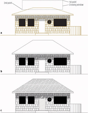
Figure 9.22: The crossing selection window (a), the modified roof (b), and the adjusted hatch pattern (c) - For the base point, choose a point in the blank area to the right of the elevation.
- Hold the cursor directly above the point you picked so that the Polar Tracking line and tool tip appear; then type 3'. The roof is now steeper (see Figure 9.22b).
- Turn on the Hatch-elev-gray layer (see Figure 9.22c). The hatch pattern has expanded to fill the new roof area.
- Zoom Previous. Save this drawing as Cabin09d.
Hatches are a necessary part of many drawings. You have seen a few of the possibilities AutoCAD offers for using them in plans and elevations.
Creating and Managing Tool Palettes
If you find yourself using particular hatch patterns over and over in various drawings, make them available at a moment’s notice instead of setting them up each time. AutoCAD’s tool palettes let you do just that. You looked at this feature briefly in Chapter 7, but now we’ll go through the process of setting up a couple of them and customizing them to contain specific hatch patterns, blocks, and commands that are used with the cabin drawings. From this exercise, you will get the information you need to set up your own custom palettes.
Creating a New Tool Palette
You’ll create a new tool palette and then populate it with the blocks we’ve used so far in the cabin drawing.
- Click the Tool Palettes icon on the Standard toolbar to display palettes on the screen. Then place the cursor on a blank space on the palettes, right-click, and choose New Tool Palette. A new blank palette displays with a small text box on it.
- Type Cabin Blocks to name the new palette.
- Open DesignCenter by clicking the DesignCenter button on the Standard toolbar. If it isn’t already docked, dock it on the left side of the drawing area.
- On the left side of DesignCenter, navigate to the Cabin09c drawing. When you find it, click the + sign to its left. The list of types of drawing content that are available opens below the drawing.
- Select Blocks from this list. Now the right side of DesignCenter displays the three blocks in Cabin09c, either as small images or by name only. Click the arrow on the Views button in the upper-right corner of DesignCenter, and choose List as the view option (see Figure 9.23).
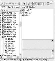
Figure 9.23: DesignCenter with the List view option - Select door2_6, then hold down the Shift key and click win-1 to select all three blocks. Then left-click and drag the three blocks over to the new palette. Small images of the blocks are displayed on the Cabin Blocks palette (see Figure 9.24), and they are now available for any drawing. Simply drag a block off the palette onto the drawing. You can then fine-tune its location, rotate it, and so forth. Any layers used by the block will also be brought into the drawing.
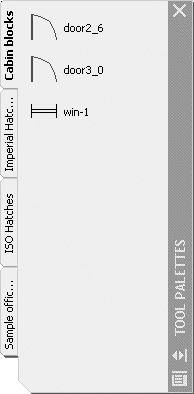
Figure 9.24: The new Cabin Blocks tool palette - Place the cursor on door3_0 on the new palette, right-click, and then select Properties to open the Tool Properties dialog box. It displays information about door3_0 (see Figure 9.25).
- Close the Tool Properties dialog box.
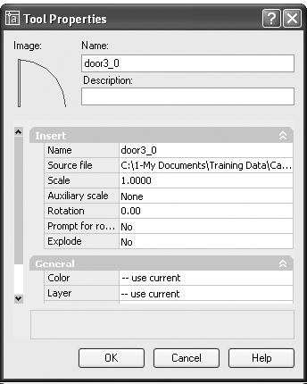
Figure 9.25: The Tool Properties dialog box
Setting Up a Palette for Hatches
To create a palette for hatches, you create and name a new palette using the same procedure as in the previous section, but the hatches get onto the palette in a different way.
- Right-click in a blank space on the Cabin Blocks palette, choose New Tool Palette, and then type Cabin Hatches in the text box.
- Zoom in on the front elevation of the cabin, and click the roof hatch to display a grip.
- Move the cursor to a portion of the roof hatch that is not close to the grip, then left-click and drag the hatch pattern over to the new palette (see Figure 9.26).
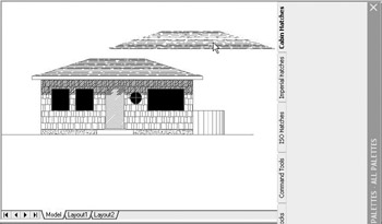
Figure 9.26: Moving the roof hatch to the new palette - When the cursor is over the palette and a horizontal line appears there, release the mouse button. The roof hatch is now positioned on the palette and available for use in any drawing. Simply drag it off the palette and into the enclosed area in your drawing that you desire to hatch with that pattern.
- Place the cursor on the new swatch of AR-RROOF, right-click, and choose Properties. The Tool Properties dialog box opens.
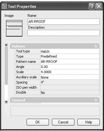
- Change the name from AR-RROOF to Cabin Roof. Enter a description of what the hatch represents, such as Composition Roofing. Notice that the hatch has the angle and scale that were used on the roof and that it’s also on the Hatch-elev-gray layer. Use the slider at the left to view all the properties. Click OK to close the dialog box and update the palette is (see Figure 9.27).
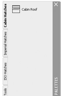
Figure 9.27: The Cabin Hatches palette after being renamed
By using the Properties palette, you can also give hatches color. All the hatches that you’ve used for the cabin so far can be placed on the palette in the same manner. They retain the properties that they had in the original drawing, but by using the Properties dialog box, you can change those properties.
Creating a Palette for Commands
Take a moment to look at some of the sample palettes that come with AutoCAD, and check the properties of some of the items that you see. In addition to blocks and hatches, there are also command icons. These are placed on the palette in a slightly different way from blocks and hatches.
- Right-click the Cabin Hatches palette in a blank area, and choose New Tool Palette from the shortcut menu.
- Name the new palette Commands.
- Right-click the new palette, and choose Customize to open the Customize dialog box. Be sure Commands is the active tab (see Figure 9.28).
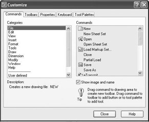
Figure 9.28: The Commands tab in the Customize dialog box - In the list of categories on the left, highlight Draw. Then scroll down the commands list on the right and drag Arc Start Center Angle over to the palette, just as you dragged the hatches in the previous section.
- Drag Circle Center Radius to the palette. Then select the Modify category, scroll down the commands list again, and drag Copy Object and Stretch over to the Commands palette (see Figure 9.29).
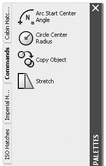
Figure 9.29: The Commands palette with four command iconsWhen you need to use one of these commands, simply click the icon on the palette.
If you set the palettes to Auto-hide, they fold under the palette title bar. When you put your cursor on the bar, the palettes display and then hide a moment after your cursor moves off the palettes. To activate Auto-hide, right-click the palette title bar and choose Auto-hide from the shortcut menu.
This has been a brief introduction to the palette feature. I encourage you to experiment with the various options to become familiar with them, so you can use them as you find the need. Try right-clicking a blank portion of the palette and investigating the commands available on the resulting shortcut menu. You can delete any palette, and you can copy tools from one palette to another.
If You Would Like More Practice
If you would like to practice what you’ve learned in this chapter, here are a couple of extra exercises.
Create a Hatch Pattern for the Roof in Plan View
To create your hatch pattern for the roof, make these changes and additions:
- Make the Roof layer current, and change its linetype from Dashed to Continuous. Turn off all other layers.
- Put a chimney in the roof approximately as shown in Figure 9.30a. Here are the dimensions:
- The rectangle is 2'-8" by 3'-0".
- The circle has an 8" radius. It is centered horizontally, and its lower quadrant point is set 4" up from the lower edge of the rectangle.
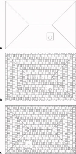
Figure 9.30: The roof with continuous lines and with a chimney (a), the new hatch for the roof (b), and the roof hatch with Island Detection adjusted and chimney moved (c)
- Create a new layer called Hatch-plan-roof. Assign it the same color you are using for the Roof layer. Make this new layer current.
- Apply the AR-RSHKE pattern to each quadrant of the roof, changing the rotation angle by 90 for each adjacent area. Use a scale of 1.0000. When you pick the quadrant with the chimney, pick a point in the quadrant that is outside the chimney rectangle. The result should look like Figure 9.30b.
- Double-click the hatch in the quadrant that contains the chimney. In the Hatch Edit dialog box, click the Advanced tab to make it active. In the Island Detection area, select the Outer option. Click the Hatch tab, and then click OK. Now the hatch pattern does not appear in the circle.
- Move the chimney rectangle and circle to a different location in the quadrant and see the results (see Figure 9.30c). The hatch adjusts. What happens if you move the circle and rectangle that make up the chimney to a different quadrant or to a location completely off the roof? Try it.
Create Your Hatch Palette
It is true that any hatch pattern can be used to represent anything you want it to, but most trades and professions follow some sort of standard, even if loosely. The ANSI31 pattern of parallel lines is probably the most widely used pattern. Though it “officially” represents, according to the ANSI standard, Iron, Brick, and Stone Masonry, it is universally accepted as representing any cross-section view of any material, that is, the part of the object that was actually “sliced” through to make the view.
Create a new palette of hatches that you might use in your work. Use the same method that I demonstrated in the previous section of this chapter:
- Open DesignCenter, and find the acad.pat file in the UserDataCacheSupport subfolder of the AutoCAD 2005 or AutoCAD LT 2005 folder. Open that file.
- Use the Large Icon view to view the patterns on the right side of DesignCenter.
- Scroll through and highlight any patterns you might use by holding down the Ctrl key as you select them. Do include the eight ANSI patterns.
- When finished, right-click and choose Create New Tool Palette from the shortcut menu.
- Close DesignCenter, and name the new palette.
- Hold the cursor briefly over the name of each hatch to display a tool tip that describes the purpose of the hatch.
- If you have brought any patterns to the palette that you don’t want there after all, right-click each of them and choose Delete from the shortcut menu. Don’t worry about changing any of the properties such as scale or rotation. That will come later, as you begin to use these hatches in your own work.
- Check out the tools on the sample palettes: ISO Hatches, Imperial Hatches, and Sample Office Project. Right-click some of the hatches, fills, or blocks, and note how the rotation and scales vary for hatches that look the same on the palette. One hatch, such as ANSI31, might be repeated several times on the same palette, with each occurrence having a different scale or rotation. Note that the names of the hatches and fills have been removed from two of the sample palettes. Can you figure out how to do this or how to store the names?
Are You Experienced?
Now you can
- create a predefined hatch pattern and apply it to a drawing
- set up and apply user-defined hatch patterns
- create a polar array of a line
- use lines to indicate a curved surface
- modify the scale of a hatch pattern
- modify the shape of a hatch pattern
- control the origin of a hatch pattern
- create and populate a tool palette for blocks, hatches, or commands
Introduction
- Getting to Know AutoCAD
- Basic Commands to Get Started
- Setting Up a Drawing
- Gaining Drawing Strategies: Part 1
- Gaining Drawing Strategies: Part 2
- Using Layers to Organize Your Drawing
- Grouping Objects into Blocks
- Generating Elevations
- Working with Hatches and Fills
- Controlling Text in a Drawing
- Dimensioning a Drawing
- Managing External References
- Using Layouts to Set Up a Print
- Printing an AutoCAD Drawing
- Appendix A Look at Drawing in 3D
EAN: N/A
Pages: 159
