Gaining Drawing Strategies: Part 2
Gaining DrawingStrategies Part 2
Overview
- Using Object Snaps
- Using Polar Tracking
- Zooming and panning with Realtime
- Copying and moving objects
- Using Direct Entry of distances
- Creating circles and ellipses
The previous chapter emphasized using existing geometry (or objects) in a drawing to create new geometry. In this chapter, we’ll look at new tools for forming an efficient drawing strategy. Before we get back to the cabin, I want to give you a brief overview of the tools available for starting and running commands.
Developing a drawing strategy begins with determining the best way to start or when to start a command. AutoCAD provides several ways to start most of the commands you will be using. You have seen how the Offset, Fillet, Trim, and Extend commands can be found on either the Modify toolbar or the Modify drop-down menu. You can also start them by typing the first letter or two of the command and then pressing Enter.
| Tip |
Here’s a quick recap. To start the Offset command, type o. To enter the Fillet command, type f. To execute the Trim command, type tr, and to execute the Extend command, type ex. You can also start almost all AutoCAD commands by typing the full name of the command, for example, extend. And don’t forget that you can access the drop-down menus by pressing the Alt key and then the hotkey—the letter that becomes underlined in the menu name when the Alt key is pressed. For example, to open the Modify drop-down menu, press Alt and then m. |
The choice of which method to use is determined, to an extent, by what you are doing at the time as well as by your command of the keyboard. When using the abbreviations, keyboard entry is generally the fastest method; but if your hand is already on the mouse and the Modify toolbar is docked on the screen, selecting commands from the toolbar might be faster. The drop-down menus are slower to use because they require more selections to get to a command, but they also contain more commands and command options than the toolbars.
Remember that if you have just ended a command, you can restart that command by pressing or the spacebar or by right-clicking the mouse. When you right-click, a shortcut menu appears near the cursor.
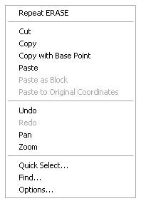
The top item on this menu is Repeat command, where command is the last command used. For example, if you just finished using the Erase command and you right-click your mouse, the top item of the shortcut menu is Repeat Erase. I’ll introduce the other items on this shortcut menu throughout the rest of the book. The shortcut menu is also called a context menu because the items on it depend on the following:
- Whether a command is running
- Which command you are using
- Where you are in a command
In this chapter, you will be introduced to several new commands and, through the step-by-step instructions, be shown some alternate methods for accomplishing tasks similar to those you have previously completed. You will add front and back steps, thresholds, a balcony, and kitchen and bath fixtures to the cabin floor plan (see Figure 5.1). For each of these tasks, the focus will be on noticing which objects and geometry are already in the drawing that can make your job easier and on tools to help you accomplish the tasks more quickly and efficiently.
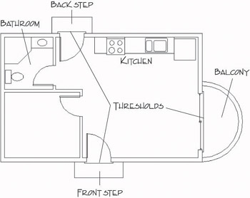
Figure 5.1: The cabin with front and back steps, thresholds, balcony, kitchen, and bathroom
Drawing the Steps and Thresholds
The steps and thresholds are each drawn with three simple lines. The trick is to see which part of the drawing you can effectively use to generate and position those lines. Use a width of 2' for the front and back steps, and use a length of 6' for the front step and 5' for the back step. The three thresholds extend 2" beyond the outside wall line and run 3" past either jamb line (see Figure 5.2). These are simple shapes to draw, but you will learn a few new techniques as you create them.
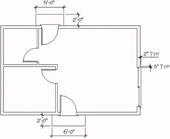
Figure 5.2: The steps and thresholds with their dimensions
The Front Step
As you can see in Figure 5.2, the front step is 2' wide and 6' long. Because you know the width of the doorway opening, you can determine how far past the opening the step extends, assuming it to be symmetrical. You can draw a line from the endpoint of one of the jamb lines, down 2', and then offset the proper distance left and right to create the sides of the step. Here’s how it’s done:
- With AutoCAD running, open your cabin drawing (last saved as Cabin04c), and use the Zoom command options to achieve a view similar to Figure 5.3.
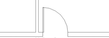
Figure 5.3: Zoomed in to the front opening - Check to be sure all buttons on the status bar except Model are in the off position. Start the Line command, activate the Endpoint Osnap, and pick a point at the lower end of the left jamb line.
Ways to Use the Object Snap Tools
You can access the Object Snap tools in several ways:
- The Object Snap toolbar might be docked on the right side of the drawing area. If not, you can display it and dock it.
- The Object Snap menu also contains Object Snaps. To open this menu, hold down the Shift key and click the right mouse button.
- If you’re using an Intellimouse or have a mouse with three buttons, you might be able to open the Object Snap menu by clicking the Intellimouse wheel or clicking the third mouse button.
- You can type the first three letters of any Object Snap to activate it, as in end for Endpoint.
- Right-click the Polar button on the status bar at the bottom of the screen, and then choose Settings from the shortcut menu to open the Drafting Settings dialog box. By default, the Polar Tracking tab is active.
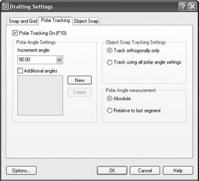
- In the Polar Angle Settings area, check whether Increment Angle is set to 90.00. If it’s not, open the drop-down list and select 90.00. On the right side, be sure that Absolute is selected in the Polar Angle Measurement area. Finally, in the upper-left corner, click the Polar Tracking On check box. Click OK.
For LT users, your Polar Tracking tab in the Drafting Settings dialog box won’t have the Object Snap Tracking Settings area because LT doesn’t have this feature.
- Hold the crosshair cursor so that it is below the first point picked. Do not pick a point yet (see Figure 5.4). A dashed line called a temporary alignment path is displayed along with a tool tip that identifies the alignment path as a Polar path; a relative polar coordinate confirms the angle to be 270. As you move the cursor from left to right, notice that the alignment path and tool tip disappear when you get too far from a point directly below the first point of the line, and they reappear as you get back close to vertical.
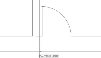
Figure 5.4: The Line command running with Polar Tracking on - While the alignment path and tool tip are visible, type 2'. A vertical line is drawn that is 2 feet long. When the Line command is running and the crosshair cursor is held away from the last point picked in a particular direction, you can enter a distance, and the line is drawn to the desired length in the direction of the crosshair cursor. This is called the Direct Entry method of entering distances. Because you want the line to be vertical, Polar Tracking assisted you by producing an alignment path in the vertical direction.
When Polar Tracking mode is on, temporary alignment paths assist you in drawing lines at angles that are multiples of the increment angle, in this case, 90.
- Press to end the Line command. Type o to start the Offset command. Type 1'6 for an offset distance, and offset this line to the left.
- Press twice to stop and restart Offset. Type 6' and offset this new line to the right (see Figure 5.5). Press to end the Offset command.
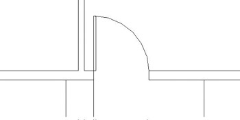
Figure 5.5: The sides of the front step after offsetting - Erase the original line, and then draw a line from the lower endpoints of these two new lines to represent the front edge of the step. Use the Endpoint Osnap for each point picked. Press to end the Line command. Your drawing should look like Figure 5.6.
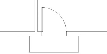
Figure 5.6: The completed front step - Zoom Previous to view the entire floor plan.
The strategy here was to recognize that a line drawn from the jamb line can be used to determine the location of the sides of the step. Using Polar Tracking to draw is a quick way to enter distances when the lines are at angles that are multiples of the Polar Tracking increment angle that you set. For the back step, you’ll build on this by adding the Temporary Tracking Point aid to your bag of tools.
The Back Step
You can apply the method used to draw the front step to the back step as well. The situation is identical: you will be working with the same geometry in the drawing and will accomplish the same thing. This time, however, you’ll use a Temporary Tracking Point to locate the side of the step. This will cut out the need to use a guideline. Remember that the step in the back is 5' wide.
LT does not have the Temporary Tracking Point tool, so LT users should skip to the sidebar in the middle of the following steps to get alternate instructions for steps 1 through 3.
- Zoom in to the back step area. Start the Line command and click the Temporary Tracking Point button on the Object Snap toolbar.
The prompt line in the Command window will read _line Specify first point: _tt Specify temporary OTRACK point:. This is actually three prompts grouped together:
- _line signifies the start of the Line command.
- Specify first point is the first prompt for the Line command.
- _tt Specify temporary OTRACK point signifies that the Temporary Tracking Point option has been selected.
In this case, because the step is 5' long, we want to begin the side of the step 1' to the left of the doorway opening. So the temporary tracking point that you need is the starting point from which you will measure the 1' distance—in this case, it is the upper end of the left jamb line.
- Select the Endpoint Osnap and pick the upper end of the left jamb line. A small cross appears at the point you just picked, and the prompt line now has _endp of Specify first point: added to it. This is actually two more prompts grouped together:
- _endp signifies that the Endpoint Osnap was selected.
- Specify first point is the second prompt for the Temporary Tracking Point option. AutoCAD has recorded the temporary tracking point and waits for you to specify the first point of the line that is to be the left side of the back step. You will do this by using Polar Tracking and Direct Entry, telling AutoCAD how far and in what direction from the temporary tracking point you want to begin the line—in this case, it’s 1' to the left.
- Hold the cursor to the left of the temporary tracking point. When the temporary alignment path appears with the tool tip, as shown in Figure 5.7, type 12. A line begins 1' to the left of the opening on the outside wall line. Hold the crosshair cursor directly above the beginning of the line, and when you see the vertical alignment path with the tool tip, type 2'. The side of the step is drawn using the Direct Entry technique with Polar Tracking. The Line command is still running.
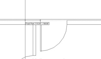
Figure 5.7: Using a temporary tracking point with Polar Tracking and Direct Entry
Steps 1 through 3 for LT Users
Here are instructions for LT users:
- Zoom in to the back step area. Start the Line command and click the Tracking button on the Object Snap toolbar. (The Tracking button is the one at the top.)
- Select the Endpoint Osnap and pick the upper end of the left jamb line.
- Hold the cursor out to the left of the point you picked, past the edge of the building, and type 12.Then hold the cursor directly above the point that was selected until the Polar Tracking lines and tool tips appear. Type 24.
Now continue with step 4.
- Hold the crosshair cursor directly to the right from the last point; then, when you see the alignment path and tool tip, type 5'. The front edge of the step is drawn. You used Direct Entry with Polar Tracking again, and you didn’t have to enter either the relative polar or the Cartesian coordinates.
- Select Perpendicular Osnap from the Object Snap toolbar, and move the cursor to the outside wall line (see Figure 5.8). When the perpendicular icon appears on the wall line, click the mouse button. The right edge of the step is drawn, and the back step is complete. Press to end the Line command.
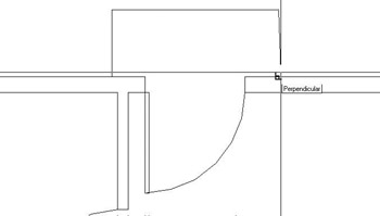
Figure 5.8: Completing the back step with the Perpendicular Osnap - Zoom Previous to view the completed back step with the whole floor plan.
Temporary Tracking is a handy tool for AutoCAD users. We’ll use it a few more times in this book. When you combine it with the technique of using Polar Tracking to help enter distances, as you have for the back step, you will be surprised at how quickly you can lay out orthogonal walls in a floor plan. The Polar Tracking technique, used by itself, powerfully facilitates drawing the footprint of a building. When you work through the next section, you’ll get to practice using the Temporary Tracking tool once more.
I’m sure this seems complicated, but you’ll get a chance to try the technique three more times, because you now have to do the thresholds for the three external openings.
The Thresholds
Thresholds generally are used on doorway openings when the level changes from one side of the opening to the other. This usually occurs at entrances that open from or to the outside. Though quite different in shape, each threshold for the cabin has the same geometry as the steps. The lip of each threshold is offset 2" from the outside wall, and each edge runs 3" past the doorjamb. (See Figure 5.2 earlier in this chapter.) You’ll use the Temporary Tracking Point tool with Polar Tracking and Direct Entry to draw the three thresholds for the cabin.
For LT users, reuse the steps in the “Steps 1 through 3 for LT Users” sidebar in the previous section to complete the exercise in this section. You draw the thresholds using the same procedure you used for the back step.
Here are the steps to draw a threshold for one of the openings. I’ll use the front door entry for the illustrations.
- Zoom in to the opening and its immediate surroundings.
- Start the Line command, and then click the Temporary Tracking Point button and the Endpoint Osnap button on the Osnap toolbar.
- Click the outside endpoint of one of the jamb lines, and then move the cursor along the wall line away from the opening until the Polar alignment path and tool tip appear (see Figure 5.9a).
- Enter the distance that the threshold extends past the jamb. (It’s 3".) This begins the first line.
- Move the crosshair away from the wall line in a horizontal or vertical direction (depending on which opening you are drawing) until the Polar alignment path and tool tip appear (see Figure 5.9b).
- Enter the overhang distance of the threshold. (It’s 2".)
- Move the crosshair in a direction perpendicular to the last point of the last segment drawn, until the Polar alignment and tool tip appear.
- Enter the length of the threshold. (It’s the length of the opening + 6".)
- Invoke the Perpendicular Osnap and hold the crosshair back on the wall line; then click. Press to end the Line command (see Figure 5.9c).
- When finished, Zoom Previous to view the finished thresholds with the rest of the drawing.
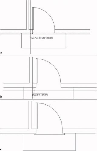
Figure 5.9: The tracking path and Track Point tool tip (a), the first threshold line is started (b), and the completed threshold (c)
Using Direct Entry of Distances
Direct Entry is a method used to specify distances for line segments. You position the crosshair in such a way that the direction from the last point picked indicates the direction for the next line segment. You then just type the distance. There’s no need to use either the relative polar or the relative Cartesian coordinates. You primarily use this technique with Polar Tracking to draw line segments that are oriented at a preset angle, in this case, 90, 180, 270, and 0. It saves time because there is less data to type. You can also use Direct Entry with the Copy and Move commands to specify displacement of selected objects being moved or copied.
The tracking features in AutoCAD are powerful tools for drawing that you can use in several ways. So far we have used Polar Tracking and the Temporary Tracking Point Osnap, and we’ll use them again and other tracking features later in this chapter.
The Balcony Drawing Circles
A glance back at Figure 5.1 will tell you that the balcony is made up of two semi-circles. You can draw these in several ways, but here you will form them from a circle. Often the easiest way to draw an arc is to draw a circle that contains the arc segment and then trim the circle back.
- Choose Draw Circle and look at the Circle menu for a moment.
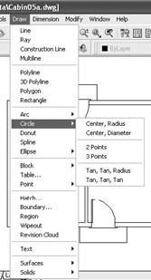
You have six options for constructing a circle. The first two require you to specify a point as the center of the circle and to enter a radius or a diameter. You use the next two when you know two or three points that the circle must intersect. And finally, the last two options use tangents and a radius or just tangents to form a circle.
- The balcony has a radius of 5', so choose the Center, Radius option. The Command window prompts you to specify a point as the center of the circle. The actual center for the balcony will be 5' above the lower-right corner of the outside wall line, but for this exercise, we will draw the circle in the living room and then move it into position later.
- Pick a point in the middle of the largest room of the cabin. The center is now established, and as you move the cursor, the circle changes size and becomes attached to the crosshair cursor (see Figure 5.10). You could pick a point to establish the radius, but in this case, you know exactly what you want the radius to be.
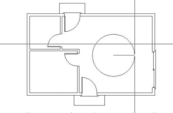
Figure 5.10: The circle attached to the crosshair cursor - Type 5'. The circle is drawn, and the command ends.
- Click the Move button on the Modify toolbar. The cursor changes to a pickbox. Select the circle and press .
- On the Object Snap toolbar or flyout, click the Quadrant button. Select the circle somewhere near its bottom extremity (see Figure 5.11a). An image of the circle is attached to the crosshair cursor. Turn Polar Tracking off by clicking the Polar button on the status bar.
- Move the crosshair cursor around to see that the lowest point on the circle is attached at the crosshair (see Figure 5.11b). You need to place this point on the circle at the lower-right corner of the outside wall line.
- Select the Endpoint Osnap, and then pick the lower-right corner of the cabin. The circle is positioned correctly for the balcony (see Figure 5.11c). Now you can use the existing wall lines to trim the circle into a semicircle.
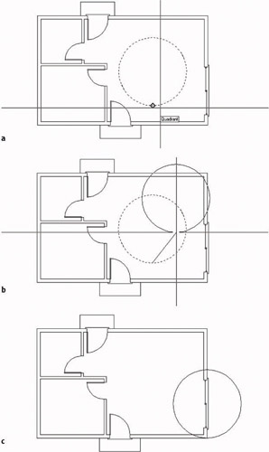
Figure 5.11: Selecting the base point with Quadrant Osnap (a), the circle attached to the crosshair cursor at its lowest point (b), and the circle positioned for the balcony (c) - Zoom in to the area of the balcony and start the Trim command.
- Select the two outside wall lines on the far right, as shown in Figure 5.12, and then right-click.
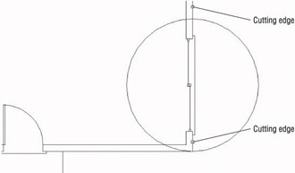
Figure 5.12: Selecting wall lines to be cutting edges - Select the portion of the circle that is inside the cabin. The circle is trimmed into a semicircle. Press to end the Trim command.
- Start the Offset command, set the distance for 6", and offset the semi-circle to the inside. Press to end the Offset command. The balcony is complete. Zoom Previous to view the floor plan with the completed balcony. Save the drawing as Cabin05a.dwg (see Figure 5.13).
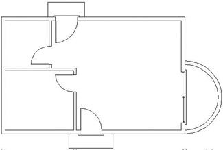
Figure 5.13: The floor plan with the balcony completed
As mentioned at the beginning of this section, you can use several techniques to draw the balcony. The one you used gave you the opportunity to use the Move command and the Quadrant Osnap, and it let you see how using the lowest quadrant snap point on the circle is an easy way to locate the balcony on the building. No entry of relative coordinates was required.
In the next section, you will continue to develop drawing strategies as you focus on laying out a counter and fixtures to complete the kitchen.
Laying Out the Kitchen
The kitchen for the cabin will have a stove, a refrigerator, and a counter with a sink (see Figure 5.14). The refrigerator is set 2" from the back wall. Approaching this drawing task, your goal is to think about the easiest and fastest way to complete it. The first step in deciding on an efficient approach is to ascertain what information you have about the various parts and what geometry in the drawing will be able to assist you. Figure 5.14 gives you the basic dimensions, and you will get more detailed information about the sink and stove as we progress through the exercise.
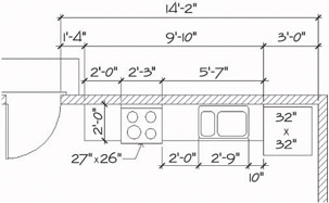
Figure 5.14: The general layout of the kitchen
The Counter
Although the counter is in two pieces, you will draw it as one piece and then cut out a section for the stove. Try two ways to draw the counter to see which method is more efficient.
Using Polar Tracking and Direct Entry with a Temporary Tracking Point
- Use a zoom window to zoom your view so it is about the same magnification as Figure 5.15. On the status bar, click the Polar button to turn Polar Tracking back on if it is not already on. The Model and Polar buttons should be in the on position. The rest of the buttons should be off.
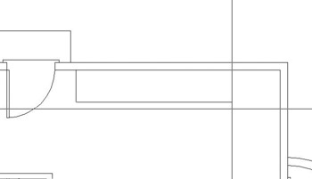
Figure 5.15: Drawing the counter using the Direct Entry technique - Start the Line command. Activate the Temporary Tracking Point Osnap and click Endpoint Osnap. Then pick the lower end of the right back doorjamb line. A small cross is placed on the point you choose.
LT users should use steps 2 and 3 in the following “Steps 2 and 3 for LT Users” sidebar instead of these.
- Hold the crosshair cursor directly to the right of that point. When the Track Point tool tip and the dotted-line tracking path appear, type 1'4. The line for the left side of the counter is begun.
Steps 2 and 3 for LT Users
Here are instructions for LT users:
- Start the Line command. Click the Tracking button at the top of the Object Snap toolbar, and click Endpoint Osnap. Then pick the lower end of the right back doorjamb line.
- Hold the cursor directly to the right of the point you picked and type 1'4.Then press again. This begins the counter line on the inside wall line 1'-4" to the right of the point you originally picked.
Now continue with step 4 to complete the counter.
- Hold the crosshair cursor directly below the first point of the line and type 2'. Hold the crosshair cursor to the right and type 9'10 (see Figure 5.15, shown earlier). Select the Perpendicular Osnap and pick the inside wall line again. Press to end the Line command. The counter is drawn.
Using Offset and Fillet
To do the same thing using the Offset command, you’ll need to undo the effects of the previous command. Because all lines were drawn in one cycle of the Line command, one use of the U command will undo the entire counter.
- Click the Undo button on the Standard toolbar. The counter you just drew should disappear. If you ended the Line command while drawing the counter and had to restart it before you finished, you might have to click the Undo button more than once. If you undo too much, click the Redo button, which is just to the right of the Undo button.
Now draw the counter again, this time using the Offset and Fillet commands.
- Offset the right inside wall line 3' to the left. Then offset this new line 9'-10" to the left. Finally, offset the upper inside wall line 2' down (see Figure 5.16).
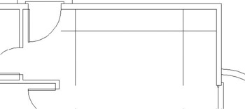
Figure 5.16: Offsetting wall lines to create the counter - Use the Fillet command with a radius of zero to clean up the two corners.
You can decide which of the two methods is more practical for you. Both are powerful techniques for laying out orthogonal patterns of lines for walls, counters, and other objects.
Undoing and Redoing in AutoCAD
AutoCAD has two Undo commands, and they operate quite differently.
- When you click the Undo button on the Standard toolbar, you are using AutoCAD’s U command. You can also start it by typing u. The U command works like the Undo command for Windows-compatible applications by undoing the results of commands one step at a time.
- The Undo command in AutoCAD has many options, and you start it by typing undo. You use this approach when you want to undo everything you’ve done since you last saved your drawing or to undo back to a point in your drawing session that you marked earlier. Be careful when you use the Undo command; you can easily lose a lot of your work.
The Redo command will undo the effect of several undos. So if you undo a few steps too many, you can still get them back.
The Stove and Refrigerator
The stove and refrigerator are simple rectangles. Use the Temporary Tracking Point Osnap to locate the first corner of each shape.
- For the refrigerator, click the Rectangle button on the Draw toolbar, and then click the Temporary Tracking Point Osnap option. Use Endpoint Osnap to select a base point at the upper end of the right side of the counter. Then hold the cursor directly below that point. When the dotted tracking path and the Track Point tool tip appear, type 2. This starts the rectangle 2" from the back wall, along the side of the counter. To specify the opposite corner of the rectangle, type @32,-32.
LT users should use steps 1 through 3 in the following “Steps 1 through 3 for LT Users” sidebar instead of these.
- For the stove, right-click the mouse, and choose Repeat Rectangle from the shortcut menu that opens. Use the technique that was used in step 1, but pick the upper end of the left side of the counter as the tracking point. Hold the cursor directly to the right of that point and type 2’. Then type @27,-26 to complete the rectangle.
- Use the Trim command to trim away the front edge of the counter at the stove (see Figure 5.17).
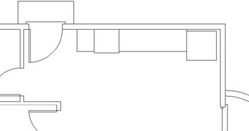
Figure 5.17: The stove and refrigerator made with rectangles
Steps 1 through 3 for LT Users
Here are instructions for LT users:
- For the refrigerator, click the Rectangle button on the Draw toolbar, and then click the Tracking button at the top of the Object Snap toolbar. Use Endpoint Osnap to select a base point at the upper end of the right side of the counter. Then hold the cursor directly below that point and type 2.This starts the rectangle 2" from the back wall, along the side of the counter. To specify the opposite corner of the rectangle, type @32,-32.
- For the stove, right-click the mouse and choose Repeat Rectangle from the shortcut menu that opens. Use the technique that was used in step 1, but pick the upper end of the left side of the counter as the tracking point. Hold the cursor directly to the right of that point and type 2’.Then type @27,-26 to complete the rectangle.
- Use the Trim command to trim away the front edge of the counter at the stove (see Figure 5.17, shown earlier).
Note Because the stove rectangle is drawn as a polyline—a special line in which all segments compose one unique entity—you need to select only one segment of it for all sides of the rectangle to be selected and, in this case, to become cutting edges.
Completing the Stove
The stove needs a little more detail. You will need to add circles to represent the burners and to add a line off the back to indicate the control panel (see Figure 5.18). The burners are located by their centers.
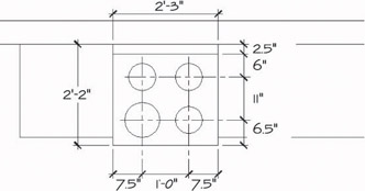
Figure 5.18: The details of the stove
- Zoom in to a closer view of the stove using the zoom window. You need to draw a line along the back of the stove that is 2.5" in from the wall line. Offsetting seems like the right command to use.
- Offset the wall line down 2.5". When you pick the line, pick it somewhere to the right or left of the stove. Then after it’s offset, trim it back to the sides of the stove (see Figure 5.19).
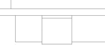
Figure 5.19: The stove with the control panel drawnWarning The back segment of the stove coincides with the wall. If you try to pick the wall line where the two lines coincide, you might pick the rectangle of the stove instead. You don’t want to offset a line of the stove because it is a polyline. When any segment of a polyline is offset, all segments are offset, and all corners are filleted automatically. This would be an inconvenience in this situation because only one line segment needs to be offset. When you draw the sink, you’ll learn a technique for selecting the line you want when two or more lines overlap or coincide.
- The next step is to lay out guidelines to locate the centers of the burners. Offset the line you created for the control panel in step 2 down 6". Then offset this new line down 11". Next you need vertical guidelines. Use tracking to draw the first guideline.
- Start the Line command and select Temporary Tracking Point Osnap and then Endpoint Osnap. Then pick the upper-left corner of the stove.
LT users need to use the Tracking tool for Steps 4 and 5. Use the same method you used for the refrigerator and the counter.
- Hold the cursor directly to the right of this point. When the dotted tracking path and the Track Point tool tip appear, type 7.5. The first guideline is started.
- Hold the crosshair cursor below the first point of the guideline and pick a point just below the stove. Press to end the Line command.
- Offset this line 12" to the right (see Figure 5.20). The guidelines are set in place.
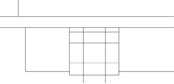
Figure 5.20: The guidelines for the centers of the burner circles
The next step is to draw a circle for one burner, copy it to the other three burner locations, and then change the radius of the left front burner.
- Using the Intersection Osnap and the Circle command, draw a circle with its center at the lower-left intersection of the guidelines and with a radius of 3.5".
- Start the Copy command. Select the circle and then press .
- Type m to start the Multiple option. Choose Intersection Osnap. Select the intersection of the guidelines at the center of the circle as a base point.
- Select the Intersection Osnap again, and pick the intersection of guidelines above the first circle (see Figure 5.21). Select the Intersection Osnap again, and pick one of the intersections on the right side. Then select the Intersection Osnap one more time, and pick the fourth intersection of guidelines. Press to end the Multiple Copy command. The burners are in place. Now you need to change the size of the lower-left burner.
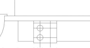
Figure 5.21: The first burner is copied. - Pick the lower-left burner. Five grips will appear on the circle and at its center.
- Click the Properties button near the right end of the Standard toolbar to open the Properties palette. It will fill most of the left part of the screen (see Figure 5.22). Notice the drop-down list at the top of the Properties palette. This tells you that the currently selected object is a circle.
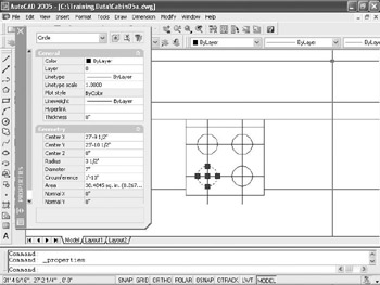
Figure 5.22: The Properties palette and the selected burner - Move down the categorized list of properties and click Radius.
- Highlight the 3.5" Radius setting. Change it to 4.5" and press . The burner in the drawing is enlarged.
- Click the X in the upper-left corner of the Properties palette to close it. Then press the Esc key to turn off the five grips that were on the circle.
- Erase the guidelines, and the stove is completed (see Figure 5.23). Zoom Previous to see the whole kitchen with the completed stove.
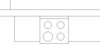
Figure 5.23: The completed stove
With the stove finished, the final task in the kitchen is to draw the sink.
| Note |
The Properties palette is an important tool for working with objects in a drawing. You will learn more about it in Chapter 6, and you will use it throughout the rest of this book. |
The Kitchen Sink
You will draw a double sink, with one basin larger than the other (see Figure 5.24). You will use Offset, Fillet, and Trim to create the sink from the counter and wall lines.
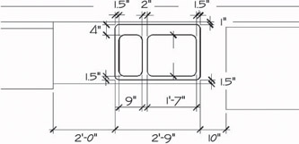
Figure 5.24: The sink with dimensions
- Zoom in to the sink area, keeping the edges of the refrigerator and stove in view. Offset the wall line 1" down and the front edge of the counter 1.5" up.
- Start the Offset command, and set the offset distance to 10". We’re going to offset the right side of the counter 10" to the left, but it coincides with the left side of the refrigerator. Hold down the Ctrl key as you pick that line. Then release the Ctrl key. If the refrigerator ghosts, pick the same line again. The selected line will switch to the line representing the edge of the counter. When the counter edge is selected, press , and then complete the offset by picking a point to the left of the selected line. This selection technique is called cycling. It allows you to select a line that may coincide with another line.
When we drew the detail onto the stove, we could have used cycling to select the wall line where it coincided with the stove outline. We didn’t need to because we could easily select the wall line at a point where the stove outline wasn’t interfering.
- Offset this new line 2'-9" to the left. This forms the outside edge of the sink (see Figure 5.25a).
- Fillet the corners of this rectangle to clean them up, using a radius of zero.
- Offset the left side, bottom, and right side of the sink 1.5" to the inside. Offset the top side 4" to the inside. Then offset the new line on the left 9" to the right and then again 2" farther to the right. This forms the basis of the inside sink lines (see Figure 5.25b).
- Trim away the horizontal top and bottom inside sink lines between the two middle vertical sink lines. Then fillet the four corners of each sink with a 2" radius to clean them up.
- Fillet all outside sink corners with a 1.5" radius. This will finish the sink (see Figure 5.25c). Zoom Previous to view the whole kitchen with the completed sink.
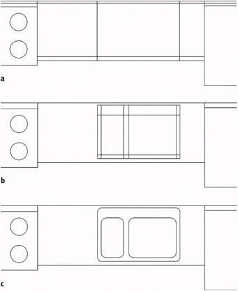
Figure 5.25: The offset lines to form the outside edge of the sink (a), the offset lines to form the inside edges of the sink (b), and the finished sink (c)
This completes the kitchen area. You drew few new lines to complete this task because most of them were created by offsetting existing lines and then trimming or filleting them. Keep this in mind as you move on to the bathroom.
Constructing the Bathroom
The bathroom has three fixtures: a sink, a shower, and a toilet (see Figure 5.26). In drawing these fixtures, you will be using a few Object Snaps over and over again. You can set one or more of the Osnap choices to be continually running until you turn them off. That way, you won’t have to select them each time.
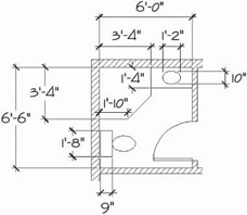
Figure 5.26: The bathroom fixtures with dimensions
Setting Running Object Snaps
You will set only two Osnaps to run continually for now, until you get used to how they work.
- Right-click the Osnap button on the status bar, and choose Settings from the shortcut menu to open the Drafting Settings dialog box. By default, the Object Snap tab is on top.
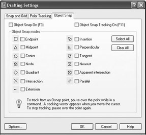
Each of the 13 Osnap options (11 options for LT) has a check box and a symbol next to it. The symbol appears in the drawing when a particular Osnap is selected and the cursor is near a point where that Osnap can be used. You can check any number of Osnaps to be running at a time.
LT users’ Object Snap tab will not have all the Object Snap modes, the Object Snap Tracking On check box, and the Osnap tracking explanation at the bottom, because LT doesn’t have these features. We’re not using any of these features right now, anyway.
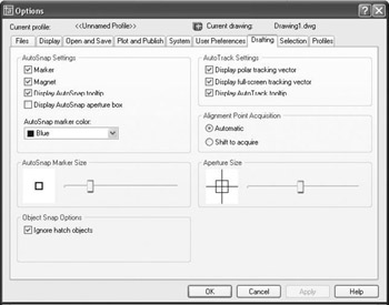
Note The symbols or icons that appear on an object when an Osnap is active and when you move the cursor near the object are called AutoSnaps. They’re quite helpful, and you can choose a different color for them if you want. If you’re using a dark background in the drawing area, use a bright color, such as yellow. For a white background, try blue.
- In the lower-left corner of the Drafting Settings dialog box, click Options to open the Options dialog box; the Drafting tab should be on top. Then on the left side in the AutoSnap Settings area, open the AutoSnap Marker Color drop-down list and select a color. While you’re in this area, make sure the Marker, Magnet, and Display AutoSnap Tool Tip check boxes are selected. Also make sure that the Display AutoSnap Aperture Box is unchecked. Then click OK.
LT users won’t have all the settings on the right side of the Drafting tab.
- Back in the Object Snap tab of the Drafting Settings dialog box, click the check boxes next to Endpoint and Midpoint. Then above the list and to the left, be sure there’s a check mark in the box next to Object Snap On. Click OK to close the dialog box. These Osnaps will now be active any time you are prompted to select a point on the drawing.
Now you are ready to begin drawing the three fixtures for the bathroom. The shower determines the placement of the other two, so let’s start there.
Drawing a Shower Unit
You will start the shower unit with a square and then trim away one corner. As you start this exercise, check the status bar. The Polar, Osnap, and Model buttons should be in the on position. The rest of the buttons should be off.
- Type zp to Zoom to Extents. Then use the zoom window to view the bathroom close-up. Start the Rectangle command. For the first point, move the cursor to the upper-left inside corner of the room. Notice the square that appears at the corner. This is the AutoSnap symbol for the Endpoint Osnap. As soon as it appears on the endpoint you want to snap to, click the left mouse button. The first corner of the square is placed. For the second point, type @40,-40.
Tip If you don’t get the square you want after entering the relative coordinates for the second corner, check this setting. Choose Tools Options to open the Options dialog box. Click the User Preferences tab. In the upper-right corner of the Priority For Coordinate Data Entry area, be sure that the button next to Keyboard Entry Except Scripts is active. Then click OK. Try the square again.
- Start the Line command, and move the cursor near the midpoint of the bottom line of the square. Notice that a triangle, the Midpoint AutoSnap symbol, appears when you get near the midpoint of the line. When you see the triangle on the midpoint you want, click.
- Move the cursor near the midpoint of the right side of the rectangle until you see the triangle appear at the midpoint location (see Figure 5.27). Click again. Press to end the Line command.
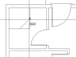
Figure 5.27: Using Midpoint Osnap to complete a line across the corner of the shower - Use this line as a cutting edge, and trim away the lower-right corner of the shower rectangle. The trimming will require only one pick because you are trimming a polyline. Press to stop the Trim command. This completes the shower.
Next, draw the sink to the right of the shower.
The Bathroom Sink
You will offset a line and draw an ellipse for this fixture, while practicing the Temporary Tracking Point Osnap option in the process. The Endpoint and Midpoint Osnaps are still running.
- Zoom in to the sink area with a zoom window. Offset the top inside wall line down 16". Then use the shower wall as a cutting edge and trim back the line.
- Click the Ellipse button on the Draw toolbar. Type c to select the Center option.
- Click the Temporary Tracking Point Osnap button, and then move the cursor near the midpoint of the newly offset line. When the AutoSnap symbol appears at the midpoint of this line, click. This establishes a tracking point (a small cross).
LT users will need to follow steps 3 and 4 in the following “Steps 3 and 4 for LT Users” sidebar instead of these.
- Move the crosshair cursor directly above the tracking point. When the dotted tracking path and the Track Point tool tip appear, type 8 to locate the center of the counter. The Command window will prompt you for the location of the ends of two perpendicular axes. You will start with the left/right axis and enter the distance using Direct Entry and Polar Tracking, as you did for the steps earlier in this chapter.
- Hold the crosshair cursor directly to the right of the center point. Type 7. Hold the crosshair cursor directly above the center and type 5. The ellipse is constructed, and the sink fixture is complete (see Figure 5.28). Leave the view on your screen as it is for a moment.
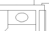
Figure 5.28: The completed sink fixture
Steps 3 and 4 for LT Users
Here are instructions for LT users:
- Click the Tracking button at the top of the Object Snap toolbar, and then move the cursor near the midpoint of the newly offset line. When the AutoSnap symbol appears at the midpoint of this line, click. This establishes a tracking point.
- Move the crosshair cursor directly above the tracking point and type 8 to locate the center of the counter. Press again to end Tracking and continue with the Ellipse command. The Command window will prompt you for the location of the ends of two perpendicular axes. You will start with the left/right axis and enter the distance using Direct Entry and Polar Tracking, as you did for the steps earlier in this chapter.
Drawing the toilet is the final task in this chapter. You will use the Ellipse command again, along with the Rectangle command. You will also be introduced to a couple of new display options.
Positioning a Toilet
The toilet consists of a rectangle and an ellipse centered between the shower and the wall. The tank is offset 1" from the back wall and is 9" 20". The ellipse representing the seat measures 18" in one direction and 12" in the other.
- On the Standard toolbar, click the Pan Realtime button. The cursor changes to a small hand when you return it to the drawing area. Position it in the lower-left corner of the drawing area with the view still zoomed in on the sink.
- Hold down the left mouse button and drag the hand up and to the right. When the toilet area comes into view, release the mouse button. The drawing slides along with the movement of the cursor. If necessary, do this again until you have the toilet area centered in the drawing area.
- Right-click the mouse, and choose Zoom from the shortcut menu that opens. Back on the drawing, the cursor changes to a magnifying glass with a plus and minus sign.
- Position the Zoom Realtime cursor near the top of the drawing and hold down the left mouse button. Drag the cursor down, and watch the view being zoomed out in real time. Move the cursor up, still holding the mouse button down. Position the cursor in such a way that you have a good view of the toilet area, and then release the mouse button. Right-click again, and choose Exit from the shortcut menu to end the Zoom Realtime command.
With Zoom Realtime, moving the cursor to the left or right has no effect on the view. The magnification is controlled solely by the up-and-down motion.
These zooming options are convenient tools for adjusting the view of your drawing. Let’s move on to the toilet. You need to find a way to position the toilet accurately, centering it between the wall and shower. The midpoint of the left wall line won’t be useful because the wall line runs behind the shower. You will have to construct a guideline.
- With the Rectangle command, draw the toilet tank a few inches to the right of the wall, not touching any lines. (See Figure 5.26, shown earlier, for the dimensions.) Then offset the left wall line 1" to the right to make a guideline. Use the shower as a cutting edge, and trim this guideline down to the shower (see Figure 5.29a).
- Start the Move command, select the tank, and then press .
- For the base point, move the cursor to the middle of the left side of the tank. When you see the triangle at the midpoint, click the left mouse button.
- For the second point, move the cursor onto the guideline. When it gets closer to the midpoint than the endpoint, the triangle will appear at the midpoint. At this point, click the left mouse button. The rectangle is accurately positioned 1" from the left wall and centered between the shower and lower wall (see Figure 5.29b).
- Erase the guideline.
- Start the Ellipse command. The Command window displays a default prompt of Specify axis endpoint of ellipse or [Arc/Center]:. Using the Specify Axis endpoint option, you can define the first axis from one end of the ellipse to the other. This will help you here.
- Move the cursor near the midpoint of the right side of the tank and, when the triangle shows up there, click. This starts the ellipse.
- Hold the crosshair cursor out to the right of the rectangle and type 1'6. The first axis is positioned. Now as you move the crosshair cursor, you will see that a line starts at the center of the ellipse, and the cursor’s movement controls the size of the other axis (see Figure 5.29c). To designate the second axis, you need to enter the distance from the center of the axis to the end of it, or half the overall length of the axis.
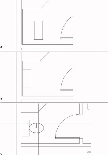
Figure 5.29: The toilet tank with an offset guideline (a), the tank correctly positioned (b), and the cursor controlling the size of the second axis for the toilet seat (c) - Hold the crosshair cursor directly above the center point and type 6. The ellipse is complete, and the toilet is finished.
- In the status bar, right-click the Osnap button, and then choose Settings from the shortcut menu to open the Settings dialog box. The Object Snap tab will be in front. Click the Clear All button to turn off all running Osnaps. Click OK to close the dialog box.
- Before you save this drawing, use the Pan Realtime and Zoom Realtime commands to zoom out and pan your drawing until the whole floor plan fills the drawing area, except for a thin border around the outside of the plan (see Figure 5.30). Save this drawing as Cabin05b.
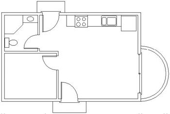
Figure 5.30: The completed floor plan zoomed and panned to fill the screen
The bathroom is complete, and you now have a fairly complete floor plan for the cabin. In completing the drawing tasks for this chapter, you have been exposed to several new commands and techniques to add to those introduced in Chapter 4. Combined, you now have a set of tools that will take you a long way toward being able to lay out a drawing of any size.
Chapters 1 through 5 fill out the basic level of skills in AutoCAD that allow you to draw on the computer approximately as you would with pencil and vellum, though you may already see some of the advantages CAD offers over traditional board drafting. Beginning with the next chapter, you will be introduced to concepts of AutoCAD that do not have a counterpart in board drafting. These features will take you to a new level of knowledge and skill, and you will start to get an idea of what sets computer drafting apart.
Using Realtime Pan and Realtime Zoom
The Realtime Pan and Zoom buttons are next to each other on the Standard toolbar. You can start Realtime Pan by typing p. You can start Realtime Zoom by typing z. You can also start Realtime Pan or Zoom by right-clicking at the Command: prompt and then choosing Pan or Zoom from the shortcut menu. If you try this, you will find that it is easier than clicking the Realtime Pan or Zoom buttons.
Once one of these Realtime commands is running, you can switch to the other one by clicking the other Realtime button or by right-clicking and choosing the other one from the shortcut menu. The shortcut menu also has other options that help make Realtime Pan and Zoom quite useful commands.
ExitEnds the Realtime Zoom or Pan commands.
PanSwitches to Realtime Pan from Realtime Zoom.
ZoomSwitches to Realtime Zoom from Realtime Pan.
3D OrbitA special viewing tool for 3D that is covered in the Appendix.
Zoom WindowAllows you to make a zoom window without first ending Realtime Pan or Zoom. You pick a point, hold down the left mouse button, and then drag open a window in your drawing. When you release the button, you are zoomed into the window you made, and Realtime Pan or Zoom resumes.
Zoom OriginalRestores the view of your drawing that you had when you began Realtime Pan or Zoom.
Zoom ExtentsZooms to the drawing Extents.
To end Realtime Pan or Zoom, press the Esc key, press , or right-click and choose Exit from the shortcut menu.
When Realtime Pan or Zoom is running, AutoCAD is in a special mode that makes the status bar and the Grid (if it is on) invisible and therefore unusable.
If You Would Like More Practice
Following are several additional exercises that will give you the opportunity to practice the skills and techniques you have learned up until now.
Draw the Cabin Again
As is true for almost any skill, the key to mastery is practice. Redrawing the entire cabin may seem daunting at this point when you think of how long it took you to get here. But if you try it all again, starting with Chapter 3, you will find that it will take about half the time that it did the first time, and if you do it a third time, half that time again. Once you understand the techniques and how the commands work, feel free to experiment with alternative techniques to accomplish tasks and with other options on the commands.
Draw Something Else
If you have a specific project in mind that you would like to draw in AutoCAD, so much the better—try it.
Draw Some Furniture for the Cabin
Once you put some furniture in the cabin, you will quickly see how small it is! But it can still accept some basic furniture without seeming too cramped. You should be able to add the following:
- Kitchen—a table and chairs
- Living room—a short couch, coffee table, and easy chair
- Bedroom—a double bed, dresser, and side table
Use a tape measure, and go around your office or home to determine the approximate dimensions of each piece. The goal here is not so much accuracy of scale but to practice drawing in AutoCAD. Figure 5.31 shows the floor plan with these items of furniture. If you draw the bed that I show here, try using the Spline tool for the curved, turned-down sheets. It’s in the middle of the Draw toolbar. You’ll see how it works after a little experimentation.
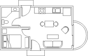
Figure 5.31: The floor plan with furniture
Draw a Gasket
Figure 5.32 shows a gasket that is symmetrical about its vertical and horizontal axes. This symmetry will allow you to use the Mirror command to create much of the drawing.
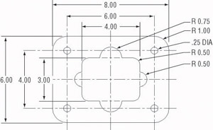
Figure 5.32: A gasket
The following diagrams summarize the steps.
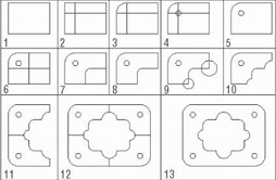
To draw the gasket, set the Linear Units to Engineering with a precision of 0'-0.00". Set the Angular units to Decimal with a precision of 0.00. Now follow these steps:
- Use the Line command to draw a rectangle 4" wide and 3" high.
- Offset the upper horizontal line and the left vertical line 1" to the inside of the rectangle.
- Use Fillet with a radius set to 1" on the upper-left corner of the original rectangle.
- Draw the circle with the 0.25" radius using the intersection of the two offset lines as the center.
- Erase the offset lines.
- Offset the right vertical line 2" to the left and the bottom horizontal line 1.5" up.
- Use Fillet with a radius of 0.50" on the intersection of these two lines, retaining the right and lower segments.
- Trim back the lower-right corner of the original rectangle.
- Draw circles with 0.50" and 0.75" radii on the bottom and right sides of the shape.
- Use Trim and Erase to remove unneeded lines.
- Use Mirror to flip the shape down.
- Use Mirror again to flip the shape to the right.
- Erase unneeded lines. (Each line to be erased is really two lines.)
Draw a Parking Lot
Here is a parking lot partially bordered by sidewalks and streets (see Figure 5.33).
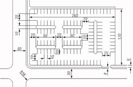
Figure 5.33: A parking lot
You will get a lot of practice using the Offset and Fillet commands. Guidelines will help you, so don’t be afraid to use them. Here’s a summary of the steps:
- Set Linear and Angular units to Decimal, each with a precision of 0. Assume that 1 linear decimal unit equals 1'. Set Polar Tracking to 90 and turn it on. Set Endpoint and Midpoint Osnaps to be running. Set the Snap to 10, Grid to 0, and Drawing Limits to 400, 250. Zoom All.
- Use Grid and Snap to draw the large 260' 170' rectangle using the Line command and relative Cartesian coordinates as you did in Chapter 3. Offset three of the lines 6' to the outside to make the sidewalk.
- On two sides, offset the outer sidewalk line 4' to the outside to make the curb. Then offset the curb lines 30' and 40' to make the street.
- Draw extra lines to make the street intersection.
- Fillet and Trim lines to create the curved corners of the intersection and sidewalks.
- Offset the lines of the inner rectangle to the inside to make guidelines for the parking strips and islands.
- Use Fillet and Trim to finish the drawing.
Tip Using Fillet on two parallel lines creates a semicircle to connect them. Try it on the islands in the parking area.
Are You Experienced?
Now you can
- use the Temporary Tracking Point tool to create and use tracking points
- use the Quadrant and Intersection Osnaps
- set up and use running Osnaps
- move around the drawing area with Realtime Zoom and Pan
- use the Circle and Ellipse commands
- move and duplicate objects with the Move and Copy Multiple commands
- use a circle and the Trim command to make a semicircle arc
- use guidelines to locate the center of circles for a stove top
Introduction
- Getting to Know AutoCAD
- Basic Commands to Get Started
- Setting Up a Drawing
- Gaining Drawing Strategies: Part 1
- Gaining Drawing Strategies: Part 2
- Using Layers to Organize Your Drawing
- Grouping Objects into Blocks
- Generating Elevations
- Working with Hatches and Fills
- Controlling Text in a Drawing
- Dimensioning a Drawing
- Managing External References
- Using Layouts to Set Up a Print
- Printing an AutoCAD Drawing
- Appendix A Look at Drawing in 3D
EAN: N/A
Pages: 159
