VERTEX SHADERS
|
|
To quote the Microsoft DirectX 8.0 documentation,
Vertex processing performed by vertex shaders encompasses only operations applied to single vertices. The output of the vertex processing step is defined as individual vertices, each of which consists of a clip-space position (x, y, z, and w) plus color, texture coordinate, fog intensity, and point size information. The projection and mapping of these positions to the viewport, the assembling of multiple vertices into primitives, and the clipping of primitives is done by a subsequent processing stage and is not under the control of the vertex shader.
What does this mean? Well, it means that whatever your input from the vertex streams (because you will have specified these values), the output from a vertex shader for a single pass will be
-
One single vertex in clip-space coordinates
-
Optional color values (specular and diffuse)
-
Optional texture coordinates
-
Optional fog intensity
-
Optional point sizing
This is shown in Figure 4.4.
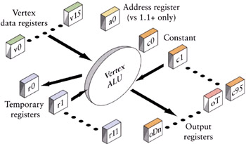
Figure 4.4: Vertex operations take input from vertex stream(s) and constants, and place the results in output registers.
So, at the very least your minimal vertex shader needs to take the object's vertex positions and transform them into clip-space coordinates. The optional parts are determined by the rendering state. Since the object has to be rendered with some properties, you'll have texture coordinates and/or color specifications as output. But the constant and absolute requirement for every vertex shader is that you provide vertex positions in clip-space coordinates. Let's start with that.
Our first vertex shader will do just that, transform the untransformed input vertex to clip space. There are two assumptions in the following code. The first is that the input vertex position shows up in shader register vO. The actual register number depends on the vertex shader input declaration, which tells the shader the format of the input stream. The second is that we've stored the world-view-projection matrix in the vertex shader constants. Given those assumptions, we can write the following shader:
// v0 -- position // c0-3 -- world/view/proj matrix // the minimal vertex shader //transform to clip space dp4 oPos.x, v0, c0 dp4 oPos.y, v0, c1 dp4 oPos.z, v0, c2 dp4 oPos.w, v0, c3
This shader uses four of the dot product shader instructions to perform a matrix multiply using the rows of the world-view-projection matrix sequentially to compute the transformed x, y, z, and w values. Each line computes a value and stores the scalar result into the elements of the output position register. Note that this is usually how the first few lines of your shader will look. It's possible that you might not need to perform the matrix multiply (e.g., if you transform the vertex before the shader is run). In any case, the minimal valid vertex shader must set all four elements of the oPos register.
There are some tricky issues with performing transformations, so let's review what this section of the shader has to do and what pitfalls there are. Along the way, we'll discuss some DirectX C++ code to perform the setup the shader requires.
Transformations and Projections
Typically, you'll start out with your object in what are called "object" or "model" coordinates—that is, these are the vertex positions that the model was originally read in with. Most of the projects I've worked on have created them with the object centered about the origin. Static objects might get an additional step where their vertices are transformed to some location in world space and then never touched again—creating a group of trees from a single set of original tree vertex coordinates, for example. Each new tree would take the values for the original tree's position and then use a unique transformation matrix to move the tree to its unique position.
So, for every vertex in our tree example, we need to transform it from its local model space into the global world space coordinate system. That's done pretty simply with a matrix multiplication. For every point,
![]()
So, this set of vertices in world coordinates is what we assume we are starting with. What we need to do is get from world coordinates to clip coordinates.
The Trip from World to Clip Coordinates
The trip from world space to clip space is conceptually done in three separate steps. The first step is to actually get the model into the global, world coordinate system. This is done by multiplying the object's vertices by the world transformation matrix. This is the global coordinate system that makes all objects share the same coordinate system. If you are used to OpenGL, this is called the model transformation.
The second step is to get the object's vertices into the view coordinate system. This is done by multiplying by the view transformation. The result of this step is to place the object's vertices in the same space as the viewer, with the viewpoint at the origin and the gaze direction down the z axis. (DirectX uses the positive z axis, whereas OpenGL uses the negative.) Once the vertices have been transformed, they are said to be in eye space or camera space.
It should be noted that typically an optimization step is to concatenate the world and view matrices into a single matrix since OpenGL doesn't have a separate world matrix and instead makes you premultiply the viewing parameters into its modelview matrix. The same effect can be had in DirectX by leaving the world matrix as the identity and using just the view matrix as the equivalent of OpenGL's modelview. Remember, the object is not only to get the results we want but also to do it in as few steps as possible.
Now you might remember that there was a zNear and a zFar value and a field-of-view parameter that are used in the setup of the viewing parameters. Well, here's where they get used. Those values determined the view frustum—the truncated pyramid (for perspective projection) in which only those things that are inside get rendered. What actually gets calculated from those values is the projection matrix. This matrix takes those values and transforms them into a unit cube. An object's coordinates are said to be in NDC (normalized device coordinates) or, more practically, clip space. For a perspective projection, this has the effect of making objects farther away from the viewpoint (i.e., the origin in view coordinates) look smaller. This is the effect you want, that objects farther away get smaller. The part of this transformation that produces more problems is not that this is a linear transformation in the z direction, but that (depending upon how wide the field of view is) the actual resolution of objects in the z direction gets less the closer you get to the zFar value. In other words, most of the resolution of the depth value (the z value) of your objects in clip space is concentrated in the first half of the viewing frustum. Practically, this means that if you set your zFar/zNear ratio too high, you'll lose resolution in the back part of the viewing volume and the rendering engine will start rendering pixels for different objects that overlap, sometimes switching on a frame/frame basis, which can lead to sparkling or z-fighting
The output of the view transformation is that everything now sits in relation to a unit cube centered about the origin. The cube in DirectX has one corner located at (−1, −1, −1) and the other at (1,1,1). Everything inside this cube will get rendered; everything outside the cube will get clipped. The nice thing about not writing your own rendering engine is what to do about those objects that cross the boundary. The rendering engine has to actually create new vertices where the object crosses the boundary and render only up to those locations. (These vertices are created from the interpolated values provided by the FFP or the vertex shader—that is, the vertex shader isn't run for these intermediate vertices.) This means that it has to also correctly interpolate vertex colors, normals, texture coordinates, etc. A job best left up to the rendering engine.
To summarize: We have three different matrix transformations to get from world coordinate space to clip space. Since, for a single object, you usually don't change the world, view, or projection matrices, we can concatenate these and get a single matrix that will take us from model space directly to clip space.
![]()
We recalculate this matrix every time one of these original matrices changes—generally, every frame for most applications where the viewpoint can move around—and pass this to the vertex shader in some of the constant vertex shader registers.
Now let's look at some actual code to generate this matrix. In the generic case, you will have a world, view, and projection matrix, though if you're used to OpenGL, you will have a concatenated world-view matrix (called the modelview matrix in OpenGL). Before you load the concatenated world-view-projection matrix (or WVP matrix), you'll have to take the transpose of the matrix. This step is necessary because to transform a vertex inside a shader, the easiest way is to use the dot product instruction to do the multiplication. In order to get the correct order for the transformation multiplication, each vertex has to be multiplied by a column of the transformation matrix. Since the dot product operates on a single register vector, we need to transpose the matrix to swap the rows and columns in order to get the correct ordering for the dot product multiplication.
We do this by creating a temporary matrix that contains the WVP matrix, taking its transpose, and then passing that to the SetVertexShaderConstant() function for DirectX 8, or the SetVertexShaderConstantF() function for DirectX 9.
// DirectX 8 ! D3DXMATRIX trans; // create a temporary matrix holding WVP. Then // transpose and store it D3DXMatrixTranspose( &trans , &(m_matWorld * m_matView * m_matProj) ); // Take the address of the matrix (which is 4 // rows of 4 floats in memory. Place it starting at // register r0 for a total of 4 registers. m_pd3dDevice->SetVertexShaderConstant( 0, // what register # to start at &trans, // address of the value(s) 4 ); // # of 4-element values to load
Once that is done, we're almost ready to run our first vertex shader. There are still two items we have to set up—the vertex input to the shader and the output color. Remember that there are usually two things that the vertex shader has to output—transformed vertex positions and some kind of output for the vertex—be it a color, a texture coordinate, or some combination of things. The simplest is just setting the vertex to a flat color, and we can do that by passing in a color in a constant register, which is what the next lines of code do.
// DirectX 8! // set up a color float teal [4] = [0.0f,1.0f,0.7f,0.0f]; //rgba ordering // specify register r12 m_pd3dDevice->SetVertexShaderConstant( 12, // which constant register to set teal, // the array of values 1 ); // # of 4-element values
Finally, you need to specify where the input vertex stream will appear. This is done using the SetStreamSource() function, where you select which vertex register(s) the stream of vertices shows up in. There's a lot more to setting up a stream, but the part we're currently interested in is just knowing where the raw vertex (and later normal and texture coordinate) information will show up in our shader. For the following examples, we'll assume that we've set up vertex register 0 to be associated with the vertex stream. Most of the vertex shader code you'll see will have the expected constant declarations as comments at the top of the shader.
So with the vertex input in vO, the WVP matrix in cO through c3, and the output color in c12, our first self-contained vertex shader looks like this.
// v0 -- position // c0-3 -- world/view/proj matrix // c12 -- the color value // a minimal vertex shader // transform to clip space dp4 oPos.x, v0, c0 dp4 oPos.y, v0, c1 dp4 oPos.z, v0, c2 dp4 oPos.w, v0, c3 // write out color mov oD0, c12
Transforming Normal Vectors
In order to perform lighting calculations, you need the normal of the vertex or the surface. When the vertex is transformed, it's an obvious thing to understand that the normals (which I always visualize as these little vectors sticking out of the point) need to be transformed as well; after all, if the vertex rotates, the normal must rotate as well! And generally you'll see applications and textbooks using the same transformation matrix on normals as well as vertices, and in most cases, this is ok. However, this is true only if the matrix is orthogonal—that is, made up of translations and rotations, but no scaling transformations. Let's take a shape and transform it and see what happens so that we can get an idea of what's happening. In Figure 4.5, we show the normals on the surface.
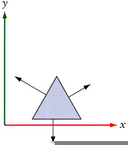
Figure 4.5: Surface normals prior to an affine transformation.
If we apply a general transformation matrix to this shape and the normals as well, we'll get the shape shown in Figure 4.6.
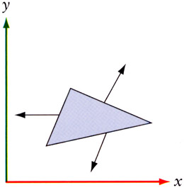
Figure 4.6: Surface normals following an affine transformation.
Although the shape may be what we desired, you can clearly see that the normals no longer represent what they are supposed to—they are no longer perpendicular to the surface and are no longer of unit length. You could recalculate the normals, but since we just applied a transformation matrix to our vertices, it seems reasonable that we should be able to perform a similar operation to our normals that correctly orients them with the surface while preserving their unit length.
If you're interested in the math, you can look it up [TURKOWSKI 1990]. But basically, it comes down to the following observations. When you transform an object, you'll be using one of these types of transformations.
-
Orthogonal transformation (rotations and translations): This tends to be the most general case since most objects aren't scaled. In this case, the normals can be transformed by the same matrix as used for vertices. Without any scaling in it, the transpose of a matrix is the same as its inverse, and the transpose is easier to calculate, so in this case, you'd generally use the transpose as a faster-to-calculate replacement for the inverse.
-
Isotropic transformation (scaling): In this case, the normals need to be transformed by the inverse scaling factor. If you scale your objects only at load time, then an optimization would be to scale the normals after the initial scaling.
-
Affine transformation (any other you'll probably create): In this case, you'll need to transform the normals by the transpose of the inverse of the transformation matrix. You'll need to calculate the inverse matrix for your vertices, so this is just an additional step of taking the transpose of this matrix.
In fact, you can get away with computing just the transpose of the adjoint of the upper 3 × 3 matrix of the transformation matrix [RTR 2002].
So, in summary,
-
If the world/model transformations consist of only rotations and translations, then you can use the same matrix to transform the normals.
-
If there are uniform scalings in the world/model matrix, then the normals will have to be renormalized after the transformation.
-
If there are nonuniform scalings, then the normals will have to be transformed by the transpose of the inverse of the matrix used to transform the geometry.
If you know that your WVP matrix is orthogonal, then you can use that matrix on the normal, and you don't have to renormalize the normal.
// a vertex shader for orthogonal transformation matrices // v0 -- position // v3 -- normal // c0-3 -- world/view/proj matrix // transform vertex to clip space dp4 oPos.x, v0, c0 dp4 oPos.y, v0, c1 dp4 oPos.z, v0, c2 dp4 oPos.w, v0, c3 // transform normal using same matrix dp3 r0.x, v3, c0 dp3 r0.y, v3, c1 dp3 r0.z, v3, c2
On the other hand, if you have any other kind of matrix, you'll have to provide the inverse transpose of the world matrix in a set of constant registers in addition to the WVP matrix. After you transform the normal vector, you'll have to renormalize it.
// a vertex shader for non-orthogonal // transformation matrices // v0 -- position // v3 -- normal // c0-3 -- world/view/proj matrix // c5-8 -- inverse/transpose world matrix // transform vertex to clip space dp4 oPos.x, v0, c0 dp4 oPos.y, v0, c1 dp4 oPos.z, v0, c2 dp4 oPos.w, v0, c3 // transform normal dp3 r0.x, v3, c5 dp3 r0.y, v3, c6 dp3 r0.z, v3, c7 // renormalize normal dp3 r0.w, r0, r0 rsq r0.w, r0.w mul r0, r0, r0.w
There are a series of macroinstructions (such as m4×4) that will expand into a series of dot product calls. These macros are there to make it easy for you to perform the matrix transformation into clip space. Do not make the mistake of using the same register for source and destination. If you do, the macro will happily expand into a series of dot product calls and modify the source register element by element for each dot product rather than preserving the original register.
Vertex Shader Registers and Variables
Shader registers are constructed as a vector of four IEEE 32-bit floating point numbers as illustrated in Figure 4.7.
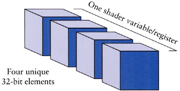
Figure 4.7: Vertex shader (and 2.0+ pixel shader) registers are made of four float vector elements.
While hardware manufacturers are free to implement their hardware as they see fit, there are some minimums that they have to meet. Since vertex shaders are going to be passed back into the pipeline, you can expect that the precision will match that of the input registers, namely, closely matching that of IEEE 32-bit float specification with the exceptions that some of the math error propagation rules (NAN, INF, etc.) are simplified. On those output registers that are clamped to a specific range, the clamping does not occur till the shader is finished. Note that you'll get very familiar behavior from vertex shader math, which can lull you into a sense of security when you start dealing with the more limited math precision of pixel shaders, so be careful!
|
|
EAN: 2147483647
Pages: 104
- Chapter I e-Search: A Conceptual Framework of Online Consumer Behavior
- Chapter IX Extrinsic Plus Intrinsic Human Factors Influencing the Web Usage
- Chapter X Converting Browsers to Buyers: Key Considerations in Designing Business-to-Consumer Web Sites
- Chapter XIV Product Catalog and Shopping Cart Effective Design
- Chapter XV Customer Trust in Online Commerce