2.9 Computer systems support software architecture
|
| < Free Open Study > |
|
2.9 Computer systems support software architecture
A computer systems-based application requires services and cooperative support from a collection of computer hardware and software to perform its designated function. The application requires a computational platform consisting of a CPU, memory, and secondary data storage, as well as a supporting operational infrastructure consisting of an operating system, database management system, network management, and additional process and resource management components. To understand how a computer-based application utilizes these components we must first understand the operation of these software infrastructure elements.
The central processing unit (CPU) and the main memory make up the basic computational engine and support the execution of all software within this computer. The CPU is composed of a collection of registers, computational subunits, data paths, and status registers that are used to move data about and to perform basic manipulations on these data (Figure 2.17). For example, a CPU can add, subtract, multiply, divide, and compare values or simply move them from one location to another. These are basic operations, which the remainder of the system's infrastructure is built upon and where it resides. The CPU also includes some additional support hardware, such as timers, interrupt registers and latches, input and output registers, and interconnections. For additional details on these elements refer to previous sections in this chapter.
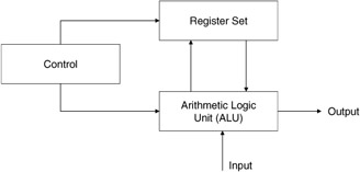
Figure 2.17: Computational engine.
In addition to the CPU, the other primary element within the basic system is the memory. A memory hierarchy is typically comprised of high-speed data registers, fast cache memory, primary memory, and secondary storage (Figure 2.18). The memory hierarchy at the closest point to the CPU hardware is populated with very expensive and limited high-speed registers. These registers are used to move a very limited number of data items into and out of the CPU for actual processing. The second level of the hierarchy is the cache memory. A cache memory is a bank of high-speed memory organized in a manner that allows for rapid retrieval of data; it executes at nearly the speed of on-chip or CPU registers. A cache memory is used to keep data most likely to be used next in close proximity to the CPU and in fast storage. The problem with cache memory and registers is that they are very expensive, thereby limiting the amount of either that may be found in an architecture. This type of storage hardware requires additional infrastructure support from the operating system and hardware to maintain the most appropriate piece of data in the most appropriate level of the hierarchy.
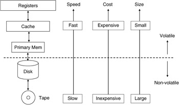
Figure 2.18: Memory hierarchy.
This control has typically been performed by a memory management hardware and software combination that uses locality of reference and locality of use principles to determine what information to place into the appropriate storage level and what information to remove.
The third element of the memory hierarchy is the primary memory. The primary memory in most machines today is sized in the hundreds of megabytes of storage range. This volume of storage allows for large portions of a data processing task to be memory resident during processing for small data processing applications. This is not to say that there is no swapping of information between the primary memory and the bulk secondary storage disk units. The volume of storage on such units is now in the order of tens of gigabytes range. The main emphasis in a computer system is on how and what performs the management of this hierarchy. The system's memory manager could do the best job for the typical application, but at a cost to all other high-performance applications of the operating system.
For the collection of computer hardware elements described previously, a working computer system requires policies and mechanisms for control of these resources and coordination between them to exist. This has typically been the function of a computer's operating system. An operating system consists of specialized software with hardware support to manage the interaction of the CPU and all other hardware elements supporting applications software running on the computer system.
2.9.1 Operating systems architecture
An operating system is computer software that interacts at a low level with the computer system's hardware to manage the sharing of the computer's resources among various software applications. An operating system runs as the most privileged of software elements on the system and requires basic hardware support for interrupts and timers to effect control over executing programs. An operating system typically provides the following services:
-
Hardware management (interrupt handling, timer management)
-
Interprocess synchronization and communications
-
Process management
-
Resource allocation (scheduling, dispatching)
-
Storage management and access (I/O)
-
Memory management
-
File management
-
Protection of system and user resources
-
Interprocess communications management
-
Network management
An operating system begins with the management of a computer system's hardware. Hardware management requires the ability to set limits on the holding of resources and the ability to transfer control from an executing program back to the operating system. These functions are realized through the use of hardware timers and interrupt services. A hardware timer is a counter that can be set to a specific count (time period). When the time expires, an interrupt signal is released, which stops the processor, saves the processor's state (saves all active register contents, ALU registers, status registers, stack pointers, program counters, instruction registers, etc.), and turns control over to an interrupt service routine. The interrupt service routine examines the contents of predefined registers (e.g., the CPU status register or a predefined interrupt register) or set memory locations and determines what operations are to be performed next. Typically, control is immediately turned over to the operating system's kernel for servicing of the interrupt.
Interrupt management and semaphores
The use of interrupts is one means for an operating system to effect control over the hardware of the system. Another means is through the use of cooperative software and control actions or instructions. The concept described here is mutual exclusion. An operating system, to guarantee singular, noninterfering access to a resource, must have a means to limit the access to a resource or a resource allocation mechanism via some mutually exclusive operator. A mutual exclusion primitive must possess the ability to limit access to a region or resource by only one element at a time, even when concurrent access is being attempted (atomic action). The all-or-nothing operation of an atomic function is required for the guaranteed, nonconflicting access and control over system resources by the operating system. A specific hardware instruction called test and set is provided in many computer systems to support this mutual exclusion primitive. The instruction in a single atomic instruction cycle reads a variable specified, tests its value against some basic value, and sets the variable to a new value if the condition tested for is valid.
The test-and-set instruction forms the basis for constructing semaphores. A semaphore is a system variable that can exist in only one of two states, either true or false, with no other valid states holding for the variable. The semaphore variables have atomic operations that can be performed on them, with no other operations outside of these being valid operations. The valid operations are of two types. The first operation is a request to set the variable, sometimes referred to as P(S). The second operation is a request to reset the variable and is sometimes referred to as V(S). These act much like a flip-flop in a logic circuit. The flip-flop can be set or reset, holding a zero or one value only. The set and reset operations of a semaphore variable are used to construct lock and unlock operations on resources or to hold and release operations on the resources. Semaphores are used to construct monitors, which encase the control of an operating system's controlled resource. For example, a monitor could be used as a means to limit the access to a tape unit to one process at a time by constructing a queue of waiting processes and one service routine. The operation would be to build an outside shell around the tape service routine to allow only one process access to it at a time. The P and V operators can be used for this function.
| (2.13) | 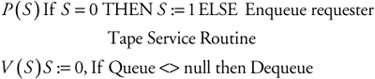 |
The processes that wish to use the tape service routine request service by first requesting the set function P(S). If no process is presently using the tape, then the S variable is zero. If it is free, the variable gets set, and the process is allowed to enter the critical section of code reserved for the tape service routine and use the routine. If the tape routine is already being used (indicated by the S semaphore variable being set to one), the request is enqueued, awaiting the release of the resource. Once a process finishes with the tape service routine, the V(S) or reset operation is requested. The reset operator resets the value of the semaphore back to zero and tests the queue of waiting processes to see if any processes still require service. If there are waiting processes, the top of the queue is removed and a P(S) request is issued for the process, starting over the entire process.
In this manner, using semaphores, complex monitors can be constructed to control access to a variety of system hardware and software resources. Monitors and semaphores have been used as a means to construct synchronization mechanisms to coordinate the actions of cooperating resources. For example, using the simple P and V semaphores described, one could construct two cooperative resource management routines by using three semaphore variables and the P and V operators, as follows:
| (2.14) | 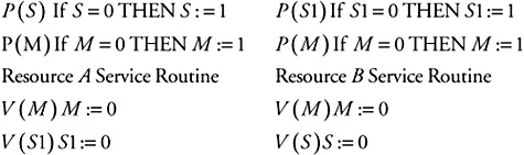 |
The two semaphores (S and S1) would provide for the synchronous operation of the two resources in such a way that they would toggle back and forth-either the resource A service routine first followed by the resource B service routine or the resource B service routine followed by the resource A routine. They could not, however, be executed concurrently due to the use of the M semaphore. One can see from this example some of the rudimentary needs of the database management system's functions being implemented using similar concepts to guarantee mutual restricted access to database-stored information and management routines.
Process management
A process is typically viewed as the lowest executable level of software recognized by the operating system. Processes can have additional internal management layers that are outside the domain of the operating system. The process does not, however, equate to a user program. A user program may be partitioned into multiple processes, or it could be a single process. The process does not have to be a fixed-size image in the system. It can take a variety of shapes and forms. The important aspect of a process is that there is a measurable entity that the operating system knows about and has information about, at least in terms of how this process interacts with and fits into the resources being managed.
Process management performs the task of managing software processes on a computer system. The operating system provides the services to create a process (build and populate a process control block for a new process), to kill a process (remove its process control block), to fork a process into tasks, to join tasks, and to dispatch processes. A process is described in the operating system using a process control block, or PCB. The PCB is created for a process upon its initial instantiation in the system. A typical process control block contains information such as a process identifier; a process type (user, system, database, network, etc.); process priority; process state information; process resource requirements (memory, disks, peripherals, other processes, etc.); and the state of required resources, process size, and present process memory load location. This is only a representative set of information and is by no means complete.
The operating system uses the process control block information from all processes within the system to coordinate the execution of all of the processes in order to meet some operating system's goal, such as fair execution, equal execution times, or some minimum average execution time. Processes run at a variety of levels within the operating system. Some processes are privileged and can, therefore, access protected regions of memory or hidden routines. Application processes may have no outside access other than the programmer's immediate load image. Others, such as the database management system, have some form of access rights in-between these two extremes. Processes exist within the system in many different degrees of completion, called states. A process within the system can be in one of these four states: ready to run, running, suspended or blocked, and terminated or dead (Figure 2.19).
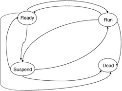
Figure 2.19: Process states.
The ready state refers to the state a process is in when it is prepared to run on the hardware but is awaiting the go-ahead from the operating system. To be in this state the process must have all the resources it requires to run allocated or at least fully specified, and it must have a known state for the resources stored in the PCB. Transitions from the ready state include terminate, dispatch, or block.
Terminating the process can be the result of a user action to kill the process or a command from another process, such as an operating system command, due to resource removal or an error condition (e.g., a bad control word for a printer). Dispatching a process moves a process from the ready state to the running state due to a scheduling action. The block transition moves a process from the ready state to the waiting state and is due to the removal of an acquired resource by the operating system or to some other deficiency that will not allow the process to go forward.
The running state refers to the point when the process has control of the CPU and is executing its instructions on the bare machine. The process has control of the hardware at this level and is only removed from execution by an interrupt from the operating system or an error condition. Transitions to this state only occur under control of the operating system and are due to scheduling actions. Transitions out of this state are due to a variety of conditions. A process can go from the running state to the termination state upon completion of execution, or a process can go back to the waiting state due to an input/output request (which is serviced by another process) or to the ready state due to an interrupt from the operating system for some other condition.
The waiting or suspended state for a process is used to hold processes that have not acquired the needed resources to execute or that have been removed from active execution due to some blocking action. A waiting action could be due to the transfer of data from the disk into memory or the completion of a cooperating process. Transitions to the waiting state are typically caused by requests for added resources, the removal or reallocation of some needed resources waiting for a cooperating process to finish its service, or waiting for resources to be freed up for other requests.
The termination or dead state is the state from which all processes originate and finally return to for exiting the system. This state is where a process is originally given basic assets, such as a process control block, initial memory load space, and so forth. In addition, this is the state where processes that have been terminated for whatever reason are returned. The functions here deallocate held resources and remove the process from the system.
Processes are moved from state to state based on the actions of various operating system support routines, such as the scheduler, dispatcher, and allocation routines. These routines have the job of determining when to move a process from one state to another, which process to move from one state to another, how to move the process, and where to move it. All these decisions are based on the interpretation of the operating system's managed process control block and the state of the system resources.
To determine which one of a set of ready processes to move from the ready state to the running state requires a scheduling policy and supporting mechanism to implement this policy. Originally computer systems used simple FIFO scheduling, where the next process in a list (queue, linked list, or some other data structure of PCBs) is the process scheduled for transition from the ready state to the running state. Other scheduling techniques try to be more fair and break up running processes into chunks of time called quantums. One such scheduler is the round-robin technique, where processes are moved from running to blocked or suspended states once they exceed their allotted quantum of time (a time slice or period). Suspended processes are placed on the circular queue, where they wait until they move around to the front of the queue to once again receive service. In this manner the CPU time is shared equally among all active processes (Figure 2.20). This type of scheduling is typical of a time-share system.
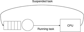
Figure 2.20: Process flow in a round-robin scheduler.
There are other techniques where the quantum time is not equal and where the selection process does not simply choose the next in line. The time slices are broken up into varying levels with the top level being short, small time slices; the intermediate being longer slices, but with also a longer wait time between getting service; and, finally, a long-term scheduler, where there is a greater time slice allocated but where the time between service intervals is even greater (Figure 2.21).
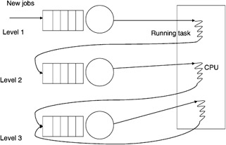
Figure 2.21: Multilevel time-slice scheduling.
A variety of other schedulers have been constructed for almost every conceivable measurable system quantity. For example, schedulers have been constructed that use priority (from a few levels to thousands of levels), execution time remaining, fixed deadline time scheduling, priority ceiling, and other techniques to select which process will get serviced next.
Once a process has been scheduled for service, it still must be moved from the inactive process control block state to a state where it is being prepared to execute upon the hardware. The task of preparing the process for actual execution falls on the operating system dispatcher. The dispatcher accepts the given process control block from the scheduler and proceeds to perform tasks required to ready the CPU for execution of the provided process. The dispatcher loads the stored CPU register values for the process into the appropriate registers and restores the CPU status registers. The stored program counter for the process is loaded into the CPU's program counter register, and the proper physical addressing information for the process is loaded into the appropriate memory-addressing registers and data structures. Once all of the parameters are in place, the dispatcher turns over control to the process by making the program counter for the process the next jump address from which to acquire the following instruction. The dispatcher may also have the task of resetting timers and interrupt flags before it turns over execution control of the CPU. The setting of interrupt timers is essential if the operating system is to reacquire control of the CPU at a later time.
Another operating system function responsible for the movement of processes from one state to another state is the memory allocation service. This will be discussed in more detail later in this chapter. Additional features that the operating system must provide for process management include error management and deadlock detection, both of which are also important to a database management system but not in the form used in an operating system. The error management services provide functions to detect, correct, avoid, and prevent errors, depending on the class of service required and the price the operating system and serviced applications are willing to pay.
Deadlock detection is performed for the processes and for the resources required by the processes running in the system. Deadlock occurs when one process is holding a resource another requires and a resource this process needs is held by the other (Figure 2.22). Deadlock management can take many forms. We may wish to detect deadlock and correct it by removing some of the offenders. We may wish to prevent deadlock from occurring by guaranteeing ahead of time that the allocation of requested resources cannot result in a deadlock. One way to realize this is to preallocate all of the resources needed for an executing process before it is allowed to begin. This is a safe algorithm but one that has an enormous amount of built-in holding time on resources and one that will directly result in longer waiting time by processes, resulting in longer overall execution times and lower system process throughput. Another means to deadlock management is to avoid deadlock altogether. Avoidance can be achieved by setting up resources in a specific order of access, which must be followed by all processes. In this way processes can only access resources in order and cannot hold a resource held by another that you are waiting for. The circular wait is removed in this approach.
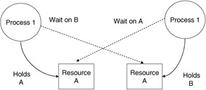
Figure 2.22: A deadlock.
Resource management
Resource management requires that the operating system coordinate the access and transmission of information from resources connected to the computer. Typical of functions handled by the resource management function of the operating system are memory management, peripheral device initialization, device setup, control over the data transfer, and closing of the peripheral device. In early systems the operating system controlled these devices down to a low level. In more modern systems the operating system sets up the parameters of a transfer and leaves the details of the data transfer to the device controllers and to direct memory transfer control devices. This leaves the operating system and CPU free to do other required resource management tasks.
Memory management
An operating system's storage manager manages the memory hierarchy of the computer. The operating system in particular must coordinate the movement of information into and out of the computer's primary memory, as well as the maintenance of the memory's free space. To perform these functions an operating system typically uses a scheme where the primary memory is broken up into fixed-size pieces called pages or variable-sized pieces called segments. The operating system then manages the movement of pages or segments in memory based on policies in use. The memory manager must allocate space for processes upon initiation, deallocate space when a process completes, and periodically clean up the memory space when the memory becomes fragmented due to allocation and deallocation of uneven partitions. The memory allocation problem is directly tied to the memory map. (See Figure 2.23.)
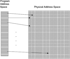
Figure 2.23: Memory map.
The memory map indicates which areas in memory are allocated to a process and which areas are free to be allocated to a new process. This memory map can be managed in a variety of ways to help the allocation manager. The list of free areas can be organized into a free list, where the blocks are structured as a tree of increasing block size, or as a heap, with the largest block always toward the top of the heap. Memory allocation then becomes a function of selecting a block of appropriate size based on the selection policy in place. Some policies include first fit, where the first block encountered that fits this process is selected. Another policy is best fit, where the blocks are scanned until one is found that best fits the size of the process to be loaded into the memory. There are numerous other schemes, but they are beyond the scope of this chapter.
Hand in hand with allocation is deallocation of memory. As pages or segments are released by processes leaving the running state, they must be removed from the allocated list and replaced into the free list of free pages or segments. The deallocated segments are restored to the list in a block equal to the size of the allocated process that held them. These free segments are then placed into the free list in a location appropriate to the size of the free segments being restored.
However, not all replacements are done in such a nice manner on process execution boundaries. Most are performed on a full or near-full primary memory. In order to still allow processes to move forward in their execution, we must reorder the active pages by some policy that will allow us to remove some active pages and let them be reallocated to other more demanding or starved-out processes. The most common page replacement algorithm and deallocation policy is based on the least recently used (LRU) principle. This principle indicates that the least recently used page is most likely to stay that way for the foreseeable future and, therefore, is a prime candidate to be removed and replaced by a waiting process. Other schemes used for page replacement include most recently used, least frequently used, and random removal. All of these policies have been examined in detail in the past and have merits for certain process activities, although for database systems some of these are downright disastrous. The database process acts in a way that is not typical of most applications and, therefore, will not react the same to a certain policy.
Another job for memory management is to maintain a map of free memory areas and to periodically clean up memory to free up larger contiguous chunks to make allocation easier. This process is called garbage collection and reallocation. The allocation and deallocation policies discussed previously result in memory becoming periodically fragmented. When memory is fragmented into very fine fragments, it may become impossible to find contiguous blocks of free memory to allocate to incoming processes (Figure 2.24). To rectify this problem, memory management services periodically check the map of memory to determine if cleaning up the loose fragmented free blocks into larger segments will result in significant increases in free contiguous blocks of sufficient size.
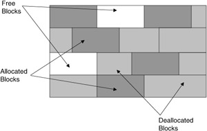
Figure 2.24: Fragmented memory.
One technique scans all marked free blocks and coalesces adjacent holes into marked, larger free segments. These are then added to the free list with the coalesced disjoint holes removed from the free list (Figure 2.25).
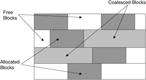
Figure 2.25: Marking free blocks in memory.
This in itself may not result in sufficient free space of adequate size. To get larger free blocks it may be necessary to periodically scan the entire memory and reallocate where processes are stored to clean up the memory allocation map into two areas-one a contiguous area consisting of all allocated memory blocks and the other all free memory blocks. The process by which all allocated blocks are moved and reallocated to one end of memory is called compaction, and the process for reallocating all of the newly freed space into the free list is referred to as garbage collection (Figure 2.26). As with a garbage truck, compaction strives to compress the contents into one end of the container, freeing up the remainder of the space for more garbage. The process requires the reallocation and movement of processes and their addresses (all references must be changed in PCB and physical load segments).
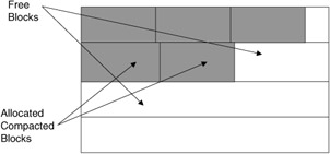
Figure 2.26: Memory after garbage collection.
Beyond these basic memory management schemes some operating systems, along with support hardware and software, support both paging and segmentation. In this scheme the memory is decomposed into segments. A segment has some number of pages, and a page is of a fixed size. The segments are mapped into and out of memory as pages were in the first scheme (see Figure 2.27).
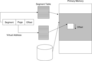
Figure 2.27: Memory with both paging and segmentation.
File management
File management is a function of the operating system that controls the structure and storage of information on nonprimary storage resources. A typical application of file management is the files stored on a disk drive or tape drive. Files are collections of data and/or programs that are moved to or from memory. To perform this movement requires that the file's structure, format, and location be known to the operating system. The file manager uses this information to request memory space from the memory manager to move a file from storage into the memory. When ready to move back into storage, the file system uses information from the memory manager to determine if any changes have been made to the file. If no changes have been made, then the file can simply be discarded. If changes have been made, the file manager needs to determine if more space than the file originally occupied is required. If it is, the file is possibly stored in a different location or requires fragmentation on the device. Similar to the memory manager, the file manager may periodically be required to reallocate storage space and move files to free up larger contiguous areas.
The file manager provides additional services to the applications. File management provides functions to create, delete, and insert information into files; append information to the end of a file; and alter the contents of a file. File control mechanisms support the sharing of files among users in order to control the form of access allowed, to structure files for optimal space and time use, to name or rename files, and to copy and replicate files as needed for system support.
Management of the location and contents of a file system is controlled by the use of a file directory service. A file directory can be used as the means to facilitate access to files and to limit the use of a file as specified by the owner or the operating system. Some file managers organize files by type, such as .EXE for executables, .TXT for text files, .FOR for FORTRAN files, .PAS for Pascal files, and .C for C files. To aid in the management of files the file manager maintains a file control block with information about the files under its control. This information can facilitate the maintenance and use of the files.
Protection
Protection is an operating system function that manages access to controlled resources. Protection typically consists of access authorization, access authentication, and access restrictions. The operating system checks the authorization rights of a service requester before the service is performed. If the proper rights exist, the access is allowed; if not, the requester is blocked from access.
Access authorization is a process through which the operating system determines that a process has the right to execute on this system. The most common form of this control is the user name, which we are all familiar with when we log on to a computer. The second form of operating system protection is authentication. Authentication deals with the problem of a user being verified as to who he or she claims to be. The most common form of authentication is the password. The combination of user authorization through a stored user name and user authentication through a password has proven adequate for most noncritical computer systems' access restriction management. If necessary, these two methods can be applied to the access of any resource to limit access to it. The problem to be addressed is the degree of protection required and the amount of overhead we are willing to pay for it.
Access control is a more involved issue and deals with how to control the use of information and programs by users who have authorization to be on a system. To control who uses software on the system and how it is used, an operating system must provide mechanisms to limit the execution rights of controlled software. To do this operating systems use some form of access control. The most common are access control lists, access control matrixes, and capabilities. Access control lists provide a means to list all software elements to be controlled in the system and provide a list of users or processes that have the right to use these software elements. The control can also limit the type of execution rights the process or user may have. For example, we may only allow for the invocation of a process, not the freeing of the CPU to the calling process. We may allow only read access to a region of a software process or insert rights, or we may give unrestricted rights. The main mechanism (the comparison of a user identifier against a list of rights) for an access control list is performed in a centralized site, possibly within a separate operating system service or within the controlled software itself. Capabilities perform a similar function but do it in a distributed fashion. Capabilities are created for each controlled element and are requested by processes that wish to use the controlled element. If the capability is appropriate for a process, it is given to the process. The process can then use the capability like a ticket to access and use the controlled element.
Peripheral device management
Input/output and peripheral device management services were created to remove the physical details of use from user processes and to provide for more seamless and fair management of the resources. The goal of peripheral device management services is to make access clear, clean, and transparent to users. Management should remove all physical dependencies from users' access requirements and replace these with logical mechanisms that are already common in programming environments. The control is to make access device independent. The user should not have to know what type of device or where the device is located to access data or service software.
Management for peripheral devices is bound into two classes of operating systems service routines: I/O and device managers. The operating system strives to make all accesses appear the same. The typical method is to make all accesses have the look and feel of a file access. The I/O management process has the function to set up and maintain the logical channels or paths between CPU-resident processes and the outside world. The functions provided by this element include channel allocation and deallocation, channel setup, channel coordination, and remote data transfer and control. Included in this may be error detection and correction over the channel. In concert with this function is the device management function. Device management services provide mechanisms to perform device-dependent setup, allocation, control, synchronization, deallocation, and data transfer.
I/O and device management create the physical link and control the transfer. Included in this function is the request for buffer assets for the channel to utilize in transferring information from the secondary storage to the internal computer's memory. The buffers are used as the intermediary between the devices and the CPU. They allow for the concurrent operation of the I/O with applications processing within the system. The I/O channel control and device control are typically handled in an operating system as an independent process. The operating system initiates the I/O or device operation and departs, allowing the device and I/O managers to perform the task and, when completed, interrupt the operating system to indicate the completion of the task. The interrupt can be active, where it stops the operating system for immediate service, or it can be message oriented, where it sets some status indicator, which the operating system will check at its leisure.
When integrated with the operating system's file manager, these routines form a seamless link between the stored programs, data, and the run-time system. The file manager is used for the direct access of logical storage elements by the operating system and controlled processes. The file manager provides services to name files, address files, control access, select and coordinate access paths, perform background copying and backup for recovery, coordinate the allocation and deallocation of resources where file information is located, and manage the placement (logical) of stored information. An important function of the file management system is lock management. File managers create, issue, and control the locking and unlocking of files and records within files. This service is extremely important for concurrency control.
2.9.2 Network control software
Network management software manages the sending and receiving of information over a communications medium. Typical functions include message routing, naming, addressing, protection, media access, error detection and correction, communications setup, and management.
Routing is a system network management function needed to coordinate the movement of information over a network(s). In a local area network this function is not needed in all cases. Routing may simply require sending the data in a certain direction over the medium, or it may require more elaborate policies for selecting a channel or wire to send the message, based on the sender's location and network traffic. Routing is a required function in wide area networks such as the Internet.
Naming is required to facilitate the transparent access to all system resources, local or remote. A naming scheme should have the following features: provide for sharing of objects, provide access to replicants, and provide fully transparent access. The naming function must support two types of names for each item managed: an internal (systems) name and en external (user) name. The naming function must manage the translation and management of the external names with internal (unique) names.
Addressing is the means through which the system determines where a named item is located. Addressing schemes may be broken up into hierarchies, where local computers have their own set of names, which may not be unique between systems. The combination of the system's address (a node on the network) and the local name is sufficient to provide a system's unique name. Likewise, we could have a unique name and address for each network in a collection of interconnected networks.
Access control over a network deals with policies and mechanisms to limit the mode of access given to network users. Access limitations could be as simple as login privilege or more complex, such as limiting the type of connections one can acquire or the type of access to remote information. The mechanism for limiting access may be embedded in software accessing the network or may be explicitly provided by the user of the software accessing the network.
Protection is a function of the operating system that deals with the management of resources from malicious or accidental access that may deadlock the system. There are two major classes of protection schemes: The first tries to avoid the problem by preallocating resources; the second allows deadlock to occur but provides means to detect and correct problems. Avoidance builds access to resources in a methodical fashion. One scheme requires a process to acquire all resources it will need ahead of time and hold them for the duration of its access. This is highly restrictive and may cause excessive delays for other resources that may need the held resources. Deadlock detection allows for more concurrent access of resources but at the cost of potential deadlocks. One scheme requires the construction of waits-for graphs, which allow for the detection of potential and actual deadlocks and provides mechanisms to remove deadlock by aborting conflicting processes.
One can see from this simple description the possible problems from a database's perspective. The operating system may limit the sharing of resources between processes, even if the database would allow it. Media access software controls the interaction of users and software processes with the network. Typical mechanisms deal with the recognition and login interaction with a network node. Media access software deals with the connection to the communications medium and the setup of communications sessions. Access allows a process to log in with the network and be recognized by others over the network.
Communications setup and management act in conjunction with media access software to interact with remote nodes and set up a link. Typically, one node requests a linkup with a remote node. If the remote node can support an additional session, it creates a control block to hold information about the setup. The requesting node is signaled that a session was successfully created. Once created the interacting processes can send and receive information using their preallocated parameters.
Client/server policies and mechanisms
The client/server mode of remote resource access and control is commonplace. One just has to open up a trade magazine to find advertisements for systems claiming client/server processing. The technique provides some of the benefits of distributed systems but without the added control overhead. Client/server participants operate by requesting and receiving services as needed. Servers hold resources and can provide service to clients. Clients require held resources and can request service from the server. The server grants service to the clients based on the present use and the sharing policy in place at the server. The methodology does not offer the tight synchronization one would find with distributed systems, but it does offer a simple means to access and share remote resources in a uniform fashion. Its simplicity has added to its popularity and growth.
Remote procedure call policies and mechanisms
A similar remote access mechanism is the remote procedure call mechanism. As with local procedures, a requester must know the procedure's name and the proper parameters. The requester calls the remote procedure and the blocks awaiting the remote procedure's response. The called procedure performs the requested service, and, on return of control to the caller, the caller unblocks and continues processing. The procedure is exactly the same as the conventional procedure call except that the call is over a remote channel to another site. Further details of network software and specifics related to databases will be described in later chapters.
2.9.3 Fault detection and recovery
An operating system has a requirement to monitor the system for errors, faults, and failures and to provide mechanisms to correct these conditions or to reconfigure around them. To detect errors or faults in the first place an operating system uses a few basic functions. The first relies on hardware detection of errors-for example, parity check bits, cyclic redundancy checks, and computational checks such as overflows and divide by zero. These provide for detection of intermittent or hard errors within the communications and computational infrastructure of the machine. To check for more subtle or buried errors requires the periodic initiation of fault-monitoring software. This software collects information from these basic hardware elements and from running software using predefined test points. These collected data are then periodically analyzed for patterns that may indicate software or hardware errors present in the system. This software is referred to as program-monitoring software.
Once an error condition has been detected using the operating system's error-monitoring mechanisms, the next job is to determine where the error is coming from and then to isolate the error down to some predetermined hardware or software granularity-for example, for hardware down to a replaceable board or a component such as an integrated circuit; for software down to a module, process, function, or possibly a block or line of code; for data within the file, down to the record or data item level. The level of isolation provided will depend on the overhead and price the system is willing to pay for the detection and isolation. This mechanism is typically called fault localization. Fault localization operates by using known test drivers and known responses to walk through system hardware and software elements testing for erroneous outputs. It is not, however, sufficient to simply detect an erroneous output condition and assume this is the component at fault. Errors can propagate through numerous layers of hardware and software, only showing up in later stages. The goal of fault localization is to detect an error, and then test back through all interacting elements to isolate the fault or error to the appropriate culprit.
On isolation of a faulty hardware or software element, the operating system must determine an appropriate action to relieve the system of the error. The process of performing this function is called recovery and reconfiguration. The most common method is to perform some recovery action first. The recovery may be as simple as reload and restart or just resetting the already loaded software. More elaborate techniques include maintaining partial execution history (register status, computation state) and to reset and restart from some intermediary point in the software. If an error is more elaborate, it may require the removal and replacement of the software or hardware element to effect recovery.
If redundant hardware and software are available, the recovery can take on a more global perspective. Recovery can look to other assets available within the system to work around the errors or failures. This form of recovery requires the reallocation of resources (both hardware and software) to fill the gap left by the failed elements. This form of recovery is referred to as reconfiguration. Reconfiguration will be discussed in further detail in later chapters.
2.9.4 Database management systems
A database management system is composed of five elements: computer hardware, software, data, people (users), and operations procedures. The computer hardware consists of processing elements, volatile memory, secondary storage components, archival storage devices, input and output devices, and possibly specialized computational devices and input sensors. The software for a database can be broken up into three categories: infrastructure support software, database software, and applications software. The infrastructure support software includes the operating system and network communications software. The database management system software includes components for storage management, concurrency control, transaction processing, database manipulation interface, database definition interface, and database control interface. Applications software is dependent on user needs. Data are the commodity the database system is managing. People and applications programs, as users, manipulate the stored data and, as database administrators, examine and maintain the database for the users. Operations procedures are developed and put into practice to provide additional support to the database system. Operations procedures include backing up the database onto nonvolatile mass storage, such as tapes, on a scheduled basis, and collection of operational statistics for use in tuning the database's structure and performance.
A database management system performs as an applications process under the control of the operating system. The database manager uses the operating system's file management and memory management services to store and retrieve the data in the database. Interface to the database management system is through three distinct paths: the database definition language, database manipulation language, and database control language.
Database definition language
A database is constructed to manage data that must be maintained for future use. The data in the database are organized into structured collections based on applications' informational needs. Data are placed in the database in these predefined data structures. These data structures are defined using data definition primitives within the database's language. Data definition primitives allow the database designer to specify individual data item composition as well as more complex data structures composed of these low-level data items.
A data item represents the smallest identifiable piece of information managed within the database. These data items, or attributes, are given a unique name, and their physical structure and type are specified using data types available within the given language. In the Structured Query Language (SQL) used to define relational databases, a data item is defined at the same time that a relation is defined. As an example, to define a person relation in SQL we could use the following code:
CREATE TABLE person (name VARCHAR(30) NOT NULL ssnum INT(9) NOT NULL, bdate DATE NOT NULL, saddr VARCHAR(20) NOT NULL, city VARCHAR(20) NOT NULL, state VARCHAR(20) NOT NULL, zcode INT(9) NOT NULL, PRIMARY KEY (ssnum))
This example defines a person data entity to be composed of seven distinct data items. Each data item is given an explicit data type and a maximum size for the data item-for example, the name can be from 1 to 30 characters long; the birthday is of type date. Date is defined in SQL as having the form year-month-day and is comprised of four integers for year and two integers for both the month and day entities.
Database definition typically uses a compilation process to build and generate the database schema or data description model. The database definition process results in descriptions of the database in both logical and physical terms and the generation of a mapping between the two, as shown in the following code segment:
CREATE TABLE customer (cname VARCHAR(10) NOT NULL, cnum INT(3) NOT NULL, credlim DECIMAL(6, 2), PRIMARY KEY (cnum)) CREATE TABLE order (onum DECIMAL(5) NOT NULL, cnum DECIMAL(3) NOT NULL, spnum SMALL INT NOT NULL, date DECIMAL(6), amount DECIMAL(6, 2), PRIMARY KEY (onum))
These data definition constructs are from the Structured Query Language (SQL) and specify two relations. One is a customer relation and the other is an order relation. The customer relation is specified as having three attributes: a customer name, a customer number, and a credit limit. The key attribute for the relation is defined as the customer number attribute. The second relation is a customer order relation. The customer order relation is composed of five attributes: order number, customer number, supplier part number, date of the order, and dollar amount for the order. The primary key for this relation is defined as the order number. Also notice that since the customer number in the order relation is the same as the customer number in the customer relation, this attribute constitutes a foreign key into the customer relation. By using techniques such as this the relations are linked together in an informational sense.
For all database models, there exists a language for the specification of the database's structure and content. The specification is called the schema design and represents the logical view of information that is to be managed by a particular database management system. The specification gives the designer the ability to map disjoint logical user views of information into a comprehensive global view of information and finally into a mapping to physical storage structures. This separation of the logical and physical database structures results in transparency from the physical and logical dependencies of the data from the users. By doing this the database designer has the ability to alter the physical storage structure and organization in order to optimize low-level storage and retrieval efficiency without the need to alter the logical user view and its application's code.
The database design language, beyond the basic ability to define data, must also have the ability to alter specified data structures and their physical representations after the database has been specified. Features to drop a structure from the database, to insert a new structure, or to alter an existing structure need to be built into the language for completeness and for the maintenance of a database. Keep in mind that most databases will not be constructed, put in service, and removed over a short period of time. When enterprises construct and populate a database, they do so continually over the lifetime of their system. The lifetime of a database system in such an enterprise may span decades, implying that growth and change are inevitable and must be designed for up front. A database within such an environment is initially specified and put into service. After using the database, some initial adjustments will be required. In addition, as the enterprise grows and possibly changes the focus of its activities, so must its information base change in order to stay competitive. One can see that a rigid, unchangeable specification and operational structure will lead to obsolescence and degradation of performance to the very applications the database was initially specified to support. A database specification language and implementation must be flexible in order to be useful and enduring.
Database manipulation language
The component of the database most visible and recognizable by database professionals, as well as applications developers and possibly applications users, is the data manipulation language. This component of the database can take on many forms, the most common being a programming language-like interface, which provides the ability to retrieve and store information within the database previously specified by the database design language.
The data manipulation language need not, however, take on a textual and procedural view only. The data manipulation language can be visual, as in the spatial data management system, where information is described using icons and is retrieved using pictures that can be zoomed in on for greater detail about an item-for example, given that we have a map of the United States used as the top-level view for the querying of business information, we may wish to find out what universities are within the southern region of Massachusetts closest to Cape Cod. We would first select the type of icons we wish depicted-for example, only show regions with universities by selecting the university icons. The visual display would then highlight cities where major universities are located. To isolate a particular university or to find out more about the area where a university is located, we begin by selecting the area, say southeastern New England around Cape Cod, by encircling the region. The display would then expand this area, again only depicting the universities. To select a particular university select a university icon (Figure 2.28). If we selected the University of Massachusetts at Dartmouth, we may next get an aerial view of the university. To discover more information we could select a building, then a department, or possibly even a particular professor or course offering. In such a way the majority of information needed could be extracted and displayed in visual form. There are, however, limitations with this method. Not all information lends itself to visual-only representation. We may be forced to place only a subset of the totally available information in such a system and use a separate database interface for more textual information.
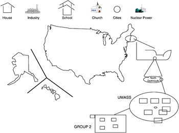
Figure 2.28: Spatial data management system.
A second type of interface is related more toward business uses of databases. This type of interface uses a company's typical paper forms for information about inventory, sales, employee records, and so forth as the interface presented to the users of the database. An application or user simply selects the proper form, say an employee record form, and selects which employee or group of employee records to look at by typing in information on the form.
Figure 2.29 shows a form that may be used by a business to represent customers or suppliers. The form shows the company's major information, such as the company's name, address, phone number, fax machine number, and e-mail address, and possibly some information about the type of product or service it produces or supplies. In addition, the form may include some extra fields, which can be used to aid in finding information. In the example screen of Figure 2.29, there is a separate field called Find on the bottom of the screen. In this field a user could input parameters to be looked for or qualifiers to aid in a search-for example, if we wished to select all companies in Boston, Massachusetts, that are stored in our database, there are two potential ways to do this. The first is to enter the names Boston and Massachusetts in the appropriate city and state fields and select Go on the bottom right of the screen. This would indicate to the database to match any records that have these qualities in these particular fields. To find additional entries with the same fields one would select the Next field on the lower-right corner. An additional means to recover the same records is to type All, Boston, and Massachusetts in the Find field of the form.
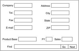
Figure 2.29: Sample form.
A third form of nontraditional data manipulation language is the query by example, or QBE, type of facility. In a query by example environment the user requests basic information about a record of interest-for example, a company name. The system then returns a template, which may or may not fit what is being requested. This template can then be used by the user to further refine the query and to receive additional examples to use in formulating a more precise query. The QBE interface developed for the relational model is closely tied to the forms-based interface. The examples come back in the form of tables, and the user fills in known quantities. The database then attempts to fill in a response table using this information as the restriction information.
Other data manipulation languages are based on functional evaluation. In these types of languages the users request information from the database through the use of function calls. The function calls may return text, graphics, video, sound, or a variety of data formats. The form returned is dependent on the data formats of the function called and the parameters' data types. This form of query interface is most prevalent in object-oriented databases and in multimedia and hypermedia databases. The information that is passed between the database and the applications is in the native form of the application, not in the base form of the database. This type of interface is desirable in applications where data come in nontextual forms that nevertheless are stored and managed by a database management system.
The most prevalent form of data manipulation language today is still by far the textual and procedural languages, such as Structured Query Language (SQL) and Object Query Language (OQL). In these languages the queries are formed much like a program in any programming language. The query writer has some reserved words that provide some given functionality. The typical query includes reserved words to select multiple records, a single record, or a subset of a record; to specify where the record is to come from; and any qualifiers on the access and retrieval of the requested information. In languages of this form the queries take on the structure and execution flow of the program-for example, if we are looking at a relation Order, of the form order number, order date, customer number, product ordered, quantity ordered, unit cost, total cost, and want to find all orders (the entire tuple) from the XYZ Company for bookbindings since May 1995, the following query could be used, given that the XYZ Company has the customer number I101:
Range of O is order; SELECT O.onum, O.odate, O.cnum, O.pname, O.qty, O.uic, O.ttl FROM Orders WHERE O.cnum := 'C101' and O.odate > '4-30-95' and O.pname := 'bindings';
In this query we first set an internal variable to range over all values of the search relation. Second, we request the search look to retrieve all the attributes of the relation Order in the same order in which they are stored. Third, we specify where to look for these attributes, namely in relation Order. And, finally, we restrict the selection to find and copy into our result relation only those tuples that have the company number attribute stored with the value of 'C101', the value for attribute order date greater than the end of April (odate > '4-30-95'), and only the parts named 'bindings'.
The procedural languages such as SQL also have operators to insert new tuples in the database, to create new relations, to modify existing relations, to delete relations, and to update the contents of a relation. An insert of a tuple into the previous relation could be readily performed by issuing the following instruction:
Range of 0 is order; INSERT INTO Orders VALUES ('0100', '5-21-95', 'C101', 'binding', '100', '1.25', '125.00') ; To delete the same tuple from the database requires that we first find the proper tuple, and then remove it from the relation. The code may appear as follows:
Range of 0 is order; DELETE FROM Orders Where O.cnum := '0100' AND O.odate := '5-21-95', AND O.cnum, := 'C101' AND O.pname := 'binding' AND O.qty := '100' AND O.uic := '1.25' AND O.ttl := '125.00';
A simpler means would be to refer to the intended tuple by its primary key only. Since in a relational database the primary key by definition must uniquely define a tuple in a relation, then this alone can be used to find and delete the proper tuple. The reformed deletion operation would be as follows:
Range of 0 is order; DELETE FROM Orders Where O.onum := '0100';
What the reader should realize from this discussion is that there is no one correct means of retrieving information from a database. There are, however, standard means [1]. The important concept is that database retrieval is different from conventional programming language processes. There is a language of informational access, which has evolved and continues to evolve along with database technology. These languages, however, will continue to be different from their programming language counterparts primarily due to the differences in the requirements for persistent data beyond the point of a program's existence and the requirements for consistency and correctness of information beyond the scope of any single process or program.
Database control language
The last component of the language interface to a database management system is the data control language. This is also sometimes included as part of the data definition language in some descriptions. We decompose it here to help focus on some of the differences. In particular this component of a database interface is typically used by the database administrator. Typical functions provided at this layer are tools to monitor database operations; restructure underlying physical storage; reset constraint values on data items; rename relations; create additional indexes; archive data; and to grant, alter, or revoke privileges. The typical interface at this level is textual oriented with specialized analysis tools used to analyze collected information.
The database administrator could, for example, examine a set of range constraints on an attribute value and determine, based on the user's requirements, to alter them to increase the possible domain of values considered correct by this attribute-for example, if the database administrator feels that there is not a sufficient range of values to represent the job categories in a company, he or she could elect to increase the number of jobs and their titles as needed. If originally there were only three titles in the company:
jobtitle IN {welding, management, sales} but it is determined that the data structure must be expanded to more fully meet the need of additional job categories, the data administrator simply extends the list of valid items. This instruction simply adds three new categories to the list of allowable job titles. These new titles can now be used by applications querying or modifying the database.
jobtitle IN (welding, management, metal cutter, machinist, glass cutter, sales)
Constraints for the range of values of a data item can be altered by increasing the values assigned to boundary values-for example, if an initial constraint indicates that the customer number ranges from 1 to 500, but we now find ourselves with 501 customers, the constraint must be altered to allow storage of the new customer record. To change the constraint, simply set RANGE OF Customer.cnum 1 ... 750. Constraints on when to perform testing functions can be altered also-for example, test constraints on reads, writes, or commit.
Beyond the alteration of constraints, database data control languages provide instructions and constructs to grant additional privileges to users or to revoke privileges. The GRANT statement is used to allow a user to perform certain manipulations-for example, to allow user Tom to read values from the Customer relation can be done by:
GRANT SELECT ON Customer TO Tom;
One could also grant the rights to multiple operations within one statement, as follows:
GRANT SELECT, UPDATE, INSERTION ON Customer TO Tom;
This statement grants selection, update, and insertion rights to the user Tom on the relation Customer. In this manner the database administrator can alter, add, or remove access rights to any items within the database. Not all database systems and models support a wide variety of data control language features. In several languages, many of these features would necessitate bringing the database off line for alteration.
|
| < Free Open Study > |
|
EAN: 2147483647
Pages: 136
- Chapter III Two Models of Online Patronage: Why Do Consumers Shop on the Internet?
- Chapter VI Web Site Quality and Usability in E-Commerce
- Chapter VIII Personalization Systems and Their Deployment as Web Site Interface Design Decisions
- Chapter XVII Internet Markets and E-Loyalty
- Chapter XVIII Web Systems Design, Litigation, and Online Consumer Behavior