2.3 CPU architectures
|
| < Free Open Study > |
|
2.3 CPU architectures
The central processing unit (CPU) is the brains of a computer system. The CPU consists of the arithmetic logic unit (ALU) and the control unit, as indicated previously. The ALU can come in a variety of configurations-from a single simple unit, shown in Figure 2.1, that performs simple adds, subtracts, increments, decrements, load, and store, up to extremely complex units that perform operations such as multiply, divide, exponentiation, sine, cosine, and so on. The primary operation of the ALU is to take zero or more operands and perform the function called for in the instruction. In addition to the ALU, the CPU consists of a set of registers to store operands and intermediate results and to maintain information used by the CPU to determine the state of its computations. There are registers for the status of the ALU's operation, for keeping count of the instruction to be performed next, to keep data flowing in from memory or out to memory, to maintain the instruction being executed, and for the location of operands being operated on by the CPU.
Each of these registers has a unique function within the CPU, and each is necessary for various classes of computer architectures. A typical minimal architecture for a CPU and its registers is shown in Figure 2.3. This architecture consists of a primary memory connected to the CPU via buses that use a memory address register and memory data register to address a location in memory and transfer the contents of the location from the memory into the memory data register or to transfer the contents of the memory data register into memory. There are registers in the CPU for instructions (the instruction or IR register), instruction operands, and results of operations; a location counter (which contains either the location in memory for instructions or operands, depending on the decoding of instructions); a program counter or PC (which maintains the location of the next instruction to perform); and status registers.
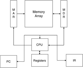
Figure 2.3: The CPU and its associated registers.
The CPU also contains the control unit. The control unit uses the status registers and instructions in the instruction register to determine what functions the CPU must perform on the registers, ALU, and data paths that make up the CPU. The basic operation of the CPU follows a simple loop (unless interrupts occur that alter the flow of execution). This loop is called the instruction execution cycle (Figure 2.4). There are six basic functions performed in the instruction loop: instruction fetch, instruction decode, operand effective address calculation, operand fetch, operation execution, and next address calculation.
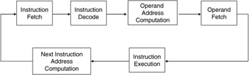
Figure 2.4: Instrumentation execution cycle.
Instruction fetch uses the program counter register to point to the next instruction stored in memory. The address is placed in the memory address register and the instruction is then gated (electronically signaled by the CPU control element to transfer the data) from the data memory into the memory data register. The instruction then flows into the instruction register under the direction of the control unit.
Once an instruction is in the instruction register, the second cycle in instruction execution can be performed-decode. To decode the instruction the control unit must recognize what type of instruction is being requested-for example, does the instruction require additional data from memory to perform its intended function, or does the instruction involve only ALU resident registers?
The third cycle within instruction execution is the operand effective address calculation. This phase of instruction execution operates by extracting operand address information from the instruction and then performing some form of calculation (e.g., base plus offset) with this information to form a physical address in memory. We will discuss the various types of addressing in later sections of this chapter. Once the type and number of operands are determined, the ALU can acquire the operands and then set up to perform the decoded instruction.
Once we have a physical address, we can fetch the operand (the fourth function of the instruction execution cycle). To fetch the operand the effective address is placed in the memory address register, and the control gates the contents pointed to by the memory address register into the memory data register. The extracted operand is then gated from the memory data register into an ALU register. If an additional operand is needed, the two cycle steps for operand fetch would be repeated to get the remaining operand. With all required operands in ALU registers the instruction requested can now be performed. The instruction execution is controlled by the CPU control unit. The control unit signals to the ALU to perform the instruction-for example, if an add is requested the ALU would add the A and B registers and place the result in the C register. After the instruction is completed the last step in the instruction execution cycle can proceed.
The next address calculation uses the program counter and/or any pertinent computation result (such as a go to-type instruction) to determine where in the memory the next instruction is to be found. The normal mode of address calculation is to increment the contents of the program counter. With the new address the instruction cycle begins once more.
This execution sequence represents the basic functions found in all computer systems. Variations in the number of steps are found based on the type and length of the instruction.
2.3.1 Instruction types
Based on the number of registers available and the configuration of these registers several types of instruction are possible-for example, if many registers are available, as would be the case in a stack computer, no address computations are needed and the instruction, therefore, can be much shorter both in format and execution time required. On the other hand, if there are no general registers and all computations are performed by memory movements of data, then instructions will be longer and require more time due to operand fetching and storage. The following are representative of instruction types:
0-address instructions-This type of instruction is found in machines where many general-purpose registers are available. This is the case in stack machines and in some reduced instruction set machines. Instructions of this type perform their function totally using registers. If we have three general registers, A, B, and C, a typical format would have the form:
(2.1) which indicates that the contents of registers B and C have the operator (such as add, subtract, multiply, etc.) performed on them, with the result stored in general register C. Similarly, we could describe instructions that use just one or two registers as follows:
(2.2) or
(2.3) which represents two-register and one-register instructions, respectively. In the two-register case one of the operand registers is also used as the result register. In the single-register case the operand register is also the result register. The increment instruction is an example of one-register instruction. This type of instruction is found in all machines.
1-address instructions-In this type of instruction a single memory address is found in the instruction. If another operand is used, it is typically an accumulator or the top of a stack in a stack computer. The typical format of these instructions has the form:
(2.4) where the contents of the named memory address have the named operator performed on them in conjunction with an implied special register. An example of such an instruction could be as follows:
(2.5) or
(2.6) which moves the contents of memory location 100 into the ALU's accumulator or adds the contents of memory address 100 with the accumulator and stores the result in the accumulator. If the result must be stored in memory, we would need a store instruction:
(2.7) 1-and-1/2-address instructions-Once we have an architecture that has some general-purpose registers, we can provide more advanced operations combining memory contents and the general registers. The typical instruction performs an operation on a memory location's contents with that of a general register-for example, we could add the contents of a memory location with the contents of a general register, A, as shown:
(2.8) This instruction typically stores the result in the first named location or register in the instruction. In this example it is register A.
2-address instructions-Two address instructions utilize two memory locations to perform an instruction-for example, a block move of N words from one location in memory to another, or a block add. The move may appear as follows:
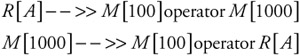
(2.9) 2-and-1/2-address instructions-This format uses two memory locations and a general register in the instruction. Typical of this type of instruction is an operation involving two memory locations storing the result in a register or an operation with a general register and a memory location storing the result on another memory location, as shown:
(2.10) 3-address instructions-Another less common form of instruction format is the three-address instruction. These instructions involve three memory locations-two used for operands and one as the results location. A typical format is shown:
(2.11)
2.3.2 Instruction architectures
There are numerous ideas about how to organize computer systems around the instruction set. One form, which has come of age with the new powerful workstations, is the reduced instruction set computer (RISC). These machines typically have a small number of instructions that are simple and that take a relatively short equal number of clock cycles per instruction. Each of the instructions is highly optimized and operates efficiently. Machine-coded programs are typically longer, but the actual code may run faster due to the highly optimized and regular code.
On the other side of the spectrum are architectures built around complex instructions. These computers are referred to as complex instruction set computers, or CISC. These machines use instructions that each perform some complex function-for example, a matrix multiply or a complex number manipulation trigonometric function. Each instruction may take numerous machine cycles to perform and may itself be coded in lower-level microcode. Programs written in this type of architecture may be shorter, but may not take any less time and in some cases may even take more time due to their complexity.
2.3.3 Memory-addressing schemes
Just as there are a variety of instruction formats, there are also numerous ways in which to determine the address of an operand from an instruction. Each form of address computation has its benefits in terms of instruction design flexibility. There are six major types of addressing computation schemes found in computers: immediate, direct, index, base, indirect, and two-operand. We will briefly examine these.
Immediate-Immediate addressing is not really an addressing mode into memory; rather, it is an instruction format that directly includes the data to be acted on as part of the instruction. This form of operand access simplifies the instruction execution cycle since no additional fetches are required.
Direct-For direct addressing there is no operand address decoding required. The instruction operand address field contains the physical address of the operand. The control simply places the operand address field into the memory address field and the operand is fetched from memory.
Index-A refinement of direct addressing is indexed addressing. In this form of operand address decoding, the operand address field is added to the contents of a designated register to compute the effective physical address.
Base-Base addressing expands on this concept. A base register contains an address base, which is added to the indexed address to form an effective physical address. This scheme is used in computer systems for addressing and partitioning the memory into segments. When more than one base register is available in an architecture, we can more easily manage partitioned memory for multiple users and systems control software.
Indirect-For this address computation scheme we use the contents of a specified memory location as the effective address. The control fetches the contents of the named memory location and uses this as the memory address register pointer to extract the actual operand.
Two-operand addressing-In two-operand addressing any combination of the above schemes could be used together to access multiple operands for an instruction.
2.3.4 Memory architectures
Memory storage can also have an architecture (configuration) that can aid in the storing and fetching of memory contents. Generally a memory is organized as a regular structure, which can be addressed using the memory address register and have data transferred through the memory data register (Figure 2.5). The memory is accessed through the combination of addressing and either drivers or sensors to write or read data from or to the memory data register. Memory structures are built based on the organization of the memory words. The simplest form is a linear two-dimensional structure. Each memory location has a unique word line, which, when energized, gates the N-bit lines' (where N is the size of a data word in the computer) contents into the memory data register.
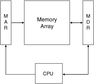
Figure 2.5: Memory access mechanism.
A second organization is the two-and-a-half-dimension architecture. In this memory structure the memory words are broken up into separate data planes, each consisting of one bit for all memory locations. To access a word the n planes must be energized with the composite X and Y coordinates, which correspond to the wanted memory word. The individual plane drivers gate the proper bit into the memory data register for the addressed memory word. Other data organizations have been derived and we leave it to the interested reader to investigate these.
|
| < Free Open Study > |
|
EAN: 2147483647
Pages: 136