In-Path Versus Out-of-Path Encryption with IPsec
| Design options that place the IPsec VPN tunnel termination endpoints directly in the data path refer to in-path IPsec VPN tunnel terminations. Figure 10-3 illustrates in-path versus out-of-path IPsec VPN design scenarios in which there is only one available interface for Demilitarized Zone (DMZ) access on the firewall. The administrator wants to encrypt certain traffic flows inbound through the firewall. However, for security reasons, all VPN traffic from and to the enterprise network must be encrypted and decrypted within the DMZ, hereby requiring an out-of-path design. If the firewall were able to terminate the IPsec VPN tunnels natively, without the use of an external IPsec VPN concentrator located in the DMZ, then an in-path design option (also illustrated in Figure 10-3) would be possible in this scenario. Figure 10-3. In-Path and Out-of-Path Design Options with Single DMZ IPsec VPN Tunnel Termination The considerable majority of design options in today's IPsec VPN environments are in-path. For this reason, among others, it is very common to see network nodes such as routers and switches embed integrated IPsec crypto engines and hardware-based crypto accelerators. The key design benefit of an in-path design is the ability to process crypto traffic in the fast switching path. This design benefit greatly boosts the overall performance of the IPsec VPN. Additionally, it enables network designers to incorporate hardware accelerators to increase performance in the crypto switching path even further. There are limitations with the next design option, out-of-path, that force crypto switching in the process switching path, thereby precluding hardware acceleration design options. In some scenarios, it may be necessary to place one or both IPsec VPN tunnel termination points outside of the data path. This is commonly referred to as "out-of-path" encryption. One such scenario that we've explored already is the use of IPsec tunnel termination on-a-stick. This scenario is also found when IPsec tunnels are terminated in firewalled environments, such as the one presented in Figure 10-4. In these scenarios, IPsec VPN termination points are typically located in a DMZ, which may require an out-of-path design. Figure 10-4. In-Path and Out-of-Path Design Options with Dual DMZ IPsec VPN Tunnel Termination Out-of-Path Encryption Design OverviewAlthough out-of-path encryption options include IPsec VPN tunnel termination "on-a-stick," this subset of IPsec VPN design alternatives is not limited to that one option. Out-of-path design options can include a single interface, or they can include multiple interfaces. Figures 10-3 and 10-4 illustrate DMZ designs in which inbound IPsec VPN tunnels are terminated on concentrators in the DMZ. Note the comparison of the equivalent in-path design option also illustrated in both options. Figure 10-3 places the IPsec VPN router on-a-stick. Although this option can be effective when required (e.g., due to limited available interfaces on the firewall, and so on), many on-a-stick scenarios require a loopback interface to operate correctly, forcing crypto traffic in to the process switched path. Figure 10-4 illustrates an out-of-path design alternative that does not place the IPsec VPN tunnel termination point on-a-stick. Instead, this dual-DMZ design provisions dual uplinks from the concentrator to the firewall, enabling the IPsec VPN concentrator or gateway to switch all crypto traffic in the fast switching path, and to leverage any available onboard crypto hardware assist resources for increased performance. Although there are ways of optimizing out-of-path design options for increased performance, in-path designs generally yield higher overall performance, as they eliminate the overall switching load of the system. Although the dual-DMZ design of Figure 10-4 yields some performance benefits over the single-DMZ design of Figure 10-3, both scenarios require the firewall to switch the packets at least twice (once in cleartext en route to the IPsec VPN gateway, and once in ciphertext inbound from the IPsec VPN gateway). The in-path design alternative would be to terminate the IPsec VPN tunnels on the firewall itself, or to use an integrated chassis-based solution with installed modules for firewalling and concentrating IPsec VPN tunnels. Note Examples of integrated solutions from Cisco Systems include the Catalyst 6500 line of switching platforms that support the Firewall Services Module (FWSM) and IPsec VPN Service Port Adapters (VPN SPA), and the Cisco Integrated Services Router that supports onboard IPsec hardware accelerators and IOS Stateful Firewalling. Although in-path design options generally provide increased performance, and are generally more common, there may be design scenarios in which the needs of the network infrastructure require an out-of-path solution. This is commonly found in DMZ designs, such as the one illustrated in the case study described in the following section. Case Study: Firewalled Site-to-Site IPsec VPN Tunnel TerminationA large marketing firm has increasingly relied on incoming data flows from partner organizations and feeds. As such, the organization is now revisiting its traditional strategy of accepting data feeds from those partners at the Internet-edge DMZ. The corporate IT department has proposed a pilot program to migrate connectivity between key partner organizations to a new extranet design currently in the planning process. The topology of the planned extranet project is illustrated in Figure 10-4. Although the firm's business is increasingly reliant on communications from key partners using the extranet described in Figure 10-4, the corporation's IT security staff is still concerned that the extranet presents an attack vector if one of the partner networks were to be breached. It is therefore determined that the extranet will deploy statefully redundant firewalls to protect the network against attacks across inbound VPN tunnel traffic from partners. The firewall uses a dual-DMZ approach to address two technical design challenges in firewalled site-to-site IPsec VPN deployments:
Example 10-5 provides the firewall diagnostics illustrating the settings for out-of-path IPsec VPN tunnel termination on the extranet deployment illustrated in Example 10-4. The firewall's security levels and interface IP addresses are configured in lines 1 through 16, allowing data to freely flow from inside networks to outside networks but not vice versa unless the firewall has the required state information to allow return traffic. The inside interface of the firewall is configured to passively listen for Routing Information Protocol (RIP) updates from other RIP routers on the local segment. The only exception to this passive behavior is that the firewall is configured to advertise a single default route to the other RIP routers on the segment. The firewall's routing table is displayed in lines 2026. Note there is a static default route pointing to the VPN concentrator on the inside DMZ interface. This effectively forwards all outbound L3 traffic to the concentrator cluster for encryption over the IPsec VPN tunnel. Of critical importance is the NAT and ACL entries on the firewall. Lines 2734 show an active NAT ACL that is used for translating inside IP addresses in to the inner DMZ interface facing the inside interface of the VPN concentrator. Only traffic matching the ACL will be NAT'd on egress to the PIX. Subsequently, any traffic exiting the firewall that does not match this ACL will not be translated and forwarded to the inside network. This effectively hides all inside IP addresses from the traffic exiting the concentrator. Instead, presenting only one interface with multiple translations for original traffic matching the NAT ACL on the PIX (NAT Overload or PAT), effectively allowing for added security. The named ACL "vpn-group" is the ACL referenced by NAT instance 1, making it a NAT ACL. Traffic matching this ACL on received on the inside interface will be translated in to the IP information referenced in by the corresponding global instance. The global instance below (1) maps to traffic matching the NAT ACL above. The traffic matching the NAT ACL will therefore be translated to the IP address of the inner-inner interface on the firewall. The static shown in line 36 allows the outside extranet partner's IPsec VPN gateways to reach the privately addressed VPN tunnel termination point (192.168.1.1) directly attached to the firewall's outer-outer interface using a public IP address (200.1.1.3) within the IP address range assigned to the outside interface (200.1.1.0/24). The named ACL, "vpn-control," allows crypto control plane traffic through the firewall to the outer-outer interface. ISAKMP traffic (UDP port 500) (IP protocol 50) must be allowed to the concentrator to establish the appropriate SAs, and ESP must be allowed to transport encrypted traffic between the IPsec VPN tunnel endpoints. Note that, although this effectively pokes holes through the firewall, they do not go all the way through to the inside interface. This ACL works with the static translation above to limit access from traffic matching this ACL only to the concentrator on the outer DMZ. There is no exception or ACL on the inner DMZ interface allowing crypto control plane traffic through. Example 10-5. Dual-DMZ Firewall Design for Extranet Edge IPsec VPN Tunnel Termination
In this dual-DMZ scheme, all IPsec VPN tunnel traffic is terminated in the outer DMZ. After the concentrator decrypts the traffic inbound across the IPsec VPN tunnel on the outer DMZ, it forwards the traffic back to the firewall on the inner DMZ interface in cleartext. Now that the packet is presented to the firewall in cleartext, the firewall is now capable of making another filtering decision based on the full contents of the packet. Figures 10-5 through 10-10 illustrate the required configuration of the VPN concentrators deployed in the design topology depicted in Figure 10-4. The VPN concentrators can be configured for network connectivity via a console port and command-line interface (CLI). Once the concentrator is configured for network access, the VPN3000 concentrator GUI can be used to configure and manage the concentrator over either HTTP or HTTPS sessions. Figure 10-5 displays the VPN3060 IP address configuration for the concentrator cluster illustrated in Figure 10-4. Figure 10-5. Dual-DMZ, Out-of-Path, VPN 3060 Concentrator IP Addressing VPN3000 concentrators support routing protocols, including Open Shortest Path First (OSPF), RIP, and static routing. Figure 10-6 illustrates the definition of a default static route on the VPN3060 concentrators depicted in Figure 10-4. Figure 10-6. Dual-DMZ, Out-of-Path, VPN 3060 Concentrator Routing Table Figure 10-7 illustrates the configuration of the VPN3060's active IKE policies to use for authenticating Phase 1 SAs inbound from remote branch offices. Figure 10-7. IKE Proposal Selection on the VPN 3060 Concentrator Although there are numerous preconfigured IKE proposals that can be activated on the VPN3060, they can be customized. Figure 10-8 provides an example of how to modify a preexisting IKE proposal on the VPN3060. Figure 10-8. IKE Proposal Configuration/Modification on the VPN 3060 Concentrator Figure 10-9 displays the required IPsec peering configuration for a site-to-site IPsec VPN tunnel negotiation with the remote branch, which is, in this case, a small home office hardware VPN client with the IP address 200.1.1.2. Here, the IKE proposal "IKE-3DES-SHA1-DH2" is used for Phase 1 negotiation, and 3DES ESP transform ("ESP-3DES") with 160-bit SHA1 MAC authentication ("ESP/SHA/HMAC-160") is used for Phase 2 SA negotiation with 200.1.1.2. Figure 10-9. Dual-DMZ, Out-of-Path, VPN 3060 IPsec VPN Tunnel Configuration (1 of 2)Peering, IKE, and Transforms Figure 10-10 provides a continuance of the screen capture provided in Figure 10-9, and also depicts the crypto-protected address space specification to use in the IPsec Phase 2 SA negotiated with 200.1.1.2. In this case, traffic originated from 192.168.2.2 to 30.1.1.0/24 is included in the crypto switching path. Figure 10-10. (Figure 10-9 continued)Dual-DMZ, Out-of-Path, VPN 3060 IPsec VPN Tunnel Configuration (2 of 2)Protected Address Space Definition In the design topology illustrated in Figure 10-4 and the corresponding configuration examples presented in Figures 10-5 through 10-10, data is taken slightly out-of-path to the outer DMZ then injected back in-path on the inner DMZ. Although this type of design requires more processing overhead on the firewall, it is very popular and is in many cases the optimal design choice when increased security surrounding the VPN tunnel termination point is required. Alternatives such as the one described previously are the methods of choice for many Internet edge, WAN edge, and extranet edge designs. Now that the firewalled dual-DMZ infrastructure has been deployed and the VPN concentrator is configured for site-to-site VPN tunnel termination from the extranet partners, the firm's IT staff takes several measures to verify the operation of the extranet infrastructure:
Figure 10-11. Verifying SA Establishment on the Extranet DMZ Concentrator Cluster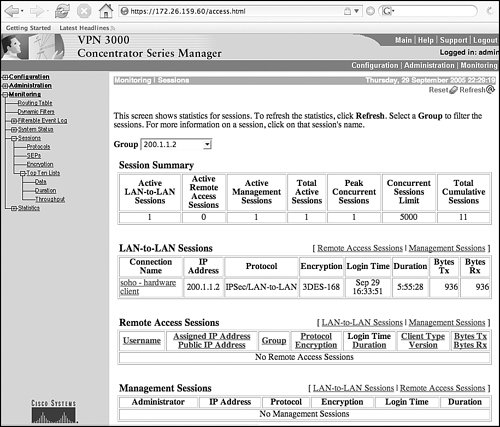 |
EAN: 2147483647
Pages: 113