| Most of today's enterprise class IPsec VPN deployments incorporate hub-and-spoke IPsec designs. These designs extend from the principles that we have discussed previously in this chapter, whether the situation describes the aggregation of native spoke IPsec VPNs at a hub IPsec aggregation point or the aggregation of IPsec+GRE VPNs at a hub IPsec and GRE concentrator. As the number of spoke connections increases, so do the number of design considerations surrounding the hub IPsec router. These include the following: SA Scalability The number of security associations actively supported and dangling SA detection, elimination, and management capabilities. This is less of a concern on spokes as they will only maintain SAs relevant to hub connectivity. Hub SA maintenance becomes an issue, as it must maintain an SADB comprehensive of all spoke VPN connectivity. IPsec Tunnel Capacity In addition to the number of SAs that the endpoint's memory can accommodate, one must pay careful attention to the security policy of the tunnel itself and the impact on the CPU that this policy has. Selection of the strongest cryptographic suites comes with a cost of increased computational burden. IPsec VPN design at a hub router that concentrates IPsec VPNs with strong security policies must be sized to accommodate the computational overhead required for tunnel maintenance of the appropriate anticipated scale. Crypto Path Switching Capacity The throughput, in packets per second (pps), of the traffic that is processed in the router's crypto (IPsec) switching path must also be considered. Or, if GRE is used, we must look at the throughput in (pps) of the GRE+IPsec switching path. GRE Tunnel Maintenance Capacity Although most routers will support GRE encapsulation, they do not necessarily do it in the fast switching path (in hardware). When selecting a hub router that will be concentrating GRE tunnels, care must be taken to ensure that extensive GRE encapsulation and decapsulation does not limit throughput or overburden the hub's CPU. Fragmentation Capabilities Because each spoke router in the network discovers the MTU en route to its destination, the amount of fragmented packets can potentially increase at IPsec aggregation points. Hub IPsec aggregation/concentration devices must be specified appropriately so as to handle potentially large amounts of fragmented packets sent from adjacent spoke IPsec peer endpoints.
Additionally, the urgency for HA at the hub router increases dramatically as additional spokes are reliant on the hub for connectivity to the enterprise's centrally located resources. Note This section on hub-and-spoke architecture only discusses HA items directly relevant to the physical layout of the IPsec VPNs themselves. IPsec HA design optimization in IOS, ASA, and VPN3K appliances is discussed comprehensively in Chapters 6 through 10.
Hub-and-Spoke Architectural Overview In this section, we will explore three common layouts for hub-and-spoke IPsec VPNs. The huband-spoke IPsec VPN model is one of the most commonly used and widely varied topologies in the IPsec VPN world today. Though the three models outlined in Figure 3-6 do not touch on all of these variations, we will use these three topologies as a framework for reviewing architectural considerations that are most commonly present in today's hub-and-spoke IPsec VPN designs. Figure 3-6. Hub-and-Spoke IPsec VPN Variations 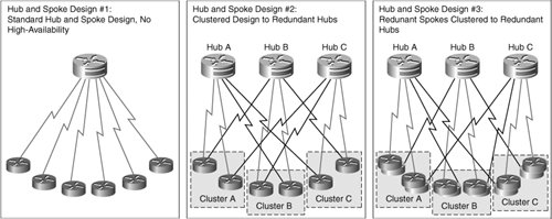
Standard Hub-and-Spoke Design without High Availability The simplest hub-and-spoke design consists of single-circuit, single-spoke connectivity to a hub router at a central facility, as described in the first design of Figure 3-6. This design, while simple from an architectural standpoint, does not allow much in the way of HA design enhancements, because this design is typically found in branch deployments that do not require high degrees of network uptime. From a performance perspective, the design considerations are focused largely on the hub. Because the spoke devices are maintaining minimal IPsec VPN tunnels and GRE tunnels, the IPsec and GRE performance is likely to be at the platform maximum when stressed. This is not the case for the hub router, which is responsible for SA and GRE maintenance to all of the spoke routers. This poses several design issues that must be addressed at the hub: SADB Scalability The hub router must have the appropriate amount of memory to accommodate the SADB for the whole hub/spoke deployment. Remember from our previous discussions in Chapter 2, "IPsec Fundamentals," that the number of IPsec SAs needed will be the twice the number of IPsec connections plus one SA for each IKE channel. Switching Capacity for IPsec Aggregation The hub router must have the appropriate amount of switching capacity (in pps) to support the performance requirements in the IPsec+GRE switching path. Excessive Encrypt/Decrypt Action for Spoke-Spoke Traffic For spoke-spoke connectivity, the hub router will be decrypting traffic from the sending spoke and re-encrypting it before sending it to the destination spoke. For networks that have a substantial amount of spoke-spoke traffic, the hub router that has enough processing power to support substantial amounts of decrypt/re-encrypt behavior must be selected. Tip Cisco IOS offers Dynamic Multipoint VPN (DMVPN) features that support the dynamic, direct establishment of spoke-to-spoke SAs in hub-and-spoke deployments. When deployed effectively, this solution can dramatically improve the performance of hub-and-spoke IPsec VPN deployments because IPsec processing is partially transitioned from the hub router to the spokes themselves. DMVPN is discussed in greater detail in Chapter 8, "Handling Vendor Interoperability with High Availability."
Multicast Fanout In this design, the hub router is performing the multicast fanout for traffic to all of the spoke routers that are subscribed to the multicast group. For traffic profiles that have substantial amounts of multicast traffic, the hub router must be capable of accommodating the appropriate amount of packet duplication, the encapsulation of those fanned-out packets in GRE, and the increased amount of IPsec processing that is required as those fanned-out packets are processed by the crypto engine.
Clustered Spoke Design to Redundant Hubs The second design in Figure 3-6 describes the addition of two hub IPsec aggregation points into the design. This allows network designers to deploy redundancy in the spoke uplinks to the hub routers. It also allows network designers to address the design concerns raised in the first design of Figure 3-6. Deploying redundancy at the hub location of the IPsec hub-and-spoke network presents some key design advantages, including, but not limited to, the following: Increased Tunnel Termination/Maintenance Capacity Using multiple hub routers decreases the amount of memory required for SA maintenance on a per-platform basis, because the SAs are spread across three aggregation points (as opposed being concentrated on only one). The distribution of hub processing capabilities also eases the computational burden in terms of IPsec VPN termination, GRE tunnel termination, and the decryption/re-encryption overhead of spoke-to-spoke communication discussed previously. Increased Multicast Fanout Capacity Distributed Hub IPsec processing also presents two additional multicast fanout points to the design. This type of distribution at the multicast fanout points can dramatically improve the switching performance of the hub-and-spoke deployment, because computational resources for copying multicast packets, encapsulating them in GRE, and encrypting them are tripled at the aggregation points. Load Balancing and Redundancy In addition to the redundancy provided to the spokes by the two redundant uplinks to their corresponding aggregation points, the correct deployment of redundant circuits allows for a primitive form of load balancing across the three aggregation pointsHubs A, B, and C. Each spoke terminates its primary uplinks on different hubs so that in a nonfailover scenario IPsec VPNs are distributed evenly across the three aggregation points. Each spoke's backup links are distributed in the same fashion, so as to provide the same load-balancing effect when there is a failover scenario at the spoke.
Redundant Clustered Spoke Design to Redundant Hubs Design #3 in Figure 3-6 describes a topology similar to Design #2, but with redundant routers at the spoke. This is the most highlyavailable design discussed in this chapter, and it will lead us in to design concepts discussed in Chapters 610. It is also the most expensive of the three designs to deploy, as it doubles the amount of hardware to be purchased at the spoke level. With respect to the design of the IPsec VPNs themselves, the addition of redundant spoke routers could boost performance of the IPsec VPN, especially if both IPsec tunnels were concurrently active and traffic from the spoke is load-balanced across the two redundant spoke routers. These benefits, however, although useful, are only local to the spoke itself, which is why it is more common to invest in redundancy and load-balancing improvements at the hub before adding it to the spokes. Additionally, large-scale deployment of redundant spoke routers will require more processing capability to accommodate increased IKE processing, or increased SADB capacity if a "hot" standby model is required (see Chapters 610 for design concepts surrounding IPsec HA in IOS). Because of this, the primary benefit of adding an additional, redundant, router to a spoke in the greater hub/spoke design is redundancy at that particular branch. For this reason, it is most common to see only highly-available branches pursue this design, while other spokes are deployed using the framework we have discussed in Designs #1 or #2. The cost-benefit analysis of pursuing redundant uplinks and redundant routers at the spoke must be weighed carefully against the cost (both computational and monetary) of deployment. It is rare to see blanket rollouts of Designs #1, #2, or #3 shown in Figure 3-6. Instead, it is much more common to see designs that incorporate elements of all three designs on a per-spoke performance and HA-requirementbasis. |