Site-to-Site IPsec VPN Deployments
| The most basic form of IPsec VPN is represented with two VPN endpoints communicating over a directly connected shared media, or dedicated circuit, which closely resembles bulk encryption alternatives at Layer 1 and 2 of the OSI stack (see Table 1-1 for VPN technologies and the OSI stack). This scenario, while simple to deploy and manage, can be cost prohibitive and does not yield many of the benefits of IPsec VPN connectivity over a routed domain (multiple Layer 3 hops between endpoints). Indeed, because IPsec is a Layer 3 VPN technology, it was designed to function across multiple Layer 3 hops in order to circumvent many of the scalability and manageability issues in previous VPN alternatives. As such, IPsec deployed over a routed domain will also provide further scalability, flexibility, and availability over and beyond the simple dedicated-circuit model. In this section, we will explore design concepts related to both topologies and the corresponding configuration and verification processes required. Site-to-Site VPN Architectural Overview for a Dedicated CircuitSite-to-site IPsec VPNs are typically deployed when two or more autonomous systems wish to communicate with each other over an untrusted media when confidential exchange of data is required. Consider the situation described in Figure 3-2, where three autonomous systems wish to communicate using dedicated T-1 circuits between each pair. Figure 3-2. Site-to-Site IPsec VPN Topology Using Dedicated T-1 Circuits for Communications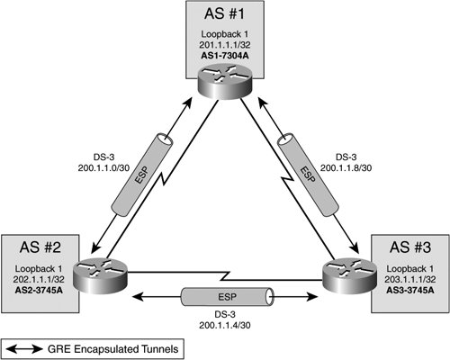 It is important to note that, assuming that each autonomous system (AS) does not act as a transit AS, there is only one path between each AS. Therefore, in this specific case, there is no benefit to configuring redundant peering options or sourcing IPsec tunnel endpoints from highly available IP addresses (such as a loopback address). In this simple site-to-site topology, it is most common to source IPsec VPN tunnel endpoints on the physical interfaces (DS-3 in this case) themselves. This type of topology does not leave room for much in the way of IPsec HA design, and therefore, it is relatively simple to deploy. We will now explore the configuration steps necessary to establish the basic site-to-site IPsec VPN described earlier, and then we will outline some common techniques used to verify the establishment and operation of the IPsec VPN tunnel. Cisco IOS Site-to-Site IPsec VPN ConfigurationThe configurations in the following examples were all built using the process described in Figure 3-1 and pertain to the topology depicted in Figure 3-2. Some design considerations for these particular IPsec VPNs are as follows:
Note The preceding VPN considerations describe a relatively strong cryptographic suite. As such, computation resources on the routers must be somewhat substantial to accommodate them. It is important that one weigh the amount of available computational resources against the organization's performance and security requirements before building IPsec VPN configurations. Example 3-1 provides a configuration for the AS1-7301A in Figure 3-2. This router's configuration employs all of the elements necessary to accommodate a site-to-site IPsec VPN, including the IPsec transform, crypto ACL, and IPsec peer. In this case, AS1-7301A uses two site-to-site IPsec VPNs, to AS#2 and AS#3, respectively. This is accomplished by using two process IDs within the same crypto map (AS1VPN 10 and AS1VPN 20). AS1VPN, process 10, protects traffic from AS1 to AS2, as defined in Crypto ACL 101. AS1VPN, process 20, protects traffic from AS1 to AS3 (Example 3-1, line 14), as defined in Crypto ACL 102 (Example 3-1, line 15). Example 3-1. Site-to-Site VPN Configuration on AS1-7301A
Example 3-2 provides the configuration for the IPsec VPN gateway for AS2, AS2-3745A. Like AS1-7304A, AS2-3745A uses a single crypto map with two process IDs to protect traffic flows to AS1 and AS3. AS2VPN 10 protects traffic to AS1 (endpoint 200.1.1.1), and references ACL101 for crypto-protected traffic and IPsec transform "ivdf3-1." AS2VPN 20 protects traffic to AS3 (endpoint 200.1.1.6), and references ACL102 for crypto-protected traffic and IPsec transform "ivdf3-1." AS2-3745 uses a relatively strong transform, AES cipher with SHA1 HMAC authentication. PFS is also configured to refresh the symmetric transform key each time an IPsec SA is negotiated. Example 3-2. Site-to-Site VPN Configuration on AS2-3745A
Example 3-3 provides the configuration for the IPsec VPN gateway for AS3, AS3-3745A. Like AS1-7304A and AS2-3745A, AS3-3745A uses a single crypto map with two process IDs to protect traffic flows to AS1 and AS3. AS3VPN 10 protects traffic to AS1 (endpoint 200.1.1.9), and references ACL101 for crypto-protected traffic and IPsec transform "ivdf3-1." AS3VPN 20 protects traffic to AS3 (endpoint 200.1.1.5), and references ACL102 for crypto-protected traffic and IPsec transform "ivdf3-1." AS2-3745 uses a relatively strong transform, AES cipher with SHA1 HMAC authentication. PFS is also configured to refresh the symmetric transform key each time an IPsec SA is negotiated. Example 3-3. Site-to-Site VPN Configuration on AS3-3745A
Verifying Cisco IOS Site-to-Site IPsec VPN OperationNow that we have configured a full mesh of IPsec VPN tunnels between AS#1, AS#2, and AS#3, we must take some basic precautionary measures to guarantee that the VPN is operating successfully:
Examples 3-4 through 3-7 provide examples of these verification tasks on AS1-7304A in Figure 3-2. First, we verify that an ISAKMP SA has been successfully established. Example 3-4 confirms that there are indeed two ISAKMP SAs established to AS2-3745A and AS3-3745A. Note that these SAs are in "QM_IDLE" state, meaning that the ISAKMP SA is authenticated and can be used for subsequent Quick Mode (Phase 2) exchanges. The ISAKMP SA can exist in a number of other states. These states are described in Table 3-1 for ISAKMP SA negotiation in Main Mode.
Though the SA described in Example 3-4 was negotiated using Main Mode, Aggressive Mode could have been used instead. Table 3-2 presents the ISAKMP SA states and their descriptions for SAs negotiated with Aggressive Mode. Note that in Table 3-2, there are inherently fewer states described for Aggressive Mode, because Aggressive Mode involves fewer message exchanges than does Main Mode.
Example 3-4. Verification of ISAKMP SAs for AS1-7304A
After we can verify that Phase 1 SAs are established (by examining the output listed in Example 3-4), we are then ready to verify the establishment of IPsec SAs. Example 3-5 provides output needed to verify several important elements of Phase 2 SA establishment:
Note These statistics will change to match the crypto engine statistics listed in Example 3-7 after traffic is sent across the tunnel in Example 3-6. Example 3-5. Verification of IPsec SAs for AS1-7304A
In Example 3-6, we will attempt to send traffic across both IPsec VPN tunnels to the remote peers on AS2-3745A and AS3-3745A, respectively. First, we display the crypto-protected address spaces by displaying the ACLs referenced in the crypto map. Next, we send 100 ICMP echo requests to both peers. Note that in both cases, we drop the first ICMP packet during IKE and IPsec SA negotiation. Example 3-6. Verification of Connectivity along the Crypto Path
After we have successfully sent traffic to the remote crypto endpoints, we must then verify that it was successfully encrypted by the IPsec crypto engine. Example 3-7 provides the active IKE and IPsec SAs resident in the crypto engine for AS1-7304A. Note that the SAs with IDs 1 and 2 have not increased their packet count. This is expected, because these are the ISAKMP SAs (the same ones previously displayed in Example 3-4). Because IPsec SAs are unidirectional, we confirm that there are 4 SAs present in AS1-7304A's SADB:
We can confirm that the SA from AS1-7304A is actively encrypting echo requests to AS2-374A (99/100 corresponds to the success rate of Example 3-6) and that the SA received from AS2-3745A is actively decrypting the echo replies sent from AS2-3745A to AS1-7304A (also 99/100, corresponding to the success rate of Example 3-6). The same behavior is confirmed for the two SAs built between AS1-7304A and AS3-3745A (Example 3-7, SA ID #2002 and #2003). Example 3-7. Crypto Engine Verification
Site-to-Site Architectural Overview over a Routed DomainThe design considerations of a site-to-site IPsec VPN change considerably once the underlying transit media changes. Consider the preceding site-to-site IPsec VPN examplehow would our design change if we were to replace the existing dedicated DS-3 links between ASs with DS-3 uplinks to an Internet service provider? Network designers face the challenge of dealing with multicast traffic in the crypto switching path. Multicast traffic, including Interior Gateway Protocol (IGP) multicast hellos and multicast data feeds, cannot be sent natively across an IPsec VPN tunnel. Instead, the multicast data must be encapsulated with unicast header (such as IP generic routing encapsulation (GRE)) before being presented to the IPsec crypto engine. Typically, these design considerations have encouraged the use of leased-line connectivity for VPN extension and the insertion of GRE tunnels through the IPsec tunnel (commonly referred to as IPsec+GRE) to accommodate the multicast traffic associated with the routing protocol updates and hellos. The need for enterprise connectivity extension across intermediate routed domains is growing rapidly. Two common enterprise IPsec deployments that are driving this growth are corporate extranet deployments and RAVPN deployments. Consider the following example, in which a large automotive manufacturer wants to securely extend connectivity from its corporate headquarters network to a series of smaller home offices over an independently maintained routed domain, such as the Internet. The smaller branch offices consist of a number of routed nodes and, as such, would benefit from getting Route Processor (RP) updates from the campus network. Figure 3-3 demonstrates how the addition of a site-to-site IPsec VPN across the independently maintained routed domain would preclude the smaller home offices from exchanging RP updates with the campus network at the corporate HQ. Figure 3-3. IPsec RAVPN Extension to Small Home Office over the Internet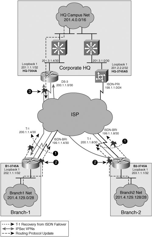 Due to IPsec's inability to natively encrypt multicast traffic, the design in Figure 3-3 presents the following design considerations:
The solution to these design considerations is to add GRE tunnels to the IPsec VPN implementation. RP traffic between the corporate HQ and branch networks will then be encapsulated with GRE headers and forwarded in the crypto switching path across the ISP network. We will discuss IPsec+GRE architectures in greater detail later in this chapter. Consider the following example, in which a corporation, a large global financial organization, wants to allow extranet connectivity to its partners. The primary use of this extranet connection is to stream multicast data containing video and market information to decision makers within the global financial organization. This must be done securely and with confidentiality. The insertion of an independently maintained routed domain between the corporate extranet partner and the global financial organization breaks the multicast tree between the two parties, as illustrated in Figure 3-4. Figure 3-4. Corporate Extranet Connection Using Internet Uplinks and IPsec VPNs The extranet model breaks multicast in two areas. First, underlying media is not configured to support peripheral interface manager (PIM) or multicast routing. Therefore, even without IPsec, the multicast tree would never form properly with this deployment. Second, assuming that the multicast tree could be established, IPsec would fail to send multicast flow in ciphered format. Again, the addition of GRE to the corporate extranet would allow extension of PIM traffic across the Internet. Additionally, because the PIM updates are encapsulated in GRE prior to encryption, the PIM packets encapsulated in GRE would be processed in the crypto switching path and forwarded securely across the IPsec VPN. Tip The Cisco V3PN solution outlines a VPN architecture that accommodates voice and video over IPsec. Because IP multicast is a key component of many voice and video streaming technologies, V3PN requires the use of IPsec+GRE. For more information on V3PN, please refer to the following documentation on CCO http://www.cisco.com/en/US/partner/netsol/ns340/ns394/ns171/ns241/networking_solutions_sub_solution_home.html |
EAN: 2147483647
Pages: 113
- ERP Systems Impact on Organizations
- The Second Wave ERP Market: An Australian Viewpoint
- Enterprise Application Integration: New Solutions for a Solved Problem or a Challenging Research Field?
- The Effects of an Enterprise Resource Planning System (ERP) Implementation on Job Characteristics – A Study using the Hackman and Oldham Job Characteristics Model
- Development of Interactive Web Sites to Enhance Police/Community Relations