The IP Security Protocol (IPsec)
| IPsec provides us with a framework by which to secure data communications at the network layer of the OSI model, or, more specifically, to secure IP communications. In order to do so, the IPsec standard incorporates a number of protocols into the IPsec protocol suite. As such, IPsec is not defined as a single protocol, but is instead a collection of protocols, each focusing on particular elements of the IPsec missionto secure IP communications over untrusted networks. We've discussed in detail the operation of many different cryptographic components designed to deliver services such as data authentication, data confidentiality, data integrity, and data nonrepudiation to IP communications. Within the IPsec protocol, there are protocols that provide a means by which to ensure all of these services in a VPN implementation. This assurance is the reason that IPsec is widely considered to be one of the most comprehensively effective VPN choices available in enterprise and commercial markets today. Examples of protocols included in the IPsec protocol suite that are focused on delivering message authenticity, data integrity, data confidentiality, and sender nonrepudiation include IKE for authenticity and the Encapsulating Security Payload for confidentiality. We will explore these protocols and others as we present a comprehensive overview of the mechanics of IPsec. IPsec VPNs encrypt data at the Layer-3 IP packet layer, offering a comprehensively secure VPN solution through providing data authentication, antireplay protection, data confidentiality, and data integrity protection. As such, IPsec is one of the most widespread VPN technologies in today's enterprise, service provider, and government networks. IPsec in tunnel mode supports the rewriting of type-of-service (ToS) bits into an IP header placed directly outside of the IPsec header, and, as such, supports encrypted data payloads while preserving the operation of quality of service (QoS) in a IP network. IPsec is a standards-based protocol, and can therefore operate seamlessly across a network built with technologies from multiple vendors. As we'll see moving forward, IPsec is supported within Cisco IOS on a wide array of different routers, switches, VPN concentrators, and VPN clients. Likewise, Cisco offers a variety of different hardware-based VPN acceleration options for optimal VPN performance within a network. IPsec will serve as the primary VPN discussion point for the duration of this book. Moving forward, this chapter uses the approach in Figure 2-11 to lay out the fundamentals of IPsec communications. Figure 2-11. An Overview of IPsec Mechanics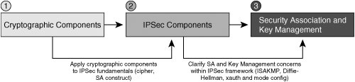 IPsec ModesIPsec uses two different modes to establish a secure communication channel between network nodesTransport Mode and Tunnel Mode. The secure communications channel that IPsec provides is commonly referred to as an IPsec SA. IPsec and IKE SAs are discussed in greater detail later in this chapter. Note IPsec security associations are unidirectional. As such, when two cryptographic endpoints use IPsec to create a secure communications channel between each other, there are two IPsec SAs involvedone in each direction. IPsec modes have different applications in different architectures. This is due largely to the fact that tunnel and transport modes protect different parts of the IP packet, yielding different degrees of confidentiality. The key choice in selection of an IPsec operational mode is determination of what parts of IP headers and payloads are to be kept confidential. Transport ModeRFC 2401 defines a transport mode SA as one that connects two IPsec hosts together. In IPsec transport mode SAs using Encapsulating Security Payload (ESP), only upper-layer protocols are kept confidential. This is because the ESP-encapsulated payload starts after the IP header and options. Figure 2-12 illustrates the resulting format of an ESP-encapsulated IP packet using transport mode. Figure 2-12. An ESP-Encapsulated IP Packet Using Transport Mode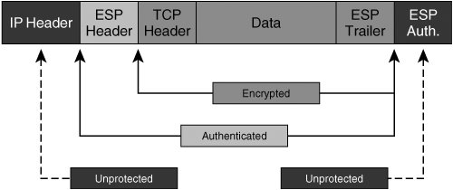 Tunnel mode places the ESP header before the IP header, offering confidentiality for IP-encapsulated payload, IP header, and options. So why would one ever choose transport mode? In some instances, features within the IP header might be better off left in the clear. Take the example of a network in which a conversation-based QoS technique, such as Weighted Fair Queuing, is critically required. In an IPsec SA using tunnel mode, this information would typically be located inside the ESP-protected boundary. As such, network devices attempting to make queuing decisions will not be able to appropriately hash the data into the correct conversation. Figure 2-13 illustrates this potential interoperability consideration. Figure 2-13. Flow-Based QoS Inconsistency in Tunnel Mode IPsec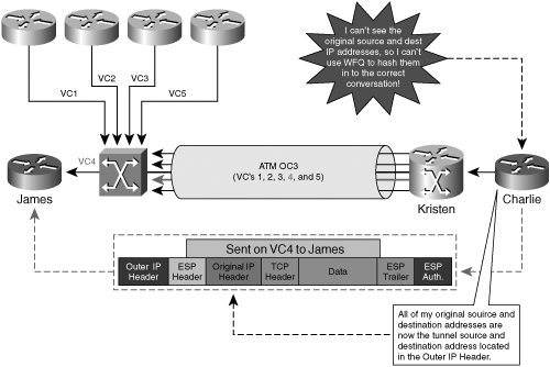 Tip Using the QoS preclassify feature in IOS 12.1T or later IOS can preserve the operation of Weighted Fair Queuing on the IPsec endpoint. If the SA created in Figure 12-13 between James and Charlie were transport mode, the original source and destination addresses would be visible. If inner IP header information is not deemed to be confidential information by security administrators, then transport mode can be employed to maintain per-conversation QoS consistency. Note that the scenario above describes one such inconsistency between IPsec and QoS techniques in IP networks, but there are others. We will discuss challenges of designing QoS into an IPsec VPN in greater detail in Chapter 4, "Common IPsec VPN Issues." Tunnel ModeTunnel mode IPsec SAs have different protection boundaries from transport mode SAs. In a tunnel mode SA, not only are upper-layer protocols afforded confidentiality services, but the IP header information is also protected. IP communications are maintained within the IPsec tunnel by creating an "outer" IP header that is prepended to the outside of the ESP-protected boundary. Figure 2-14 illustrates the format of an ESP-encapsulated IP packet in tunnel mode. Figure 2-14. An ESP-Encapsulated IP Packet Using Tunnel Mode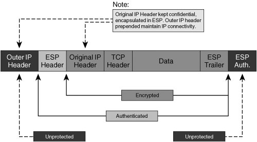 Tunnel mode defines a broader protective boundary at the packet layer, and hence provides a greater scope of confidentiality. In doing so, tunnel mode hides useful attributes of the IP header from intermediary network devices between the two tunnel endpoints. Measures can be taken to carry forward useful information from the original IP header into the outer IP header. However, when doing so, there is a corresponding decrease in the overall level of confidentiality of the packet itself. Per RFC 2401, secure IPsec gateways commonly use tunnel mode when establishing an IPsec SA with another IPsec host or IPsec secure gateway. We will explore many design concepts pertaining to the appropriateness of IPsec tunnel mode and transport mode in subsequent chapters. IPsec TransformsAs discussed above, IPsec delivers data confidentiality services by executing a transform on plain text data. Common ciphers used in the IPsec transforms are DES, 3DES, and AES. All of these transforms conform to specifications for IPsec's symmetric-key cryptographic requirements per RFC 2401. Another item that all of these transforms have in common is that they can all be deployed in using ESP, authentication headers (AH), or a combination of the two. ESPESP provides a combination of security services for IPsec-processed IP packets. Examples of the services offered by ESP include data confidentiality, data origin authentication, data integrity assurance mechanisms, and data flow confidentiality. The services offered by ESP depend on which services are negotiated during IPsec security association establishment. As such, any service, or combination of services, can be selected by the administrator before SA negotiation takes place. ESP can be deployed in transport or tunnel mode. Additionally, it can be deployed alone, or in conjunction with authentication headers. EncryptionMessage and Traffic-Flow ConfidentialityESP provides confidentiality services by allowing the use of popular symmetric key encryption ciphers such as DES, 3DES, and AES. Assuming that a user selects DES as their transform cipher, the encrypting device would take input data at 64-bit blocks and encrypt them using a key 56 bits in length. ESP would then "wrap," or encapsulate, the ciphered payload with an ESP header (IP protocol number 50). The 64-bit blocks of the original message can be chained together using cipher block chaining (CBC) or CFB, yielding greater antireplay and data integrity protection. The format of an ESP-processed IP packet varies based on which IPsec transform mode is selected. In transport mode, the header is placed before the ciphered payload, and after the IP header. As such, ESP in transport mode offers only confidentiality protection for Layer 47 protocol informationit is effective at providing confidentiality to the IP-encapsulated payload of the original message. To increase the protective boundary of ESP on a per-packet basis, administrators can select tunnel mode when defining their IPsec transforms. ESP in tunnel mode includes the original IP header in the ciphered payload. The ESP header is placed before the ciphered inner IP header, and after the cleartext outer IP header. As such, IPsec in tunnel mode protects the source and destination of the IP traffic flows themselves, in addition to Layer 47 protocol information protected in transport mode. Note 3DES and AES are considered to be stronger encryption ciphers than DES, as they use longer encryption keys (128-bit key for 3DES and 256-bit key for AES). However, they are also more computationally expensive, and administrators should therefore carefully balance the need for confidentiality with the cost of their VPN infrastructure. Each ESP packet is marked with a security parameter index (SPI). The SPI enables encrypting and decrypting devices to understand which SA the ESP packet belongs to. SPIs are a 32-bit arbitrarily derived by the destination IPsec peer during IKE. Using SPIs to identify the packet's appropriate SA is critical, as each SA may be processed under a variety of different parameters, such as selected encryption transforms and Diffie-Hellman keys. In addition to the SPI, a sequence number is created for each ESP packet. Sequence numbers increase incrementally, per packet, offering built-in antireplay protection for ESP-processed traffic in both tunnel (Figure 2-14) and transport mode (Figure 2-12). Data Authentication and IntegrityESP defines a built-in authentication header, in the form of a Keyed-HMAC. This HMAC is inserted in to the ESP header to provide data integrity and authentication services to the ESP-processed traffic. In the context of IPsec, an HMAC would be specified as part of the transform selected. IPsec provides us with all of the ingredients necessary for building an HMAC, such as a shared secret key (typically derived through Diffie-Hellman exchange), a hash function (IPsec RFC accepts MD 5 and SHA-1), and fixed message input. Note Message input for creating an HMAC, in this case, is the ciphered format of the original message, as ESP authentication always occurs after encryption. Warning MD 5 HMACs, though supported, are relatively vulnerable and prone to a higher likelihood of collisions. Cisco recommends the use of SHA-1 HMACs instead of MD 5 HMAC authentication whenever possible. The following sequence of operations is executed when dissecting a cleartext message into data blocks for symmetric encryption during ESP encapsulation and then creating and appending HMACs to each block for increased message authenticity.
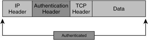
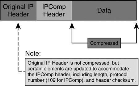
Note Cisco VPN devices enable network administrators to specify authentication header options within ESP transforms using MD 5, SHA, or null (no authentication) hash functions. As we've discussed before, symmetric key algorithms used in ESP can leverage mechanisms such as CBC to securely chain ESP-processed packets together. CBC leverages ensure that repetitive plain text input does not yield identical cipher text within the same sequential block. This is accomplished by including a feedback step that chains blocks together in a sequence. The feedback for the first block in the sequence is referred to as the Initialization Vector (IV), and is derived randomly. Symmetric key transforms using CBC protect data from the malicious insertion of data between chained blocks and from the malicious derivation of plain text input into a non-CBC chained cipher text stream. AHWhen confidentiality is not required, administrators can choose to deploy IPsec with AH, instead of with ESP. IPsec AH was created with the intention of providing data authenticity and integrity services to as much of the IP packet as possible. IPsec AH yields data authenticity, antireplay, and data integrity services by appending an additional field, called the authentication header, protecting the data payload and parts of the original IP header. Unlike ESP, however, IPsec AH does not provide data confidentiality. Because AH authenticates parts of the IP header, AH protects both upper- and lower-layer information within the IP header, while ESP protects only upper-layer protocols in transport mode. Figure 2-15 illustrates the format of an IP packet encapsulated with Authentication Headers using transport mode. Figure 2-15. IPsec Authentication Headers in Transport Mode Like ESP, AH can be deployed in transport mode and in tunnel mode. In tunnel mode, AH copies parts of the inner IP header that are used to create a new, outer IP header. AH in tunnel mode provides data authenticity and integrity to all of the original IP header and payload elements, and also to parts of the new outer IP header. Figure 2-16 illustrates the format of an IP packet encapsulated with Authentication Headers in tunnel mode. Figure 2-16. IPsec Authentication Headers in Tunnel Mode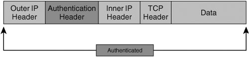 Like ESP encapsulation, AH encapsulation also employs SPIs so that the appropriate SA can be located for a given IP packet. IP Payload Compression Protocol (IPPCP) and LZSWhen deploying confidentiality services using IPsec, encrypting the IP payloads renders many lower-layer protocol compression mechanisms, such as PPP Compression Control Protocol, ineffective. IPComp provides a framework for compressing IP packets in VPN environments that use encryption for confidentiality purposes. IPPCP compresses the IP datagram in full, including IP header. In this process, an IPPCP header is inserted immediately before this new IPPCP-compressed payload. Figure 2-17 illustrates the resulting format of an IPPCP-compressed IP packet. Figure 2-17. Compression Results of an IP Packet Using IPPCP IPComp is a nonlossy compression protocol, meaning that the decompression of each individual packet represents the original unencrypted packet. As such, IPComp is also considered to be statelessthe decompression and compression of a given packet does not depend on any other packet being processed. Lempel Ziv Stac (LZS) is a very efficient compression algorithm that is being used in conjunction with IPComp in many VPN operations. LZS is capable of compression strings as short as two octets in length. In order to effectively support compression in IPsec environments that use encryption for confidentiality, compression of the data payload must occur before the packet is compressed. IPComp requires the negotiation of an IPComp Association (IPCA) between a pair of compressing and decompressing nodes. Components that the two nodes must negotiate when building an IPCA are:
One key element of IPComp and LZS is that IPCAs can be negotiated using ISAKMP. As such, not only do IPComp and LZS provide an efficient mechanism for compressing encrypted IP packets, but it also cleanly and securely integrates into IPsec negotiation using ISAKMP and IKE. IPsec SAWhen two nodes decide to establish IPsec connectivity to one another, they must agree on certain parameters in order for the IPsec tunnel to be established and function properly. IPsec and ISAKMP both employ a SA to accomplish this. IPsec SAs negotiate a number of security parameters necessary to secure the IPsec tunnel, and for the two IPsec peers to maintain the IPsec tunnel effectively:
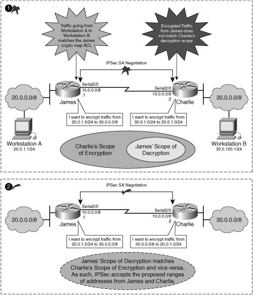
Figure 2-19 illustrates the use of SPIs in a standard IPsec VPN hub-and-spoke topology. Figure 2-19. SPI Usage in Hub-and-Spoke IPsec VPN Deployment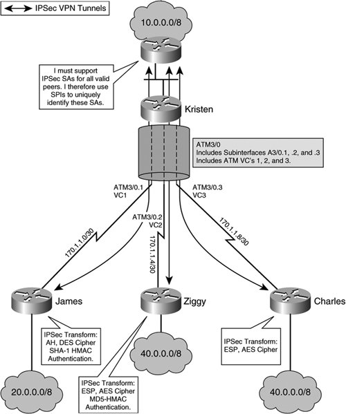 IPsec SAs are unidirectionalin one direction only. As such, an IPsec tunnel must establish at least two SAsone from source to destination and one from destination to source. Note IPsec requires the negotiation of a unique SA for each direction of the IPsec tunnel and for each protocol used (AH, ESP, or combination thereof). Within the IPsec protocol suite, there is another, different, type of SA that must be negotiated before an IPsec SA can be negotiatedthe IKE SA. When dynamic keying is used, IKE SAs are negotiated in order to establish a secure channel over which to negotiate security parameters needed to form an IPsec SA. Figure 2-20 outlines the necessary steps that two nodes must follow when building IKE and IPsec SAs. Figure 2-20 illustrates the basic process of negotiating IKE (Phase 1) and IPsec (Phase 2) SAs. Figure 2-20. IKE and IPsec SA Negotiation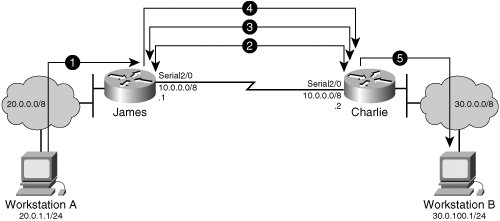 The following sequence of events describes the negotiation if IKE and IPsec SAs relate to the illustration provided in Figure 2-20:
For subsequent packets, the process starts at Step 4, because the SAs have been established. After a defined interval (or data volume), the SAs will time out, and the next packet after this will trigger the SA establishment process again. IPsec Configuration ElementsThere are several basic tasks that must typically be addressed when implementing IPsec. In this section, we will explore basic tasks common to most of the fundamental IPsec VPN implementations, including the creation of an IPsec transform set and the successful configuration of an IPsec crypto map. Creating an IPsec TransformIn order to implement an IPsec VPN, the administrator must first make a series of decisions that will eventually result in the creation of the IPsec transform. The IPsec transform defines a series of parameters that will be used in transforming the packet from its cleartext input form to the cipher text output. Figure 2-21 illustrates the IPsec transform creation decision tree. Figure 2-21. IPsec Transform Creation Decision Tree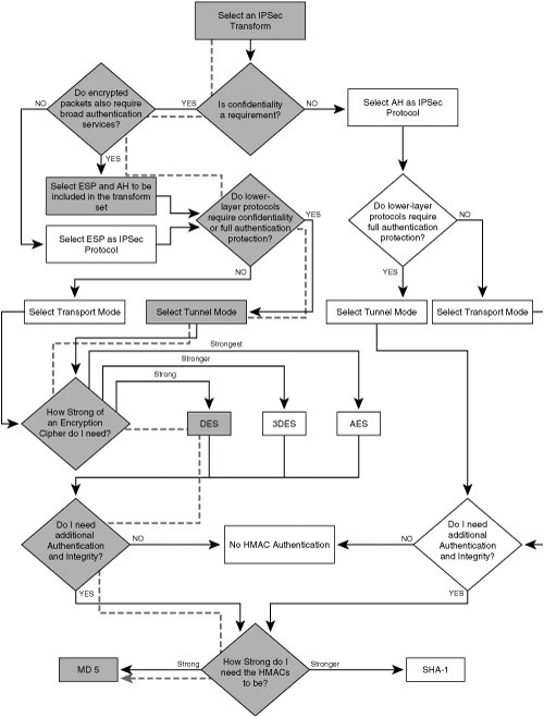 The following list and examples use Figure 2-21 to illustrate the creation of a transform set within IOS:
As one may have inferred, not all of the above parameters must be selected. For example, one can choose not to include authentication headers in a transformed payload and only select ESP. Likewise, no authentication method can be selected when defining transforms. As such, it helps to think of transform creation as a series of sequential decisions as depicted by the flowchart in Figure 2-21. Note In Figure 2-21, the path that James had chosen to select his transform in Examples 2-1 and 2-2 is noted with shading. As we'll see in later sections of this book, Charlie must be configured with a transform set that matches James' for the IPsec tunnel to negotiate properly. The transform set defines a variety of security parameters that will be negotiated over IKE when IPsec SAs are formed. Crypto Map ConfigurationTransform processes are performed at the interface level, and are therefore not activated until they are bound to an interface, or group of interfaces, using a crypto map. In IOS, crypto maps are used for a variety of different configuration items that are discussed in later sections of this chapter, including PFS, TED, x-Auth, and other options. At a minimum, a crypto map must be configured with three items before it is activated by IOS:
Consider Charlie's configuration of a crypto map when setting up an IPsec tunnel to James in Figure 2-20. It is assumed that Charlie has configured a transform set named "IPSECVPN-1" that matches the one that James had configured in Examples 2-1 and 2-2. Charlie matches any SMTP traffic destined James 20.0.0.0/8 network by referencing ACL 101 in his crypto map. Last, Charlie defines James' serial interface IP address as the IPsec tunnel endpoint so that IPsec understands which destination the Charlie's IPsec SA to James (rememberIPsec builds two unidirectional SAs) should reference. Example 2-3 illustrates Charlie's configuration of the three minimal objectives to establish his crypto map and the binding of the crypto map to his serial interface. Charlie configures a crypto map to communicate with James via IPsec. To achieve this, Charlie configures a crypto map named "IPSECMAP-1," as illustrated in line 5 of Example 2-3. He then selects ISAKMP over manual keying, allowing Charlie and James to dynamically establish a secure channel over which to negotiate IPsec SAs. When Charlie builds his crypto map, IOS warns that an ACL, peer, and transform must be configured for the crypto map to be activated. Charlie references access-list 101 as traffic to be processed by IPsec in this crypto map (Example 2-3, line 8). Charlie selects the IP address of James' serial interface as the IPsec tunnel endpoint to be referenced in the IPsec SA (Example 2-3, line 9). Transform set "IPSECVPN-1" is then selected as the transform to be executed on traffic matching ACL 101, as illustrated in Example 2-3, lines 8 and 11, respectively. When Charlie wants to encrypt e-mail traffic (SMTP) destined to James (hosts on 20.0.0.0/8), he sets up ACL 101 to reference SMTP traffic destined to that subnet and tells IPsec to use ACL 101 when deciding which traffic to process in IPsec (see above crypto map entry). Finally, Charlie binds the crypto map to his egress interface toward James, the intended IPsec tunnel endpoint (Example 3-1, line 15). To communicate with Charlie using IPsec, James first configures a crypto map named "IPSECMAP-1." He selects ISAKMP over manual keying, allowing Charlie and James to dynamically establish a secure channel over which to negotiate IPsec SAs. When James builds his crypto map, IOS warns that an ACL, peer, and transform must be configured for the crypto map to be activated. James references access-list 101 as traffic to be processed by IPsec in this crypto map, after which he selects the IP address of Charlie's serial interface as the IPsec tunnel endpoint to be referenced in the IPsec SA. The transform set "IPSECVPN-1" is then referenced as the transform to be executed on traffic matching ACL 101 (Example 2-3, lines 25 and 27, respectively). When James wants to encrypt e-mail traffic (SMTP) destined to Charlie (hosts on 30.0.0.0/8), he sets up ACL 101 to reference SMTP traffic destined to that subnet and tells IPsec to use ACL 101 when deciding which traffic to process in IPsec (Example 2-3, line 29). James then binds the crypto map to his egress interface toward Charlie, the intended IPsec tunnel endpoint (Example 2-3, line 31). Example 2-3. Minimum IOS Configuration Objectives for a Crypto Map
Manual KeyingThe above example relies on IKE/ISAKMP to establish a secure channel over which to exchange security parameters when building IPsec SAs. One of the parameters exchanged over IKE is the shared secret key that will be used in IPsec transforms. In instances in which IKE is unavailable, manual keying can be used. Such instances would include the creation of an IPsec tunnel to another vendor endpoint that does not support IKE but does support IPsec. Note All Cisco IOS and Cisco VPN appliances support IKE and ISAKMP protocols. Using manual keys does not scale very well in large networks due to the exponential increase in administrative overhead with the addition of each IPsec tunnel. Likewise, in manual keying, keys must be refreshed manually, unlike dynamically derived Diffie-Hellman keys using PFS. Note PFS is a means by which to improve the freshness of IPsec shared secret keys generated using Diffie-Hellman. PFS is discussed in greater detail later in this chapter. Most important, many hardware-based VPN accelerators do not support the use of manual keying. Therefore, network administrators should carefully balance the need for IPsec performance against costs of upgrading tunnel endpoints and modifying configurations to support IKE. Examples 2-4 and 2-5 illustrate configuration objectives required to create manual keys between James and Charlie. Example 2-4. IPsec Manual Keying ConfigurationJames
Once James applies the crypto map to his interface, the SA is established. In this configuration, he does not need to exchange information via IKE, as the session-keys are manually established. Example 2-5 shows the IPsec SA establishment debugging output from James' application of his IPsec policy attachment to his outbound interface. Example 2-5. James' IPsec SA Establishment Process
Charlie must now apply a crypto map with matching session keys and matching security parameters (traffic sets and transform sets) to be able to decrypt traffic from James and encrypt traffic to James. Example 2-6 illustrates Charlie's configuration objectives. Note the direction of his session keys (his inbound session key must match James' outbound session key, and his outbound session key must match Charlie's inbound session key). Example 2-6. IPsec Manual Keying ExampleCharlie
Charlie uses the same method to verify SA establishment with Jameshe debugs the output of the IPsec process, as shown in Example 2-7. Example 2-7. Charlie's IPsec SA Establishment Process
Once James and Charlie have established an IPsec SA, they should be able to encrypt and decrypt traffic to and from one another. They can verify the establishment of their SAs with one another by viewing the output of the SA itself, and by looking at the active connections in their crypto engine. Example 2-8 shows encryption and decryption output in Charlie's SADB and in the crypto engine connection database. Example 2-8. Charlie Verifies SA Establishment with James and Verifies Encryption/Decryption Activity in His IPsec Crypto Engine
Now that Charlie has sent 1499 encrypted packets to James, James can take steps to see what traffic he has decrypted from Charlie, and if he's encrypted any traffic in response to Charlie. Indeed, James receives the 1499 ICMP echo requests that Charlie had sent and decrypts them, as shown in Example 2-6. James sends 1499 ICMP echo reply packets to Charlie, encrypting them before he sends them over. This activity is also shown in the SADB and in the crypto engine connection views listed in Example 2-9. Example 2-9. James Checks Decryption of Charlie's Traffic (ICMP Echo Request) and Then Verifies That He Is Encrypting Responses to Charlie (ICMP Echo Replies)
The Need for Security Association and Key ManagementManual keying presents certain challenges in IPsec VPN deployments that must be resolved. Because session keys are manually set, there is no way for them to be updated automatically, which presents a security risk. Likewise, security associations are fixed, and do not time out even if they are not in use. This presents scalability problems both on the crypto endpoint platform itself, and in the design of the VPN. As the amount of IPsec SAs grows, session keys are less likely to be unique at each peer. Additionally, the large number of SAs that must be maintained causes inefficiencies in the amount of memory required in the SADB, as the SADB is being populated with IPsec SAs that are stale, or no longer in use. The IETF specified a framework to address these issues, called the Internet Security Association and Key Management Protocol. The Internet Key Exchange protocol is a combination of key exchange and security association protocols, including ISAKMP, which is built for IPsec. The vast majority of IPsec designs in use today leverage the scalability features provided by ISAKMP and IKE. As such, IPsec VPN topologies using manual session keys are rarely found. |
EAN: 2147483647
Pages: 113